1
SERIAL NUMBER
FTB 312-4
Medium Intensity Obstruction Lighting System
Reference Manual
Part Number 7913124
Flash Technology, 332 Nichol Mill Lane, Franklin, TN 37067
(615) 261-2000
Front Matter
Abstract
This manual contains information and instructions for installing, operating and maintaining
the FTB 312-4 Medium Intensity Obstruction Lighting System.
Copyright
Copyright © 2008, Flash Technology®, Franklin, TN, 37067, U.S.A.
All rights reserved. Reproduction or use of any portion of this manual is prohibited without
express written permission from Flash Technology and/or its licenser.
Trademark Acknowledgements
Flash Technology® is a registered trademark name.
ElectroFlash™, Flash Tech™, Flash Technology™, FTCA™, Flash™ and the Flash
Technology Logo are all trademarks of Flash Technology.
All trademarks and product names mentioned are properties of their respective companies,
and are recognized and acknowledged as such by Flash Technology.
Applicable Specifications
This equipment meets or exceeds requirements for an FAA Type and L-864 and L-864.
Disclaimer
While every effort has been made to ensure that the information in this manual is complete,
accurate and up-to-date, Flash Technology assumes no liability for damages resulting from
any errors or omissions in this manual, or from the use of the information contained herein.
Flash Technology reserves the right to revise this manual without obligation to notify any
person or organization of the revision.
In no event will Flash Technology be liable for direct, indirect, special, incidental, or
consequential damages arising out of the use of or the inability to use this manual.
Warranty
Flash Technology warrants all components, under normal operating conditions, for 2 years.
Parts Replacement
The use of parts or components, in this equipment, not manufactured or supplied by Flash
Technology voids the warranty and invalidates the third party testing laboratory certification
which ensures compliance with FAA Advisory Circulars 150/5345-43E, 150/5345-51 and
150/4345-53B. The certification is valid as long as the system is maintained in accordance
with FAA guidelines (FR doc. 04-13718 filed 6-16-04).
ii
Revision 4 – 1-7-2008
FTB 312-4
Personnel Hazard Warning
Dangerous Voltages
Dangerous line voltages reside in certain locations in this equipment. Also, this equipment
may generate dangerous voltages. Although FTCA has incorporated every practical safety
precaution, exercise extreme caution at all times when you expose circuits and components,
and when you operate, maintain, or service this equipment.
Avoid Touching Live Circuits
Avoid touching any component or any part of the circuitry while the equipment is operating.
Do not change components or make adjustments inside the equipment with power on.
Dangerous Voltages Can Persist with Power Disconnected
Under certain conditions, dangerous voltages can be present because capacitors can retain
charges even after the power has been disconnected.
Protect yourself — always turn off the input (primary) power and wait for one minute for
storage capacitors to drain their charge. Then check between the red and blue wires on the
flashhead terminal block with a voltmeter for any residual charge before touching any circuit
element or component.
Do Not Depend on Interlocks
Never depend on interlocks alone to remove unsafe voltages. Always check circuits with a
voltmeter. Under no circumstances remove or alter any safety interlock switch.
FTB 312-4
Revision 4 – 1-8-2008
iii
Table of Contents
FTB 312-4 .................................................................................................................................. i
Front Matter .............................................................................................................................. ii
Abstract ................................................................................................................................. ii
Copyright .............................................................................................................................. ii
Trademark Acknowledgements ............................................................................................ ii
Applicable Specifications ..................................................................................................... ii
Disclaimer ............................................................................................................................. ii
Warranty ............................................................................................................................... ii
Parts Replacement ................................................................................................................. ii
Personnel Hazard Warning ...................................................................................................... iii
Dangerous Voltages ............................................................................................................. iii
Avoid Touching Live Circuits ............................................................................................. iii
Dangerous Voltages Can Persist with Power Disconnected ................................................ iii
Do Not Depend on Interlocks .............................................................................................. iii
Table of Contents ..................................................................................................................... iv
List of Figures .......................................................................................................................... vi
Section 1 – Introduction and Operation .................................................................................... 1
System ................................................................................................................................... 1
Specifications ........................................................................................................................ 1
Physical ............................................................................................................................. 1
Performance Characteristics ............................................................................................. 1
Operation............................................................................................................................... 1
Configurations....................................................................................................................... 2
Alarm Contacts ..................................................................................................................... 2
Photocell ............................................................................................................................... 3
PCB1 Timing and Trigger Board .......................................................................................... 4
Board Configuration ......................................................................................................... 5
Options Switch .................................................................................................................. 5
RS-232 .............................................................................................................................. 6
RES PEC Jumper .............................................................................................................. 6
Trigger Voltage ................................................................................................................. 6
Communication LEDs ...................................................................................................... 6
Status LEDs ...................................................................................................................... 7
RS-485 Setup .................................................................................................................... 7
Internal Red Jumper .......................................................................................................... 7
Optional Modem Card .......................................................................................................... 7
Section 2 - Mounting, and Installation ...................................................................................... 8
Unpacking ............................................................................................................................. 8
Tools ..................................................................................................................................... 8
Access ................................................................................................................................... 8
WARNING ....................................................................................................................... 8
Power Converter ................................................................................................................... 8
Flashhead .............................................................................................................................. 8
Mounting ............................................................................................................................... 8
Power Converter ............................................................................................................... 8
iv
Revision 4 – 1-7-2008
FTB 312-4
Flashhead .......................................................................................................................... 8
Photocell ........................................................................................................................... 9
Installation............................................................................................................................. 9
Power Converter Wiring ................................................................................................... 9
Flashhead Wiring ............................................................................................................ 10
Photocell Wiring ............................................................................................................. 10
Installation Checklist ...................................................................................................... 10
Section 3 - Maintenance and Troubleshooting ....................................................................... 22
Safety .................................................................................................................................. 22
Preventive Maintenance ...................................................................................................... 22
Storage ................................................................................................................................ 22
Diagnostic Testing .............................................................................................................. 22
Sync Signal Evaluation ................................................................................................... 22
RFI Problems .................................................................................................................. 23
Component Testing ............................................................................................................. 23
Power Converter ............................................................................................................. 24
Flashhead ........................................................................................................................ 24
Photocell Testing ............................................................................................................ 25
Component Removal and Replacement .............................................................................. 25
Power Converter Components ........................................................................................ 25
Flashhead Components ................................................................................................... 27
Operational Checkout ......................................................................................................... 28
Manual Override: Fixed Intensities ................................................................................ 30
PCB1 Indicator Lamps .................................................................................................... 30
Standard System.............................................................................................................. 30
Dual System (White in Daylight, Red at Night) ............................................................. 31
Troubleshooting .................................................................................................................. 31
Master Unit ..................................................................................................................... 31
Slave Unit........................................................................................................................ 32
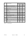
Section 4 – Recommended Spare & Replaceable Parts .......................................................... 36
Customer Service ................................................................................................................ 36
Ordering Parts ..................................................................................................................... 36
Power Converter Parts ........................................................................................................ 36
Flashhead Parts ................................................................................................................... 36
Photocell Parts .................................................................................................................... 36
Returning Equipment – Return Material Authorization (RMA)......................................... 41
Return to Stock Policy .................................................................................................... 42
FTB 312-4
Revision 4 – 1-8-2008
v
List of Figures
Figure 1-1 – TB1 Alarm Contacts ............................................................................................ 2
Figure 1-2 – 2903800 Board Configuration.............................................................................. 4
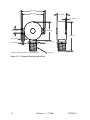
Figure 2-1 – Power Converter Mounting and Outline ............................................................ 12
Figure 2-2 – Flashhead Mounting and Outline ....................................................................... 13
Figure 2-3 – Photocell Mounting and Outline ........................................................................ 14
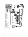
Figure 2-4 – Typical System Installation ................................................................................ 15
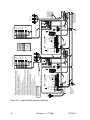
Figure 2-5 – Typical Multiple System Installation ................................................................. 16
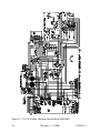
Figure 2-6 – PC 312-4 Power Converter Internal Wiring (110-120V) ................................... 17
Figure 2-7 – PC 312-4 Power Converter Internal Wiring (208-240V) ................................... 18
Figure 2-8 – Recommended Alarm Wiring ............................................................................ 19
Figure 2-9 – FH 306 Internal Wiring ...................................................................................... 20
Figure 2-10 – RS-485 Installation........................................................................................... 21
Figure 3-1 – Function Indicators............................................................................................. 29
Figure 3-2 – Unit Troubleshooting Guide .............................................................................. 33
Figure 3-3 – System Troubleshooting Guide .......................................................................... 35
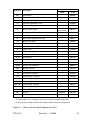
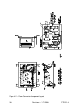
Figure 4-1 – Power Converter Major Replacement Parts ....................................................... 37
Figure 4-2 – Power Converter Component Layout................................................................. 38
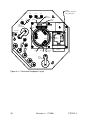
Figure 4-3 – Flashhead Major Replacement Parts .................................................................. 39
Figure 4-4 – Flashhead Component Layout............................................................................ 40
vi
Revision 4 – 1-7-2008
FTB 312-4
Section 1 – Introduction
and Operation
System
Performance Characteristics
The photocell senses changes in lighting
conditions from day to night and from
night to day thus signaling the power
converter to change its operation
appropriately. Also, a manual intensity
switch can override the photocell if
required.
Application - L-865 and L-864
Flash Intensity (nominal):
Day (White)
20,000 ± 25% ECD
Night (Red)
2,000 ± 25% ECD
White Backup
2,000 ± 25% ECD
Beam Spread
Horizontal: 360º
Vertical: 5º
Flash Rate
Day (White)
40 flashes per min.
Night (Red)
20 flashes per min.
White backup
40 flashes per min.
Electrical (PC 312-4)
AC Voltage
120 or 240V, 60 Hz
110 or 230V, 50 Hz
208-240V 50 Hz
Volt-Amperes
250 peak
Day (White)
130W
Night (Red)
250W
White Backup
75W
Specifications
Operation
Each single FTB 312-4 System consists of
a FH 306 Flashhead, a PC 312-4 Power
Converter, a PEC 510 Photocell, and a
connecting cable from the power converter
to the flashhead.
The power converter supplies the
controlling circuitry to convert main AC
power to the required voltages for internal
operation and the discharge energy for the
flashhead. It also controls the flash rate.
Physical
PC 312-4 (H x W x D, Weight)
14.00 x 16.75 x 8.44 in., 51 lbs.
355.6 x 425.5 x 214.4 mm, 23 kg.
FH 306 (H x Diameter, Weight)
17 x 18.25 in., 17 lbs.
431.8 x 463.5 mm, 7.7 kg.
PEC 510 Photocell (H x W x Depth)
3.06 x 2.58 x 1.02 in.
77.7 x 65.5 x 2.59 mm
Aerodynamic Wind Area
Flashhead
0.93 ft2, 0.0864 m2
Power Converter 1.63 ft2, 0.15 m2
Environmental
Complies with FAA specifications in
AC 150/5345-43.
FTB 312-4
The PC 312-4 Power Converter operates
an FH 306. It monitors flashhead operation
and signals an alarm if a failure occurs.
The flashhead begins to operate as soon as
power is applied. A photocell controls
intensity for the system.
In daylight, lights flash white at a rate of
40 flashes per minute (FPM) at an
intensity of 20,000 candelas. At night the
light flashes red at a rate of 20 FPM at an
intensity of 2,000 candelas.
Obstructions over 350 feet above ground
level require several interconnected PC
312-4 power converters (typically three)
operating the corresponding number of
flashheads. A master/slave control line
(two-wire) at terminals TB1-4 and TB1-5
at the front panel interconnects the units.
A sync pulse on the line flashes all the
lights in unison and at the same rate.
Revision 4 – 1-8-2008
1
Configurations
Models
Lights
Operation
312-4
312-4E
L-865 White (40 FPM)
L-864 Red (20 FPM)
L-810 Incandescent Markers
White During Daylight
Red During Night
312-4H
312-4EH
L-865 White (40 FPM)
L-864 Red (20 FPM)
L-810 Halogen / LED Markers
White During Daylight
Red During Night
The “E” option shown above denotes the addition of the optional modem card for remote
diagnostics and monitoring.
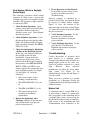
Alarm Contacts
INTENSITY SELECT
NIGHT MODE
16
COMMON
DAY MODE
15
NIGHT
INTENSITY
ERROR
DAY
RED
ALARM
18
17
14
12
11
COM
10
9
8
6
7
COM
WHT
5
4
3
BLK
WHT
2
1
BLK
PHOTOCELL
WHITE
ALARM
MASTER/SLAVE
INTERCONNECT
AUTO
PEC ERROR
CONTACTS SHOWN IN
NORMAL OPERATING STATE
(NO ALARMS OR ERRORS)
NIGHT
13
DAY
OUTPUT ALARM CONTACTS
TB1
Figure 1-1 – TB1 Alarm Contacts
2
Revision 4 – 1-7-2008
FTB 312-4
Contact
White Alarm
Red Alarm
Day Intensity Error
Night Intensity Error
Photocell Error
Day Mode
Night Mode
Indication
Combination of Day Intensity and Photocell Errors.
Combination of Night Intensity and Photocell Errors.
Incorrect day intensity.
Incorrect night intensity.
Photocell alarm. The PEC failed to transition within 19 hours.
Day mode operation.
Night mode operation.
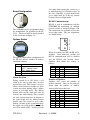
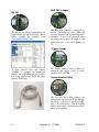
Photocell
The photocell changes resistance as ambient light changes from day to night or from night to
day. The Timing and Trigger Board (PCB1) in the master power converter then converts the
changes into the necessary circuit operation to flash the lights at the appropriate intensity for
day or night operation.
FTB 312-4
Revision 4 – 1-8-2008
3
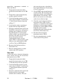
PCB1 Timing and Trigger Board
PCB1 controls and monitors the operation of the PC 312-4. Status indicators and setup
options are shown below.
Figure 1-2 – 2903800 Board Configuration
4
Revision 4 – 1-7-2008
FTB 312-4
slave units from causing the system to go
to white back up if a red failure occurs on
the slave. Generally, a system should only
go to white back up if the top (master
beacon) fails in red night mode.
Board Configuration
RS-485 Communication
The 2903800 board is programmed from
the manufacturer for operation in the PC
312-4. The board will be clearly marked
in the area shown in Figure 1-2.
RS-485 is used to communicate with the
FTM-5000 for monitoring of multiple
beacon systems as shown in Figure 2-10.
The connections are available on J8 in the
lower right corner. The pin assignments
are shown below:
Options Switch
The options switch allows configuration of
the RS-485 address, number of markers
and alarm isolation.
Switch
1
2-4
5-7
Function
Alarm Isolation
(OFF – (default) Isolate)
(ON – Report Alarm)
RS-485 Address
Number of Markers
2
OFF
ON
OFF
ON
OFF
Alarm Isolation
Setting switch #1 to ON allows a red
alarm to be sent to other units over the
master/slave sync. This feature is used to
allow a slave beacon to send the rest of the
system into white backup when a failure
occurs in red night mode. The Master
beacon will read the alarm and send all
beacons into white backup. This is useful
for stack systems that have all beacons at
the same height and any failing beacon
should cause the system to go to white
backup. All units in the system must have
the switch set to ON for this feature to be
used. The default (OFF – Isolate) prevents
FTB 312-4
When all switches are OFF, the RS-485 is
disabled. Once addressed, modem and
RS-232 communication will be disabled
and the RS-485 will become active.
Switches #2-4 define the address as
follows:
3
OFF
OFF
ON
ON
OFF
4
OFF
OFF
OFF
OFF
ON
Address
RS-485 Disabled
1
2
3
4
Number of Markers
Switches #5-7 select the number of
markers installed. Once set, the unit will
alarm when the number of markers
detected falls below this level.
5
OFF
ON
OFF
ON
OFF
ON
OFF
ON
6
OFF
OFF
ON
ON
OFF
OFF
ON
ON
Revision 4 – 1-8-2008
7
OFF
OFF
OFF
OFF
ON
ON
ON
ON
Markers
0
1
2
3
4
5
6
7
5
RES PEC Jumper
RS-232
The RS-232 port allows programming and
troubleshooting using Tech Eagle shown
below (available for download from
www.flashtechnology.com):
The RES PEC jumper is removed by
default. The FTB 312-4 uses a PEC 510
resistive photocell for determining mode
transition. To use an AC photocell, short
this jumper and connect the output of the
photocell to pins 4 (AC) and 5 (Return) of
J5.
Trigger Voltage
A direct connect cable, part number
3859001, is required for connection
between the 2903800 board and the PC.
For more information, select the Help
menu in Tech Eagle.
The trigger voltage neon provides an
indication that trigger power is being
supplied to the 2903800.
Communication LEDs
The TX and RX LED’s indicate the
transmission and reception of data through
the board’s serial port via the RS-232, RS485 or the modem card. The DCD LED
will be active when a connection has been
made via the modem.
6
Revision 4 – 1-7-2008
FTB 312-4
Internal Red Jumper
Status LEDs
The status LEDs display alarm and mode
information as follows:
LED
NITE ERR
DAY ERR
PEC ALM
WHT ALM
RED ALM
MKR ALM
FAN
SYNC
CONF
DAY
NITE
MKRS
Indication
Incorrect night intensity.
Incorrect day intensity.
Photocell alarm. The
PEC failed to transition
within 19 hours.
Combination of DAY ERR
and PEC alarm.
Combination of NITE
ERR and PEC alarm.
Detected markers have
fallen below the level set
by the options switch.
Not used.
The Master / Slave
Interconnect is active.
Flashes during normal
operation.
A valid flash has been
detected.
Day mode operation.
Night mode operation.
Marker output is active.
Always shorted for the FTB 312-4.
Optional Modem Card
The 2903801 modem board is installed in
the lower left corner of the board.
RS-485 Setup
RS485TERM and RS485PUP are open by
default and should be shorted only on the
last 2903800 board in the series of
equipment connected to an FTM-5000 as
shown in Figure 2-10.
FTB 312-4
The terminal block can be removed for
easy connection of the phone wires.
The modem is included with all “E”
(Eagle) systems or can be added later as an
upgrade to non “E” systems.
Revision 4 – 1-8-2008
7
Section 2 - Mounting, and
Installation
Unpacking
Inspect shipping cartons for signs of
damage before opening them. Check
package contents against the packing list
and inspect each item for visible damage.
Report damage claims promptly to the
freight handler.
secure the lens. The flashhead normally
contains no interlock. Disconnect primary
power to the power converter before you
open the flashhead. Wait one minute for
storage capacitors to drain down. Open the
flashhead and use a voltmeter to check that
no voltage potential exists between the red
and the blue wires on the ceramic terminal
posts.
Mounting
Tools
Power Converter
Although no special tools are necessary,
Flash Technology suggests the following
hand
tools
for
installation
and
maintenance:
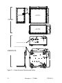
Mounting and outline dimensions for the
power converter are shown in Figure 2-1.
Flash Technology does not furnish
mounting hardware unless ordered as part
of an installation kit. Use the following
guidelines for mounting the power
converter:
•
9 or 12 inch, flat blade #2 screwdriver
•
#2 Phillips® head screwdriver
•
Medium slip joint pliers
•
Set of combination wrenches
•
Long-nose pliers
•
Assorted nut driver handles: 1/4”,
5/16”, 3/8” recommended
•
Analog volt-ohm meter
•
Multi-purpose crimp tool
Ensure that adequate space exists around
the equipment for access during
installation, maintenance and servicing.
Access
You must use a bonding strap on a bolt
through the power converter case leg.
Connect the strap to the site grounding
system.
Flashhead
WARNING
Before proceeding, read the warning on
Page iii. Disconnect the primary power
before opening enclosures.
Power Converter
The base of the power converter has
mounting feet. The cover lifts off for
unrestricted access to the interior. Release
the latches that secure the cover to remove
it for internal access.
Flashhead
Pivot the lens open by disengaging two
quick-release latches. Two lanyard cables
8
Allow space for air flow around the power
converter.
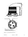
Mounting and outline dimensions for the
flashhead are shown in Figure 2-2. The
flashhead must be protected from lightning
strikes. The flashhead may be mounted to
painted or unpainted surfaces. One of the
mounting holes in the base of the
flashhead contains a built-in electrical
ground connection. Use the following
guidelines for mounting the flashhead:
Use a lightning rod extended above the
flashhead to protect it when it is mounted
at the uppermost part of the structure.
Avoid locating a lightning rod where it
would prevent tilting the lens open or
Revision 4 – 1-7-2008
FTB 312-4
interfere with access by maintenance or
service personnel.
You must use a bonding strap with a
flashhead mounting bolt when mounting
the flashhead to the structure, using the
mounting bolt to fasten the strap to the leg
that contains the ground connection.
Flashhead Leveling
The flashheads must be level for correct
vertical beam alignment. Two leveling
vials—aligned with the mounting feet—
are permanently attached to the flashhead
assembly. Typically, the mounting surface
for the flashhead is level and no
adjustments are required. When the
flashhead is level, bubbles in both leveling
vials are centered. For leveling, use the
following guidelines:
If adjustment is necessary, raise the
appropriate mounting foot with shims or
washers. Raising one foot by 1/16 inch
(1.6 mm) tilts the beam about 1/2 degree.
Take extreme care to ensure that all four
feet rest snugly against a firm mounting
surface before tightening the mounting
bolts. Failure to do so could result in
serious damage to the base when you
tighten the bolts.
Photocell
Mounting and outline dimensions for the
photocell are shown in Figure 2-3. The
photocell uses a male 1/2” NPT for
mounting. Use the following guidelines to
mount the photocell:
Locate the photocell where it has an
unobstructed view of the polar sky.
It must not view direct or reflected
artificial light.
The photocell may be supported directly
by electrical conduit.
Ensure that the installation is watertight.
FTB 312-4
Installation
This manual may not contain all the
information about installation wiring
required for your installation.
NOTE
If
installation
drawings
prepared
specifically for your site disagree with
information provided in this manual, the
site installation drawings should take
precedence. Consult any site-specific
installation wiring diagram supplied with
your equipment.
Flash Technology wiring diagrams
define only minimum requirements
recommended
for
satisfactory
equipment
operation.
It
is
the
responsibility of the installer to comply
with all applicable electrical codes.
You can find conduit and other
distribution wiring details on electrical
installation diagrams provided by Flash
Technology or others. Installation
instructions concerning red light marker
fixtures are not part of this manual.
All installation wiring should have an
insulation rating of 600 volts. You must
size power service wiring to satisfy the
load demand of the red light system (if
present) and the power converters. Read
the notes on the installation wiring
diagrams supplied both in this manual and
with the equipment. See Figure 2-9 for
information
about
wiring
alarm
connections to the main panel of the power
converter.
Power Converter Wiring
Consult the installation wiring drawings.
For service wiring, consider the voltage,
length of the wire run, and the total load
(number of lights). Assume a load of 175
volt-amperes per light, and do not permit
the line voltage to drop by more than 5%
due to wire resistance. Assume a load of
175 volt-amperes per light to determine
the slow-acting fuse ratings at the power
distribution panel. Use a value of 250 volt-
Revision 4 – 1-8-2008
9
amperes per light to determine fast-acting
fuse ratings at the power distribution panel
and to select a system feeder transformer
(if used).
In multiple-unit systems, the master unit
and slave units communicate over the
“master/slave” interconnect wiring. Twist
the wires together at the rate of 12 twists
per foot. The recommended minimum size
for control and signal conductors is #14
AWG.
Flashhead Wiring
The power converter and flashhead are
interconnected by the flashhead cable.
When Flash Technology Part Number
6340, or equivalent cable, is used, the two
may be separated by a distance up to 600
feet. Consult the factory when a greater
separation is necessary. The cable between
the power converter and flashhead requires
five conductors with 600 volts (minimum)
insulation. Two of the conductors must be
#10 AWG. The other three may be #16
AWG (minimum; for mechanical strength)
if you are cabling together individual
wires.
To ensure long-term equipment reliability,
use continuous wiring between the power
converters and their flashheads without
intervening junctions or splices.
Securing the Cable
Flash Technology recommends the
following method for securing the
flashhead cable to a skeletal structure:
1. Run the cable along one of the tower
legs and wrap two full turns of twoinch Scotchrap™ #50 tape, or the
equivalent, around the cable and tower
leg at regular intervals of about 5 feet
(1.5 meters).
2. Wrap three full turns of one-inch
Scotchrap Filament #890 tape, or the
10
equivalent, over the Scotchrap #50
tape.
3. Wrap four full turns of two-inch
Scotchrap #50 tape, or the equivalent,
over the Scotchrap Filament #890 tape.
4. Perform steps 1 through 4 also directly
above and below any tower leg flanges
that the cable may cross.
Photocell Wiring
The photocell is supplied with pigtails for
connection to wires that connect to the
power converter. It is connected to the
main panel of the power converter. It may
be located any practical distance from the
power converter. The recommended
minimum wire gauge is #16 AWG.
The photocell terminals on the slave
power converters must be connected from
TB1-1 to TB1-2. (An alternative jumper
may be installed on PCB1 J18-1 to J18-2.)
Also, you connect the master unit (to
which the photocell is directly connected)
to the top flashhead.
Installation Checklist
Complete the following steps before
applying power to the lights.
1. Inspect all equipment for damage.
2. Verify the received equipment against
the packing list to ensure
completeness.
3. Power Converter Mounting. Position
and mount each unit correctly,
allowing adequate clearance for
opening the covers. Use the following
checks:
1. Ensure that the case is mounted
upright, is water tight, and
grounded to the site grounding
system.
2. Check hardware to ensure that all
mounting hardware is tight.
Revision 4 – 1-7-2008
FTB 312-4
3. Ensure that only the bottom of the
case has drain holes and that they
are clear.
4. Ensure that no holes are punched
or drilled on the top surface of the
case.
5. Ensure that air can flow around the
case.
6. Mount the power converter away
from radio frequency interference
(RFI).
4. Power Converter Wiring. Examine the
installation drawings and use the
following checks:
1. Check for proper incoming service
voltage.
2. Wire each unit according to the
instructions.
3. In multiple installations of three
systems, all three power converters
should be on the same breaker.
4. Check all electrical connections for
tightness.
5. Check all terminal strip
connections for tightness.
6. Ground the power converter.
7. Wires at master/slave interconnect
terminals should be daisy-chained
as a twisted pair between the
master power converter and the
slave units. The rate of twist is 12
per foot. If a shielded cable is used,
ground the shield. For example,
ensure that TB1-4 is connected to
all TB1-4 connections on all units,
and TB1-5 is similarly connected.
5. Alarm Wiring.
1. If external alarm detection circuit
responds to closed contacts, ensure
that they are wired to the contacts
on TB1 that close on alarm.
2. If external alarm detection circuit
responds to open contacts, ensure
FTB 312-4
that they are wired to the contacts
on TB1 that open on alarm.
3. Alarm wiring should be lightning
and RFI protected: shielded,
grounded shield, and in a conduit.
4. If a specific alarm is ganged
together from all power converters
as one, ensure that the wiring
follows local installation
instructions.
6. Flashhead Mounting.
1. Ensure that the flashhead lens can
be opened without striking other
objects.
2. Level and aim the flashhead.
7. Flashhead Wiring.
1. Protect the top flashhead against
lightning strikes.
2. Ground the flashhead.
3. Check the wiring of the flashhead
cable to the flashhead.
4. Secure the flashhead cable to the
tower. Support and tape the
flashhead cable to prevent its
movement by the wind.
8. Photocell.
1. Locate photocell where it views
unobstructed polar sky with no
direct or reflected artificial lighting
striking it.
2. Mount the photocell vertically to
prevent water from entering the
unit. Ensure watertight
connections.
3. Connect the photocell to the master
power converter.
After completing all the steps listed above,
turn on the power and perform an
operational checkout from procedures in
Section 3 of this manual.
Revision 4 – 1-8-2008
11
(425.5)
5.00
(127)
LEFT SIDE VIEW
AS WALL MOUNTED
FRONT VIEW
AS WALL MOUNTED
(356)
COVER
(214)
BOTTOM VIEW
AS WALL MOUNTED
1.06
(27)
.875
(22.2)
.875
(22.2)
BOTTOM VIEW AS WALL MOUNTED
1.06
(27)
(170)
.344
(8.74)
.875
(22.2)
REAR OF CHASSIS AS WALL MOUNTED
(311)
(54.9)
Ø .44 INCH
(11.2)
BASEPLATE
(127)
15.2
(386)
Ø.44 INCH
(11.2)
Figure 2-1 – Power Converter Mounting and Outline
12
Revision 4 – 1-7-2008
FTB 312-4
23.8
(603)
CLEARANCE
REQUIRED
17
(430)
18.3
(463)
.625 (15.9) DIA. MOUNTING HOLE
(4 PLACES EQUALLY SPACED)
Ø13.25 BOLT HOLE CIRCLE
NOTES:
1. WEIGHT: 17 LBS (7.7 KG)
2
2
2. AERODYNAMIC WIND AREA: .93 FT (.0864 M )
3. DIMENSIONS ARE IN INCHES (MILLIMETERS)
4. ACCESS TO THE FLASHHEAD MUST REMAIN UNOBSTRUCTED
5. FLASHHEAD SHOULD HAVE LIGHTNING PROTECTION
Figure 2-2 – Flashhead Mounting and Outline
FTB 312-4
Revision 4 – 1-8-2008
13
2.58 (65.5)
2.28 (57.8)
1.02 (25.9 )
0.10 (2.54)
0.375 (9.53)
1.92 (48.8)
3.06 (77.7)
0.33 (8.38)
HEX 1.0 (25.4)
0.125 (3.18)
NOTE: ALL DIMENSIONS ARE IN INCHES (MILLIMETERS)
1/2" NPT
Figure 2-3 – Photocell Mounting and Outline
14
Revision 4 – 1-7-2008
FTB 312-4
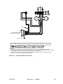
Figure 2-4 – Typical System Installation
Revision 4 – 1-8-2008
ALARM
(NOTE 6)
NOTE 12
GND
PRIMARY NEUT
POWER LINE 2
LINE 1
NOTE 1 & 5
NOTES
3&4
TB1 1 2 3 4 5 6 7 8 9 10 11 12 13 14 15 16 17 18
TWO CONDUCTORS
(#16 AWG MINIMUM)
PHOTOCELL
WHT
PHOTOCELL
BLK
AUTO
ALARM
INTENSITY
SELECT
COM RED
OUTPUT ALARM CONTACTS
CONTACTS SHOWN IN NORMAL
OPERATING STATE
(NO ALARMS OR ERRORS)
NIGHT ERROR
NIGHT
PEC ERROR
DAY MODE
DAY
BLK
MASTER/SLAVE
INTERCONNECT
WHT
INTENSITY
DAY
MOUNT THE PHOTOCELL
TO FACE THE POLAR SKY
AND MOUNT IT
VERTICALLY AT THE TOP
END OF A VERTICAL
LENGTH OF CONDUIT TO
PREVENT WATER FROM
ENTERING THE UNIT.
COM WHITE
PC 312-4 POWER CONVERTER
HV
SHIELD
INPUT
POWER
F1
TRIGGER
TRIG RTN
CATHODE
ANODE
SUPPLY LIGHTNING
FLASHHEAD
CABLE CHART
TOP FLASHHEAD
PROTECTION FOR THE
#10 AWG
#10 AWG
#16 AWG
#16 AWG
#16 AWG
NOTE 5
GND
GND
NEUT
DENOTES WIRE SPLICE CONNECTIONS
NOTE 2
NOTES
3&4
1 2 3 4 5 6
MRKS
F4
F5
MIN. INSULATION 600V
COLORS FOR REF. ONLY
RED
BLU
BLK
WHT
PUR
MINIMUM REQUIREMENTS
FOR USER'S CABLE
NOTE 8
TB4 1 2 3
GND
PUR
WHT
BLK
BLU
1
2
3
4
5
6
TB2
RED
WARNING
L1
7. JUNCTION BOX FOR DISTRIBUTION WIRING TO MARKERS
TYPICALLY FURNISHED BY OTHERS AND LOCATED AS CLOSE AS
POSSIBLE TO THE POWER CONVERTER.
NIGHT MODE
NOTE 11
12. BOND CASE TO THE SITE GROUNDING SYSTEM.
5. USE LINE 1 AND NEUT FOR 120V, 60 Hz;
USE LINE 1, LINE 2 AND NEUT FOR 240/120V, 60 Hz.
N
6. UNIT IS FACTORY WIRED FOR NAMEPLATE VOLTAGE.
10. THE MARKER FIXTURES MAY BE SUPPLIED BY OTHERS.
11. MOUNT THE POWER CONVERTER VERTICALLY.
4. USER'S ALARM CIRCUITS NOT SHOWN.
9. THE TOTAL LINE DROP, INCLUDING INPUT SERVICE WIRING
AND BRANCH LINES TO THE L-810 MARKER LIGHT SOCKETS,
MUST NOT EXCEED 3% OF RATED VOLTAGE.
2. USE A CONTINUOUS CABLE FROM THE POWER CONVERTER
TO THE FLASHHEAD WITHOUT JUNCTIONS OR SPLICES.
COMMON
TEMP SENSE
3. CONTACT RATING 1 AMPERE, 120 VAC. EXTENDED MONITORING IS
AVAILABLE ON FTB 312-3AE SYSTEMS ONLY ("A" MODELS).
8. FTCA RECOMMENDS #12 AWG AS THE MAXIMUM CONDUCTOR
SIZE FROM TB5 TO THE JUNCTION BOX. USE LARGER
CONDUCTORS FOR THE BRANCH FROM THE JUNCTION BOX
TO THE MARKER FIXTURES, IF REQUIRED. SEE NOTE 9 TO
DETERMINE THE BRANCH CONDUCTOR SIZE.
NOTES:
1. THE AC INPUT POWER CONDUCTOR SIZE DEPENDS ON THE SERVICE
VOLTAGE, THE DISTANCE FROM THE SOURCE, THE NUMBER OF
POWER CONVERTERS, AND THE NUMBER OF L-810 MARKER LIGHTS
SERVED. USE 250 VA PER POWER CONVERTER PLUS 116 VA PER
L-810 MARKER LIGHT. ALSO SEE NOTE 9.
L2
FTB 312-4
15
PUR
WHT
BLK
BLU
RED
NOTE 7
NOTE 9
NOTE 10
TYPICAL MARKER
TIER L-810'S
FTCA PN 6340 OR USER'S CABLE
(SEE CABLE CHART)
GND
SHIELD
PUR
WHT
BLK
BLU
RED
FH 306 FLASHHEAD
Figure 2-5 – Typical Multiple System Installation
COM RED
ALARM
COM WHITE
ALARM
PRIMARY POWER
FROM A SINGLE
20A BREAKER
(NOTE 6)
TWO (2) #16 AWG 600V MIN
CONDUCTORS TWISTED TOGETHER
NOTE 1 & 5
GND
LINE 1
NEUT
LINE 2
NOTE 11
NOTE 13
NOTES
3&4
1 2 3 4 5 6 7 8 9 10 11 12 13 14 15 16 17 18
TWO CONDUCTORS
(#16 AWG MINIMUM)
TB1
NIGHT
INTENSITY
SELECT
BLK
PHOTOCELL
WHT
INTENSITY
ERROR
DAY
NIGHT
AUTO
PHOTOCELL ERROR
DAY MODE
DAY
BLK
MASTER/SLAVE
INTERCONNECT
WHT
PHOTOCELL
CONTACTS CLOSE DURING DAY
OUTPUT ALARM CONTACTS
CONTACTS SHOWN IN NORMAL
OPERATING STATE
(NO ALARMS OR ERRORS)
COMMON
PC 312-4 POWER CONVERTER (MASTER)
INPUT
POWER
NEUT
NOTE 5
NOTE 1 & 5
NOTES
3&4
1 2 3 4 5 6
GND
GND
MRKS
F4
F5
PUR
#16 AWG
WHT #16 AWG
PUR #16 AWG
BLK
RED #10 AWG
BLU #10 AWG
MIN. INSULATION 600V
COLORS FOR REF. ONLY
OUTPUT ALARM CONTACTS
CONTACTS SHOWN IN NORMAL
OPERATING STATE
(NO ALARMS OR ERRORS)
NOTE 7
NOTE 13
NOTE 11
NOTES
3&4
GND
SHIELD
PUR
WHT
BLK
BLU
RED
PUR
WHT
BLK
BLU
RED
HV
F1
INPUT
POWER
NOTES 1 & 5
NEUT
DENOTES WIRE
SPLICE CONNECTIONS
NOTE 7
NOTE 9
MASTER/SLAVE INTERCONNECT
LINE TO ADDITIONAL SLAVE UNIT
(TYPICALLY, ONE MASTER AND
TWO SLAVES ARE CONNECTED
TOGETHER AT TB1-4 AND TB1-5.)
LAST SLAVE UNIT (NOT SHOWN HAS
SIMILAR POWER AND FLASHHEAD WIRING
NOTE 2
NOTE 5
NOTES
3&4
TO
LAST
SLAVE
UNIT
LAST SLAVE UNIT
(NOT SHOWN) DOES
NOT HAVE MARKERS.
MARKERS ARE
CONNECTED TO THE
MASTER UNIT AND
FIRST SLAVE UNIT.
NOTE 10
TYPICAL MARKER
TIER L-810'S
1 2 3 4 5 6
GND
GND
MRKS
F4
NOTE 8
TB4 1 2 3
GND
1 ANODE
2
3 CATHODE
4 TRIGGER
5 TRIG RTN
6
TB2
SHIELD
PUR
WHT
BLK
BLU
RED
WARNING
F5
FTCA PN 6340 OR USER'S CABLE
(SEE CABLE CHART)
1 2 3 4 5 6 7 8 9 10 11 12 13 14 15 16 17 18
NOTE 12
TB1
NIGHT
INTENSITY
SELECT
AUTO
DAY
DENOTES WIRE
SPLICE CONNECTIONS
NOTE 9
FLASHHEAD
CABLE CHART
MINIMUM REQUIREMENTS
FOR USER'S CABLE
PC 312-4 POWER CONVERTER (SLAVE)
NOTE 10
TYPICAL MARKER TIER L-810'S
GND
SHIELD
PUR
NOTE 8
NOTE 2
TB4 1 2 3
SHIELD
BLU
1 ANODE
2
3 CATHODE
BLK
4 TRIGGER
WHT
5 TRIG RTN
PUR
6
F1
GND
RED
TB2
WARNING
HV
FTCA PN 6340 OR USER'S CABLE
(SEE CABLE CHART)
CONTACTS CLOSE AT NIGHT
WHT
BLK
PHOTOCELL
WHT
BLK
ALARM
WHT
COM WHITE
BLU
ALARM
BLK
COM RED
BLU
BLK
MASTER/SLAVE
INTERCONNECT
WHT
INTENSITY
ERROR
DAY
NIGHT
MOUNT THE PHOTOCELL VERTICALLY AT
THE TOP END OF A VERTICAL LENGTH
OF CONDUIT TO PREVENT WATER FROM
ENTERING THE UNIT. FACE IT TOWARD
THE POLAR SKY.
NIGHT MODE
SUPPLY LIGHTNING
PROTECTION FOR THE
TOP FLASHHEAD
PHOTOCELL ERROR
DAY MODE
RED
COMMON
RED
CONTACTS CLOSE DURING DAY
1. AC INPUT POWER CONDUCTOR SIZE DEPENDS ON THE SERVICE VOLTAGE,
THE DISTANCE FROM THE SOURCE, THE NUMBER OF POWER CONVERTERS
AND NUMBER OF L-810 MARKER LIGHTS SERVED. USE 250 VA PER POWER
CONVERTER PLUS 116 VA FOR EACH L-810 MARKER LIGHT. ALSO SEE NOTE 9.
2. USE A CONTINUOUS CABLE FROM THE POWER CONVERTER
TO THE FLASHHEAD WITHOUT JUNCTIONS OR SPLICES.
3. CONTACT RATING 1 AMPERE, 120 VAC. EXTENDED MONITORING IS
AVAILABLE ON THE 312-3 "A" MODELS ONLY.
4. USER'S ALARM CIRCUIT NOT SHOWN.
5. USE LINE 1 AND NEUT FOR 120V, 60 Hz;
USE LINE 1, LINE 2 AND NEUT FOR 240V, 60Hz.
6. UNIT IS FACTORY WIRED FOR NAMEPLATE VOLTAGE.
7. OTHERS TYPICALLY FURNISH THE JUNCTION BOX FOR DISTRIBUTION WIRING
TO THE MARKERS. LOCATE THE JUNCTION BOX AS CLOSE AS POSSIBLE TO
TO THE POWER CONVERTER.
8. FTCA RECOMMENDS USING #12 AWG AS THE MAXIMUM CONDUCTOR SIZE
FROM TB5 TO THE JUNCTION BOX. USE LARGER CONDUCTORS FOR THE
BRANCH FROM THE JUNCTION BOX TO THE MARKER FIXTURES, IF REQUIRED.
SEE NOTE 9 TO DETERMINE THE BRANCH CONDUCTOR SIZE.
9. THE TOTAL LINE DROP, INCLUDING THE INPUT SERVICE WIRING
AND BRANCH LINES TO THE L-810 MARKER LIGHT SOCKETS, MUST
NOT EXCEED 3% OF THE RATED VOLTAGE.
10. MARKER FIXTURES MAY BE SUPPLIED BY OTHERS.
11. MOUNT THE POWER CONVERTER VERTICALLY.
12. TERMINALS AT TB1-1&2 MUST BE JUMPERED ON SLAVE UNITS.
13. BOND CASE TO SITE GROUNDING SYSTEM.
L1
N
L2
FH 306 FLASHHEAD
NIGHT MODE
FH 306 FLASHHEAD
CONTACTS CLOSE AT NIGHT
NOTES:
L1
Revision 4 – 1-7-2008
N
L2
16
FTB 312-4
Figure 2-6 – PC 312-4 Power Converter Internal Wiring (110-120V)
FTB 312-4
Revision 4 – 1-8-2008
17
Figure 2-7 – PC 312-4 Power Converter Internal Wiring (208-240V)
18
Revision 4 – 1-7-2008
FTB 312-4
ALARM
130VAC
MOV
130VAC
MOV
GND
SHIELD
CUSTOMER CONNECTION
TO ALARM RELAY CONTACTS
METALLIC CONDUIT
FLASH TECHNOLOGY ALARM RELAY CONTACTS ARE PROTECTED FROM VOLTAGE TRANSIENTS OF UP TO 1000 VOLTS.
HOWEVER, WIRED ALARM CONTACTS CAN BE SUBJECTED TO VOLTAGES GREATER THAN 1000 VOLTS BECAUSE OF
LIGHTNING. THE FOLLOWING RECOMMENDATIONS MINIMIZE THE POSSIBILITY OF DAMAGE CAUSED BY HIGH VOLTAGE
NOTES:
1.
2.
3.
4.
USE SHIELDED CABLE TO ATTACH FLASH TECHNOLOGY ALARM RELAY CONTACTS TO EXTERNAL EQUIPMENT.
ATTACH THE SHIELD WIRE TO A GND (GROUND) TERMINAL ON THE FLASH TECHNOLOGY POWER CONVERTER AS SHOWN.
WHEN POSSIBLE, ROUTE ALARM CONTACT WIRING IN METALLIC, GROUNDED CONDUIT.
FOR ADDITIONAL PROTECTION, ADD MOVs (VARISTORS) FROM EACH ALARM RELAY CONTACT TERMINAL TO A GND
TERMINAL AT THE FLASH TECHNOLOGY POWER CONVERTER.
Figure 2-8 – Recommended Alarm Wiring
FTB 312-4
Revision 4 – 1-8-2008
19
RED 14
SHLD
ANODE
T101
TRIGGER
TRANSFORMER
TRIGGER
FT101
WHT
P1
BLU
RED
BLU 14
P2
CATHODE
RC101
P7
T102
COUPLING
TRANSFORMER
BLU
RC102
P3
P6
BLK
BLK
P4
N.C.
WHT
WHT
BR101
P5
PUR
PUR
L101
BLU
C NC
NO
SW101
FILTER
DOWN
SWITCH
BR102
BLU
BLK
WHT/RED
WHT
SW102
MOTOR
STOP
SWITCH
BLU
BLK
C NC
NO
BLU
RED
BLU
WHT/ORN
WHT
B101
MOTOR
MP101
CLUTCH
BLU
P14
P15
P16
C101
P13
BLU
BLU
C102
BLU
BLU
Figure 2-9 – FH 306 Internal Wiring
20
Revision 4 – 1-7-2008
FTB 312-4
Figure 2-10 – RS-485 Installation
FTB 312-4
Revision 4 – 1-8-2008
21
Section 3 - Maintenance
and Troubleshooting
Safety
WARNING
STOP: Before proceeding read the
warning on Page iii.
Work safely, as follows:
1. Remove rings and watches before
opening the equipment.
it gently with a soft cloth or paper
towel.
7. Clean the inside surface of the lens
with an Flash Technology-approved
professional plastic cleaner. Wipe the
lens with cheesecloth only. Do not use
regular cloth or paper towels. A lens
cleaning kit, Part Number 8630801, is
available from Flash Technology.
Contact Customer Service at 1-800821-5825.
2. Shut off the equipment.
Storage
3. Remove the component or connect the
test instruments.
Store equipment indoors when not in use.
Circuit board, when not installed in the
equipment, should be kept in antistatic
bags or containers.
4. Replace the component.
5. Turn on the power and test the system.
6. Turn off the power and disconnect the
test equipment.
Preventive Maintenance
Carry out the following inspection and
cleaning procedures at least once a year:
1. Verify that moisture has not
accidentally entered the equipment
through gaskets or seals, or collected
inside as condensation.
2. Verify that all drain holes are clear.
3. Check terminal blocks and relays for
corrosion or arcing. Clean or replace
any component that shows evidence of
high-voltage damage.
4. Check flashtube connections for signs
of pitting or arcing. Verify that anode
and cathode connections are firmly
tightened.
5. Check all electrical connections for
tightness and verify the absence of
corrosion or electrical arcing.
6. Clean the outside surface of the lens
with liquid detergent and water. Wipe
22
Diagnostic Testing
The only effective way to check out
interconnected lights is to disconnect the
master/slave interconnect wire that is
connected between power converters and
check the power converters as single units,
as described in Master Unit.
Sync Signal Evaluation
Refer to Figure 2-6. Note that, for each
power
converter,
the master/slave
interconnect line and its return line are
connected to TB1-4 and TB1-5
respectively. All units place a pulse on the
line, which causes the power converters to
flash all the lights at the same time. This
pulse is the synchronization pulse. PCB1
in each power converter generates a sync
pulse. The first sync pulse to be placed on
the line synchronizes the remaining lights.
The width of the sync pulse controls the
mode of operation.
In the event of a top-most red light failure
at night, the power converter places a
back-up signal on the line that causes all
connected units to flash the white lights at
the correct night intensity.
Revision 4 – 1-7-2008
FTB 312-4
The sync signal is a pulse and difficult to
evaluate with a meter. You can detect the
sync pulse as an instantaneous movement
of the meter indicator. A digital meter with
a max-min function may capture part of
the pulse. This is generally a sufficient
indication of a pulse being present. (A
24V pulse of 16 ms. width might read 12V
on a 100 ms. capture time of max-min
function.)
RFI Problems
The presence of radio frequency
interference (RFI) can burn out
components; cause a light to flash
intermittently, at the wrong rate, or at the
wrong intensity. RFI can enter the light by
any wire to or from the unit. The circuits
reject or bypass RFI, but Flash
Technology cannot guarantee complete
immunity beforehand. After installation,
you may find it necessary to add external
filters or use other methods to reduce RFI
entering the equipment. To minimize
interference, ensure proper installation in
accordance with AC 70-7460, Appendix 1,
Figure 2.
Component Testing
The following procedures describe how to
check most of the unit's major electrical
components. Always make resistance
measurements with the primary power
turned off. However, you must make
voltage measurements with power applied.
Thus, for your safety, carry out all
preliminary steps such as connecting test
leads or circuit jumpers, or disconnecting
existing circuit connections with the power
off.
Capacitors
Evaluate the condition of a capacitor with
an analog volt-ohmmeter operating in the
resistance mode. The following method
assumes an instrument with a X100
resistance scale.
FTB 312-4
Place the meter leads across the terminals
of an isolated (no electrical connections to
other circuits) and fully discharged
capacitor. Observe the subsequent needle
movement.
If the capacitor is functional, the needle
initially indicates zero ohms, but soon
begins to rise to higher indicated values. A
capacitor that is disconnected from other
circuitry is defective if it does not exhibit
this behavior. The length of time it takes
the needle to reach the 1-megohm reading
(about 65% full-scale) is a measure of the
capacitance. For example, the time is
about 5 seconds for a 10-mfd. capacitor, or
10 seconds for a 20-mfd. capacitor, and so
forth.
Manually discharge the capacitor before
repeating this measurement. This test may
not detect a malfunction that occurs only
at high voltage.
A bank of capacitors connected in parallel
may be checked as a single unit. If the test
indicates a short circuit, the individual
capacitors have to be disconnected and
checked separately. A shorted capacitor is
indicated if the resistance does not rise
above zero after several seconds of
measurement.
Wiring and Cabling
Wires or cables that move repeatedly will
ultimately break. Ensure that all cables
(the flashhead cable in particular) are
securely fastened at short intervals to the
structure or other supports.
Inspection
Closely inspect the units and check the
connections against the installation
instructions. Also, a close inspection may
reveal
insulation
breakdown,
an
overheated component, corrosion, loose
connections, faulty relays, incorrect
hookup, and so forth.
Revision 4 – 1-8-2008
23
Power Transformer (T1)
Power Converter
Burst Choke (L1)
Measure the resistance of L1 from TB3-5
to ceramic post E4 (at burst resistor R2).
Its resistance should be approximately 7
ohms.
Relays (K2, K3)
A malfunctioning relay may have faulty
contacts, a sticky mechanism, or a
defective coil. You may determine the first
two possibilities by inspection and
manually exercising the armature. You can
confirm a defective coil by measuring the
resistance. To measure the resistance of
relay coils, first remove the wires from
one of the connections to the coil terminals
on the relay.
The resistance across the coil of the K2
Mode Relay or the K3 Discharge Relay
should measure approximately 290 ohms.
Timing and Trigger Board (PCB1)
Replace this circuit board with one known
to be in good condition.
HV Rectifier Board (PCB2)
Replace this circuit board with one known
to be in good condition.
Sense Board (PCB4)
Replace this circuit board with one known
to be in good condition.
To test this transformer, first remove the
PCB1 and the HV rectifier board (PCB2).
Apply power to the unit and measure
secondary winding voltages at the
terminals indicated below:
Terminals
Voltage Range
Allowed
TB3-1 to TB3-9
900-1050 VAC
Terminal 2 of
Relay K2 or K3 to
chassis
100-120 VAC
J3-1 to J3-2 on
PCB1
22-26 VAC
If the voltage on TB3-1 to TB3-9 is
substantially below the specified minimum
value, check the C4 Tuning Capacitor.
Flashhead
Flashtube (FT101)
Visually inspect the flashtube for broken
electrodes, cracked glass, and the solder
connections of the pins. A darkened
envelope does not necessarily mean the
light output would be unacceptable.
Before concluding that a faulty flashtube
is responsible for an inadequate flash, first
rule out other possible causes such as
weak or absent discharge voltage or
triggering pulses.
Trigger Transformer (T101)
Discharge Resistor (R1)
The resistance of R1 between ceramic
posts E1 and E2 should be 35,000 ohms.
Burst Resistor (R2)
The measured resistance of the secondary
winding (potted assembly) should be
approximately 150 ohms. Check the ferrite
core for cracks. Check the mounting
screws for tightness.
The resistance of R2 between posts E3 and
E4 should be 500 ohms.
24
Revision 4 – 1-7-2008
FTB 312-4
Trigger Coupling Transformer
(T102)
The coupling transformer should not have
open windings. An ohmmeter will indicate
a shorted winding because of the wire size.
Check with an ohmmeter at the wire
terminals.
The general procedure for removing
components follows:
1. Obtain access to the component in
question.
Photocell Testing
Use the following procedure:
•
1. First, disconnect the photocell. The
system should go to night operation
after approximately one minute.
2. If multiple beacon system, disconnect
the master/slave interconnect line on
each power converter.
3. Operate the manual intensity control
switch on each power converter in
turn.
4. If each power converter operates
correctly with the manual intensity
control switch, troubleshoot the
photocell wiring or the circuits in the
erroneously operating power
converter.
5. Reconnect all wires.
During daylight, completely block light
from entering the photocell. If the system
does not enter night mode after a few
minutes, replace the photocell. At night,
shine a light on the photocell, if the system
does not enter day mode after a few
minutes, replace the photocell.
Component Removal and
Replacement
A power converter component location
diagram is provided in Figure 4-1. A
flashhead component location diagram is
provided in Figure 4-3. A flashhead
electrical wiring diagram is provided in
Figure 2-10. A power converter internal
wiring diagram is provided in Figure 2-7.
FTB 312-4
Note the location and color of all wires
that you disconnect. When you replace the
wiring after you replace the components,
ensure that the wiring agrees with Figure
2-7.
Disconnect completely or partially
the wiring to components first that
prevent clear access.
2. Completely remove or relocate these
components.
3. Disconnect the wiring to the
component that you want to replace.
4. Remove this component.
5. Replace everything in the reverse
order: first the component, then the
wiring. In some cases, you may have
to place some wires on the component
before you fasten it in place, then
replace the remaining wires.
Most components are relatively easy to
access for removal. Only those that are
more difficult are described.
Power Converter Components
Capacitors
Before removing or replacing a capacitor
always ensure it is discharged by checking
with a voltmeter directly across the
terminals. Discharge a capacitor by
placing a resistance (25 watts/10,000 ohms
or greater) between its terminals. Direct
shorting may damage the capacitor, and
connecting the terminals to the equipment
chassis may fail to discharge it.
Remove the fuse for this procedure to
prevent application of power if the
interlock switch is accidentally pressed.
Revision 4 – 1-8-2008
25
Removal
Input Power Module
1. Disconnect the wires leading to
capacitors.
Removal
2. Remove the hold-down screws.
3. Lift the capacitors from their receiving
holes.
Replacement
1. Reverse the removal procedure.
2. Verify that wiring is in accordance
with the wiring diagram in Figure 2-7.
Wires must be replaced exactly as
removed. In some instances, a quickconnect wire terminal does not seat
properly if it is not placed on the
terminal cluster exactly as it was
before removal. This occurs by
interference between the insulation on
the wire terminal and the insulation
surrounding their terminal cluster on
the capacitor. Flash Technology
recommends that you lightly squeeze
the quick-connect wire terminals with
pliers before reinstalling them over the
capacitor terminal blades.
Timing and Trigger Board Assembly
(PCB1)
PCB1 is mounted on the left side of the
component bracket.
Removal
1. Remove all green connector plugs
from PCB1 headers.
2. Loosen (but do not remove) the four
screws located near the corners of the
board.
3. Lift the board from the bracket.
1. Remove all accessible wires and cable
connectors attached to the module and
to T1 located under the module.
2. Loosen the truss-head screws in the
base that fasten the module to the base.
3. Remove the screw under the ground
terminal to the left of TB4. This screw
fastens the module to the component
bracket.
4. Carefully slide the module to the right
and lift it out. Ensure that connectors
are not bent while doing so.
5. Remove any additional connections
necessary to remove the module.
Replacement
1. Reverse the removal procedure.
2. Verify that wiring agrees with Figure
2-7 and restore the wire routing to its
original state.
Power Transformer (T1)
Removal
1. Remove the Input Power Module.
2. Remove the four screws holding the
transformer to the base plate and
remove the transformer.
Replacement
1. Reverse the removal procedure.
2. Verify that wiring agrees with Figure
2-7 and restore the wire routing to its
original position.
Component Bracket
Replacement
1. Cut the appropriate program jumpers
according the board just removed.
The Component Bracket supports the
capacitors, terminal blocks, PCB1, PCB2,
and other components.
2. Reverse the removal procedure.
26
Revision 4 – 1-7-2008
FTB 312-4
Removal
1. Loosen the four screws holding PCB1
to the bracket and lift PCB1 up and
out.
Mode Relay (K2), Discharge Relay
(K3)
Remove the Component Bracket for
adequate access to Relay K2.
2. Loosen the two truss-head screws
below PCB1 on the left side of the
bracket that hold the bracket to the
base plate.
Removal
3. Remove the screw on the left front side
of the bracket that fastens the bracket
to the Input Power Module.
3. Remove the Component Bracket.
4. Loosen the two truss-head screws in
the base plate on the right side of the
bracket that hold the bracket to the
base plate.
5. Carefully disconnect the wires from
the terminals of the component and
note their locations so that you may
more easily replace them.
5. Slide the bracket up off the screws. Be
careful of the cable and cable
connectors. You may hang the bracket
over the edge of the connector panel to
perform the remaining steps.
6. Remove the screws that hold the
component to the base plate.
1. Remove the capacitors.
2. Remove PCB1.
4. Loosen the screws that fasten the
wiring connectors to the relay.
7. Remove the component
Replacement
Replacement
1. Reverse the removal procedure.
1. Reverse the removal procedure.
HV Rectifier Board (PCB2)
2. Verify that wiring agrees with Figure
2-7 and restore the wire routing to its
original state.
The HV rectifier board is mounted on the
right of the Component Bracket.
Flashhead Components
Removal
Flashtube (FT101)
1. Remove the Component Bracket to
gain access to PCB2.
Use the following
replacement procedures:
2. Loosen, but do not remove, the screws
holding PCB2 to the terminal block
TB3.
Removal
3. Slide the circuit board out from under
the terminal block screws.
removal
and
1. Using a #2 flat-blade screwdriver,
loosen the three screws (on screw
lugs)—this enables you to disengage
the flashtube.
2. Carefully lift the flashtube upward
from the assembly.
Replacement
1. Reverse the removal procedure.
2. Restore the wire routing to its original
state.
FTB 312-4
Revision 4 – 1-8-2008
27
Replacement
Replacement
1. Align the pins on the flashtube base
with the clamps of the terminal screw
lugs, making sure that the red dot on
the flashtube base coincides with the
red dot marked on the bracket directly
under it.
2. Carefully insert the flashtube and settle
it into place, making sure the ceramic
base is resting directly on the tops of
the screw lugs.
3. Secure the flashtube by tightening the
three screws on the screw lugs.
Trigger Transformer (T101)
Use the following
replacement procedures:
removal
and
1. Reassemble the primary and secondary
windings over the two halves of the
core. Attach the core to the bracket
using the two long screws.
2. Reattach the wires.
Trigger Coupling Transformer
(T102)
Removal
Removal and replacement are similar to
the procedure for the Trigger Transformer
(T101).
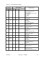
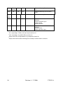
Operational Checkout
This section describes basic functional
testing.
Removal
1. At the trigger wire post adjacent to the
flashtube, remove the large diameter
wire coming from the trigger
transformer.
2. At one of the smaller, side-mounted
ceramic posts, remove the small wire
to the trigger transformer. Do not
disconnect the primary winding wires.
3. Remove the two 4-40 x 2" Phillips®head screws holding the transformer
assembly to the bracket. Note the
orientation of the molded secondary
winding with respect to fixed features
on the bracket, since it must be
reinstalled with this same orientation.
Observe the response of the equipment as
indicated in Figure 3-1. If the system
contains more than one light, and the
lights are interconnected for master/slave
synchronization, perform the actual
checkout steps described below only at the
master unit. However, observe all lights
for responses. These procedures assume
that the following conditions are present:
1. The photocell is subjected to normal
outdoor daylight.
2. All installation steps in Installation
Checklist have been completed.
3. PCB1 is correctly programmed.
4. Remove the outer half of the core and
lift off the molded secondary winding.
The primary winding will remain
hanging in place.
5. Remove the inner half of the core.
28
Revision 4 – 1-7-2008
FTB 312-4
Normal Operation
Indicator
Day
Night
Dual
System
Night
Function Description
I15
NITE ERR – On for night intensity error.
OFF
OFF
OFF
I9
DAY ERR – On when a day intensity error has
occurred (light flashed at the incorrect intensity).
OFF
OFF
OFF
I14
PEC ALARM – On for Photocell alarm (Photocell
failed to switch state).
OFF
OFF
OFF
I8
WHT ALM – On when a white alarm occurs (white
light failed).
OFF
OFF
OFF
I13
RED ALARM – On for optional red alarm (red light
failure occurred).
OFF
OFF
OFF
I7
MRK ALM – Not used.
OFF
OFF
OFF
I12
FAN – Not used.
NOT
USED
NOT
USED
NOT
USED
I6
SYNC – Flicks on every six seconds.
FLICK
FLICK
FLICK
I11
CONFIRM – On when PCB1 detects a valid flash.
I 5 flickers at flash rate.
FLICK
FLICK
OFF
I5
DAY – On when power converter is in day mode.
ON
OFF
OFF
I10
NITE – On when the power converter is in night
mode.
OFF
ON
ON
I4
MKRS – On when the power converter is in night
mode.
NOT
USED
NOT
USED
NOT
USED
I3
TRIGGER POWER – Indicates 120 VDC trigger
voltage is available.
ON
ON
ON
Figure 3-1 – Function Indicators
FTB 312-4
Revision 4 – 1-8-2008
29
Manual Override: Fixed
Intensities
You may manually override automatic
intensity control (as when the manual
intensity override switch S2 is set to
AUTO), but only if no synchronization
line connects to other lights. Remove any
wire from external circuitry attached to the
master/slave interconnect terminals. Do
this either for temporary purposes (testing)
or for permanent operation at a fixed flash
intensity.
2. Check Normal Nighttime Operation:
Place an opaque (blocks all light)
cover over the photocell and verify
that the white night responses at each
power converter in the system are the
same as those shown in Table 3-2 for
Nighttime operation.
NOTE
A minute may pass before the photocell
responds to the darkened condition
after power is applied.
•
Daytime
Switch the Intensity Control Switch (S2)
to DAY
Night
Switch the Intensity Control Switch (S2)
to NIGHT.
PCB1 Indicator Lamps
Note that the strobe is flashing at
the nighttime intensity. The strobe
does not flash if a red light system
is used.
3. Check Alarm Sensing: Remove
primary power and temporarily
disconnect the black wire on TB2.
Apply primary power and verify the
following:
See Section 1 for a description of LED
indicators on the PCB1 board for system
checkout.
•
The light does not flash.
•
The WHT ALM LED (I 8) is lit
after three missed flashes.
Standard System
•
The DAY ERR LED (I 7) is lit.
The following procedures check normal
operation.
•
The alarm circuit operates
according to installation
requirements.
1. Check Normal Daytime Operation:
Apply power to the system (pull the
plunger of the interlock switch or
switches outward to the service
position). Ensure that the manual
intensity override switch or switches
are set to AUTO and verify that the
daytime responses at each power
converter in the system are the same as
those shown in Table 3-2 for Daytime
operation.
•
30
4. Restore the Equipment After
Checking: Replace all disconnected
wires. Remove the cover that you
placed on the photocell. Ensure that
the manual intensity override switch is
in the AUTO position.
5. If Any Responses are Not Normal:
If any of the responses above are not
exactly as described, proceed to
Troubleshooting.
Note that the white light is flashing
at the daytime high-intensity.
Revision 4 – 1-7-2008
FTB 312-4
Dual System (White in Daylight,
Red at Night)
The following procedures check normal
operation of a dual system, a system with
red lights operated by an external red light
controller. The external red light controller
is connected to TB5.
1. Check Daytime Operation: Apply
primary power and verify that daytime
operation is identical to that for a
standard system, step 1. Check Normal
Daytime Operation.
2. Check Nighttime Operation: Cover
the photocell and verify that the white
light is not flashing and the red lights
are be operating normally. The MKRS
LED (I 12) is off.
3. Check Alarm Sensing by Simulating
a Failure of the Red Light System:
In this step, you simulate a failure of
the red light system. In some
installations, you can do this by
removing one of the wires (red or
black) from the Red Light Controller
that connects to the RED MONITOR
INPUT at TB5-4 and TB5-5, if an
alarm is signaled by contacts that open
in the red light controller. See Figure
2-5 and Figure 2-6. Verify the
following:
5. If Any Responses are Not Normal:
If any of the responses above are not
exactly as described, proceed to
Troubleshooting.
Intensity stepping is controlled by a
photocell. For testing, the photocell should
be exposed to normal outdoor daylight.
Figure 1-2 gives the location of the
indicator lamps on the board, while Figure
4-1 shows the location of the board within
the power converter.
6. Verify Daytime Operation: Use the
procedure in 1. Check Normal
Daytime Operation for testing the
power converter.
7. Verify Nighttime Operation: Use the
procedure in 2. Check Normal
Nighttime Operation for testing the
power converter.
Troubleshooting
Careful observation of operation often
leads directly to a symptom cause.
System-level problems affect all lights in a
multiple-light system in the same way.
Unit-level problems originate in a single
light.
However,
some
unit-level
malfunctions can affect the entire multilight system. Use Figure 3-2 for
troubleshooting a single unit and Figure 33 for the system.
•
The system resumes strobe
flashing (at night intensity).
•
The WHT ALM LED (I 8) is not
lit.
When you trace a problem to a specific
component, see Component Testing and
Component Removal and Replacement for
further assistance.
•
The RED ALM LED (I 3) is lit.
Master Unit
•
The alarm circuit operates
according to installation
requirements.
A stand-alone unit is a single FTB 312-4.
A master unit is similar to a stand-alone
unit, except that it is the controlling unit in
a multiple-light system. A master unit has
the photocell connected and, in a multiplelight system, is the controlling unit with
synchronization wires connected at the
4. Restore the Equipment After
Checking: Replace all disconnected
wires. Remove the cover that you
placed on the photocell.
FTB 312-4
Revision 4 – 1-8-2008
31
master/slave interconnect terminals at
TB1-4 and TB1-5.
1. Temporarily disconnect the black
master/slave interconnect wire at TB14.
2. Temporarily set the manual intensity
override switch S2 to DAY.
3. Verify the Daytime responses are the
same as those in Table 3-2 and Section
1. Check Normal Daytime Operation
on Page 3-7.
4. Verify that the strobe is operating at
daytime intensity (high intensity).
5. Check the synchronization signal at the
black TB1-4 master/slave interconnect
terminal with a voltmeter as in Sync
Signal Evaluation. Use the intensity
control switch to step the unit from one
intensity to the other, or cover and
uncover the photocell. If the
synchronization signal is absent,
replace PCB1. A signal response could
indicate a slave unit problem or RFI
(see Slave Unit, and RFI Problems).
pulse must be present as described in
Sync Signal Evaluation. Check wiring
if sync is not present.
4. Select NIGHT at the manual intensity
override switch. The unit will go into
night mode with the strobe flashing at
night intensity (low intensity). Note
that if a red system is used, the white
strobe does not flash at night.
5. Check the signal on the master/slave
interconnect wire at TB1-4 with a
voltmeter, as described in Sync Signal
Evaluation. An absent pulse requires
checking the system for RFI (see RFI
Problems) and for another
malfunctioning unit connected to the
master/slave interconnect wire.
6. Reconnect the master/slave
interconnect wire to TB1-4.
7. Place the manual intensity override
switch in the AUTO position.
6. Reconnect the black master/slave
interconnect wire.
7. Place the manual intensity override
switch in the AUTO position.
Slave Unit
A slave unit receives intensity information
from a master unit over the master/slave
interconnect wires at TB1.
1. Temporarily disconnect the black
master/slave interconnect wire at TB14. The unit will go into day operation.
2. Verify the Daytime responses are the
same as those in Table 3-2 and Section
1. Check Normal Daytime Operation
on Page 3-7.
3. Check the synchronization signal at the
black master/slave interconnect
terminal with a voltmeter. The sync
32
Revision 4 – 1-7-2008
FTB 312-4
Figure 3-2 – Unit Troubleshooting Guide
Flash
Conditions
Other Conditions
1
Probable Causes
2
Day
Night
HV
LV
No
No
OK
OK
No
No
No
No
No
No
No
No
F1 Fuse
S1 Interlock
T1 Transformer
Connections – Main Power
No
No
No
OK
C2A-D or C3 Shorted
Shorted FH Cable
No
No
OK
No
No indicators lit
on PCB1
OK
High
Intensity
OK
OK
Red Alarm
OK
OK
OK
OK
Markers Out
F4 Fuse
3
K5 Marker Control Relay
PCB1 Board
OK
OK
OK
OK
Markers Stay On
K5 Marker Control Relay
PCB1 Board
OK
Backup
Intensity
OK
OK
OK
OK
OK
OK
-
-
OK
OK
No
FTB 312-4
OK
OK
OK
FT101 Flashtube
Flashhead Cable Connections
T101 Transformer
4
Flashtube Mounting Plate Assembly
T1 Transformer
T3 Transformer
BR1 Bridge
PCB1
Blows Fuse F1
Varistor MOV
T1 Transformer
PCB1 Board
T1 Power Transformer
BR1 Bridge
PCB1 Board
Photocell Circuit
K2 Relay
Intensity Select Switch Setting
3
4
Flashtube Mounting Plate Assembly
K2 Relay
PCB1 Board
Marker Alarm
Incorrect Mode
Red Alarm
One or More Marker Lamps Out
3
K5 Marker Control Relay
PCB1 Board
PCB3
S2 Intensity Select Switch Not in AUTO
PEC or PEC Wiring
PCB1
C3 Capacitor
Trigger Steering Relay
4
Flashtube Mounting Plate Assembly
Revision 4 – 1-8-2008
33
4
OK
Backup
Intensity
OK
OK
Flashtube Mounting Plate Assembly
F5
Red
OK
OK
OK
Flashtube Mounting Plate Assembly
PCB1
Red
or
White
OK
OK
OK
White Alarm
OK
No
OK
OK
Red Alarm
PCB1 Board
K2 Relay
C3 Burst Capacitor Open
L1 Burst Choke
R2 Burst Resistor
No
OK
OK
OK
White Alarm
PCB1 Board
K2 Relay
L2 Flash Chock
C2A-D Capacitors Open
34
4
4
Flashtube Mounting Plate Assembly
1
HV = High voltage. PCB2 or HV neon lamp lit confirms HV.
2
LW = Low voltage. Any PCB1 LED on confirms LV.
3
Replace the entire red light module if any components therein fail.
4
Replace the entire flashtube mounting plate assembly if the filter motion is defective.
Revision 4 – 1-7-2008
FTB 312-4
Figure 3-3 – System Troubleshooting Guide
Flash Conditions
Other Conditions
Probable Causes
Day
Night
OK
Day
Flash
Possible PEC Error
PEC Photocell
PCB1 Board
Intensity Select Switch
Jumper on TB1 & 2 on Slave Units Missing
Red
OK
Possible PEC Error
PEC Photocell
Intensity Select Switch
-
-
Units Mixed Red
and White
OK
OK
Units Not Flashing
Together
No
No
No Lights
FTB 312-4
Intensity Select Switch
Master / Slave Interconnect Wiring
Master / Slave Interconnect Cable Connected to TB1-4
and TB1-5
PCB1 in One Unit
Main Power Line
Revision 4 – 1-8-2008
35
Section 4 – Recommended Spare & Replaceable Parts
Customer Service
Customer Service: 1-800-821-5825
Telephone: (615) 261-2000
Facsimile: (615) 261-2600
Shipping Address:
Flash Technology
332 Nichol Mill Lane
Franklin, TN 37067
Ordering Parts
To order spare or replacement parts, contact customer service at 1-800-821-5825.
Power Converter Parts
Figure 4-1 Power Converter Major Replaceable Parts lists the major replaceable parts for the
power converter.
Flashhead Parts
Figure 4-3 lists the part numbers for the major replaceable parts
Photocell Parts
The part number for the single assembly PEC 510 Photocell is 1855001.
36
Revision 4 – 1-7-2008
FTB 312-4
Part Number
Reference
Description
BR1
Diode Bridge
6902806
C2A,C,D
Capacitor, Main Bank, 70 mfd.
6720401
C2B
Capacitor, Main Bank, 40 mfd
6386504
C3
Capacitor, Night Mode, 1 mfd.
6848202
C4
Capacitor, Tuning, 3 mfd.
6577903
F1
►Fuse, Power, MDL8
F4
Fuse, Marker, MDL5
4900345
Fuse, MDL1
4900337
HV
Neon, High Voltage Warning Light
4902317
K2
►Relay 24V, Mode
8900494
K3
►Relay 120V, Discharge
8900493
L1
Choke, Burst
4850601
L2
Choke, Flash
4175200
PCB1
►Timing and Trigger Board**
2903800
PCB2
►HV Rectifier Board
2458005
PCB4
Sense Board
2811101
PCB5
Modem Board
2903801
Resistor, Discharge
6900541
Resistor, Burst, 500 ohm
6900532
SW1
►Switch, Interlock
4901220
T1
Transformer, Power
T3
Transformer, Coupling
8336701
TB1
Terminal Strip, 18 Position
4901930
TB2, TB7
Terminal Strip, 6 Position
4902257
TB3
Terminal Strip, 11 Position
8721011
TB4, TB5
Terminal Strip, 3 Position
4902134
TB6, TB8
Terminal Strip, 3 Position
4902157
TB1-1 to TB1-2 Jumper
5901232
F5, F6
R1
R2A&B
VR1
50 Hz
4901931*
(2 Required)
8842901
Varistor
6901081
M1
Red Light Module
►Recommended as a spare part.
60 Hz
4901931*
8841201
6901079*
1181502
*This part number varies according to the specific equipment voltage configuration.
**Please specify the model number of the equipment when calling for a replacement.
Figure 4-1 – Power Converter Major Replacement Parts
FTB 312-4
Revision 4 – 1-8-2008
37
Figure 4-2 – Power Converter Component Layout
38
Revision 4 – 1-7-2008
FTB 312-4
Reference
Description
Part Number
Ceramic Spacer, ¾” diameter
5900844
Ceramic Spacer, ½” diameter, short
5900842
Ceramic Spacer, ½” diameter, tall
5900843
FT101
Flashtube
8384308
A101
Flashtube Mounting Plate Assembly
8812405
RC101
R.C. Network
1403411
RC102
R.C. Network
1403412
T101
Transformer, Trigger
8288201
T102
Transformer, Coupling
8336701
P1,P2,P4,P5,P12
P3,P11
P6,P7,P8
Figure 4-3 – Flashhead Major Replacement Parts
FTB 312-4
Revision 4 – 1-8-2008
39
P15
P16
P13
BR102
LOCATED ON ANGLED
TAB, UNDER MP101
10
1
SW101
(BOTTOM)
C102
BR101
SW102
(TOP)
C
P14
L101
T101
TRIGGER
TRANSFORMER
FLASHTUBE
LUG
SHIELD
GROUND
SCREW
CATHODE
MP101
P7
ANODE
01
P1
CLUTCH
P6
RC
1
ED
R
RC102
P2
TRIGGER
RING
FILTER
FLASHTUBE
SUPPORT
B101B
MOTOR
U
BL
P3
T102
K
BL
COUPLING
TRANSFORMER
P4
P5
T
H
W
O
VI
Figure 4-4 – Flashhead Component Layout
40
Revision 4 – 1-7-2008
FTB 312-4
Returning Equipment – Return Material Authorization (RMA)
If a product purchased from Flash Technology must be returned for any reason, please follow
the procedure below:
NOTE: An RMA number must be requested from Flash Technology prior to shipment of any
product. No returned product will be processed without an RMA number. This number will be
the only reference necessary for returning and getting information on the product’s progress.
1. To initiate an RMA, customers should call the Alarm Response & Compliance Center at
(800-821-5825) to receive technical assistance and a case number. The following
information is required before a case number can be generated:
•
Site Name/Number / FCC Registration number/ Call Letters or Airport Designator
•
Site Owner (provide all that apply – owner, agent or subcontractor)
- Contractor Name
- Contractor Company
•
Point of Contact Information: Name, Phone Number, Email Address, Fax Number
and Cell Phone (or alternate phone number)
•
Product’s Serial Number
•
Product’s Model Number or part number
•
Case Number (if previously given)
•
Reason for call, with a full description of the reported issue
2. The case number will then serve as a precursor to receiving an RMA number if it is
determined that the product or equipment should be returned. To expedite the RMA
process, please provide:
•
Return shipping method
•
Purchase Order (if non-warranty repair)
•
Shipping Address
•
Bill To Address
•
Any additional information to assist in resolving the issue or problem
3. A P.O. is required in advance for the replacement of product that may be under warranty.
Flash will then, at its discretion issue a credit once the validity of the warranty has been
determined.
4. A purchase order (P.O.) is also required in advance for all non-warranty repairs. NOTE:
the purchase order is required prior to the issuance of the RMA number.
•
If the P.O. number is available at the time of the call, an RMA number will be issued
and the customer must then fax or email the P.O. with the RMA number as the
reference, to ensure prompt processing.
FTB 312-4
Revision 4 – 1-8-2008
41
•
If the P.O. number is NOT available at the time of the call, a Case Number will be
given to the customer and should be referenced on the P.O. when faxed or emailed to
RMA Rep.
•
Flash will then, at its discretion repair or replace the defective product and return the
product to the customer based on the shipping method selected.
•
The customer may purchase a new product before sending in the existing product for
repair. If Flash Technology determines the existing product is still covered under
warranty a credit will be issued to the customer for the new product.
5. After receiving the Flash Technology RMA number, please adhere to the following
packaging guidelines:
•
All returned products should be packaged in a way to prevent damage in transit.
Adequate packing should be provided taking into account the method of shipment.
Flash Technology will not be responsible for damaged items if product is not
returned in appropriate packaging.
6. All packages should clearly display the RMA number on the outside of all RMA shipping
containers. RMA products (exact items and quantity) should be returned to:
Flash Technology
Attn: RMA #XXX
332 Nichol Mill Lane
Franklin, TN 37067
7. All RMA numbers:
•
Are valid for 15 business days. Products received after may result in extra screening
and delays.
•
Must have all required information provided before a RMA number to be assigned.
Return to Stock Policy
•
Parts can be returned within 90 days of ship date and will be subject to a 20% restocking
fee. Product must:
- Be in the original packaging
- Not be damaged
•
42
After 90 days no parts can be returned
Revision 4 – 1-7-2008
FTB 312-4