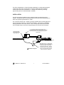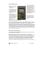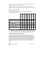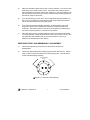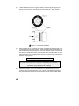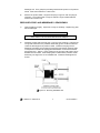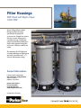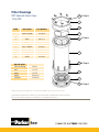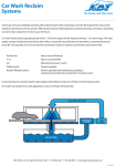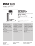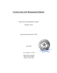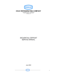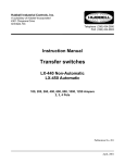
1
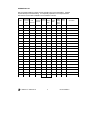
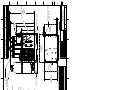
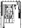
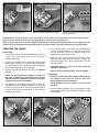
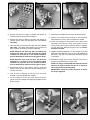
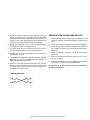
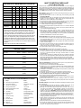
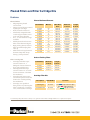
Village Marine LT-5000 Part Number: 95-0022 LT Watermakers LT 3000-7000 GPD Installation, Operation & Maintenance The following are the types of flags used in this technical manual. They designate safety related items and important operational instructions and should be given special attention when they appear in the text: WARNING CAUTION NOTE Text formatted in this manner concerns an operating procedure or practice that, if not strictly observed, can result in injury to personnel or loss of life. Text formatted in this manner concerns an operating procedure or practice that, if not strictly observed, can result in damage to or destruction of equipment. Text formatted in this manner concerns an operating procedure or condition that warrants special attention MODEL: __________________________________ SERIAL NUMBER: __________________________ DATE OF PURCHASE: ______________________ PURCHASED FROM: _________________________________ INVOICE #: __________________________________________ VESSEL NAME: ______________________________________ INSTALLED BY: ______________________________________ DATE OF INITIAL STARTUP: ____________________________ i LT Watermakers 3000 to 7000 GPD (11 to 27 m3/day) Practical and Reliable Fresh Water Supply The LT desalinator offers a simple watermaker package with a compact frame and small footprint. Racor VMT LT systems have a base frame only 40” wide x 33” deep, allowing a high capacity and high quality watermaker installation in a tight space. Village Marine LT-5000 Contact Information: Parker Hannifin Corporation Racor Division/Village Marine Tec. 2000 W. 135th St. Gardena, CA 90249 phone: 310 516-9911 800 C-Parker fax: 310 538-3048 email: [email protected] www.villagemarine.com www.parker.com/racor Key Feature - Installation Flexibility: LT units can be supplied with an optional media filter system. Also membrane rack can be mounted horizontally or as a module for remote bulkhead mounting. LT Watermakers 3000 - 7000 GPD (11 to 27 m3/day) Standard Features: • Stainless steel high pressure pump is resistant to the corrosive seawater environment • Fiberglass cartridge filter hosing holds 100 square foot 5 micron element Model • Marine bronze low pressure pump provides up to 50 psi of boost pressure to the filtration system • Glycerine filled pressure gauges • Flowmeters to monitor freshwater and reject rates • Freshwater flush system included standard • 316 stainless steel pressure regulator is adjustable to allow operation in brackish or fresh water • Electrical control panel Nema 4X with motor starter and pump controls • Automatic diversion valve diverts water to overboard if quality drops below acceptable standards • Digital water quality monitor displays purity of product water produced Part Number* Power Volts/ phase/Hz/Amps Dimensions** inch/cm Capacity GPH-m3/Day Weight lbs/kg 90-6057 90-6059 90-6058 90-6060 90-6062 90-6061 220/1/60/53 440/3/60/17 380/3/50/17 width 40/102 depth 39/99 height 62/157 125/11 1060/480 220/1/60/53 440/3/60/17 380/3/50/17 width 40/102 depth 39/99 height 62/157 167/15 1080/490 LT-5000 90-6063 90-6031 440/3/60/22 380/3/50/24 width 40/102 depth 39/99 height 62/157 208/20 1140/520 LT-7000 90-6065 90-6064 440/3/60/22 380/3/50/24 width 40/102 depth 43/109 height 62/157 292/27 1290/585 LT-3000 LT-4000 * Add part number 90-0264 to include optional media filter. **Includes membrane rack mounted vertically. Does not include boost pump or optional media filter that increase width to 56/142. Spares and Consumables Part No. Description 33-5100 Filter Cartridge - 5 micron 30-0405 O-Ring Seal - Filter Housing 33-0315 Carbon Flush Filter Element 70-1448 Drive Belt - Check for Exact Size 85-0050 Pump Oil - Quart Bottle 90-2323 Membrane O-Ring Kit (up to LT-5000) 32-1016 Membrane O-Ring Kit (LT-7000) Part No. 40-0241 33-0440 33-0036 85-0045 85-0048 85-0049 Description Salinity Probe RO Membrane (up to LT 5000) RO Membrane (LT-7000) Membrane Cleaner #1, 25 lbs. pail Membrane Cleaner #2, 25 lbs. pail Membrane Preservativ, 25 lbs. pail WARNING – USER RESPONSIBILITY FAILURE OR IMPROPER SELECTION OR IMPROPER USE OF THE PRODUCTS DESCRIBED HEREIN OR RELATED ITEMS CAN CAUSE DEATH, PERSONAL INJURY AND PROPERTY DAMAGE. • This document and other information from Parker-Hannifin Corporation, its subsidiaries and authorized distributors provide product or system options for further investigation by users having technical expertise. • The user, through its own analysis and testing, is solely responsible for making the final selection of the system and components and assuring that all performance, endurance, maintenance, safety and warning requirements of the application are met. The user must analyze all aspects of the application, follow applicable industry standards, and follow the information concerning the product in the current product catalog and in any other materials provided from Parker or its subsidiaries or authorized distributors. • To the extent that Parker or its subsidiaries or authorized distributors provide component or system options based upon data or specifications provided by the user, the user is responsible for determining that such data and specifications are suitable and sufficient for all applications and reasonably foreseeable uses of the components or systems. © 2011 Parker Hannifin Corporation Print Reorder Number VMT0001 Rev- 07-25-2011 The Racor Village Marine LT series Seawater Desalinator is a single-pass purification system that uses reverse osmosis (RO) to produce potable water from seawater. Product water with salt concentrations of < 500 ppm are achieved by removing approximately 99% of the dissolved salt in seawater. INSTALLATION The RO unit should be installed in a dry, sheltered location protected from direct weather. Drainage should be provided beneath the RO unit to allow standing water to drain when performing maintenance or repair. The connection sizes are all 1” flanges, except the seawater feed connecting directly to the LP boost pump inlet with a 1.25” FNPT thread fitting. Consult the LT installation drawing towards the end of this manual. The LP boost pump should be below water line for flooded suction, and can be relocated away from the main unit if necessary. Reject discharge line overboard and above water line. It is important that the product water line is connected to the top of the storage tank to prevent chlorinated water from siphoning back into the watermaker. Boost pump below water line with flooded suction. Installation Diagram LT-3000 to LT-7000 Manual 1 Raw water inlet, 1.5” through-hull with sea cock, low as practical and towards the back of the vessel, but forward of the drive. Planing hulls may need a forward facing scoop if the watermaker operates while the vessel is underway. Revised 03/2012 CAUTION Inlet and discharge piping should be constructed of a NON-FERROUS material. Examples of some suitable materials are PVC, copper-nickel, 316 stainless steel piping or a reinforced non-collapsing hose. Ferrous piping introduces iron that will foul the membranes prematurely. NOTE Avoid connecting the seawater source to a water line that services any other piece of equipment. Air could be drawn through the RO unit causing damage to the RO unit's pumps. Cross contamination is also possible. The best practice is a dedicated through hull for the watermaker, with a separate seacock and strainer. Connect electrical power to the watermaker. Select the circuit breaker size of at least 50% more than the operating amps shown on the serial number tag. Connect power to the main terminal block in the electrical enclosure. Three phase power supplies will spin the motors and pumps either rotation direction, depending on the phase sequence of the three hot power legs. The HP pump should rotate counterclockwise from the pulley end and low pressure pumps are marked with a direction of rotation. It is important not to rotate the low pressure pump backwards. Even “bumping” the motor for a few seconds can loosen the impellor and cause damage. The high pressure pump will not be damaged from running backwards. Therefore, always use the high pressure pump only to check rotation and adjust the input power legs accordingly prior to checking the low pressure pump. If the low pressure pump is inadvertently “bumped” backwards, open the pump and check the impellor is secured on the motor shaft and spins freely prior to starting it again. CAUTION Strictly observe all applicable electrical codes and regulations governing the installation and wiring of electrical equipment. Typical codes specify the type and size of conduit, wire diameter and class of wire insulation depending upon the amperage and environment. The power supply should always be of a greater service rating than the requirements. Never connect the RO unit to a supply that services another electrical device, the RO unit should have its own breaker or disconnect. WARNING Disconnect electrical power to RO unit prior to servicing the watermaker. LT-3000 to LT-7000 Manual 2 Revised 03/2012 STARTUP AND OPERATING PROCEDURE 1) Check the HP pump oil level by observing sight gauge located on the pump. On initial start-up, the media filter may need to be loaded, and the membranes installed. Open the raw saltwater supply to the unit at the through-hull. The flushing valve V10 is in the saltwater position and the cleaning valve V5 should be in the normal position. 2) Verify the bypass valve V4 (black handle) is open, counterclockwise. 3) Start the LP pump, verify the filter pressure gauge PG1 shows > 10 psi indicating the system is primed with water. 4) Start the HP pump. Water should now be visible flowing through the reject flowmeter and discharging through the overboard reject line. 5) Slowly close the bypass valve, and confirm that the membrane pressure gauge PG2 registers 800 psi. The high pressure setting can be adjusted by turning the top adjusting bolt on the top of the high pressure regulator V3 behind the instrument panel. 6) Check the salinity reading, on the water monitor. Normal saltwater startup conditions produce salty water for the first 2 or 3 minutes. Gradually the monitor should show lower values, drinking water quality is commonly accepted as below 500 ppm. When the quality is below 500, the product solenoid valve will automatically open, and start fresh water supply through the product flowmeter and to the storage tank. 7) Now would be a good opportunity to make an operation log entry of the pressures, flow and salinity. 8) For shutdown, reverse the steps. First open the black bypass valve V4. Then shut down the HP and LP pumps. If you are unsure if the watermaker will be restarted in a day or so, now is time to flush the watermaker to keep the membranes fresh while idle - please see the next section. Bacteria and biologic growth increases the longer stagnant water is in contact with the membranes, so the flushing is advised whenever the unit will be idle. Once flushed, the flush should be repeated once every one or two weeks if the idle period continues. For extended periods, see the section on pickling or preserving the watermaker. LT-3000 to LT-7000 Manual 3 Revised 03/2012 MONITOR INSTRUCTIONS FRESH WATER FLUSH PROCEDURE Make sure the black handled bypass valve V4 is open (counter clockwise), and then turn the three way flushing valve V10 so the handle to the flushing position. The carbon filter scrubs chlorine that might be in your tank water, so the membranes are not exposed to any chlorine. Now fresh water is running through the system, you can start the high pressure pump and run for two minutes. After two minutes, stop the pump and turn the flushing valve back so the handle is pointing away from the flushing filter. If the fresh water supply line is not sufficient to run the pumps, then extend the flushing time. The goal is displace all water in the cartridge filter housing and the membrane vessels with fresh water – about 30 gallons. MEDIA FILTER SYSTEM (OPTIONAL) LT units supplied with a media filter require initial media filling as per the fill instruction page at the very back of this manual. The media filter is fitted with a top mount multiport valve, V11, with SERVICE, BACKWASH and RINSE settings. The valve connections are with the filter inlet to the back of the bronze valve, the filtered water outlet to the right, and the backwash drain to the left. Frequency of backwash will depend on seawater turbidity and installation characteristics. As a starting point, backwash the media filter when the differential pressure at PG4 is 12 psi or every 24 operation hours. The RO must be off to backwash the media filter and the media bypass valve must be in the normal position LT-3000 to LT-7000 Manual 4 Revised 03/2012 (not bypass). Start only the LP boost pump, and run for 5 minutes in the backwash position and then 3 minutes in the rinse position. When the watermaker is not being used, the media filter should be backwashed whenever the RO is flushed. Regular backwash will minimize organic growth inside the tank. MAINTENANCE INSTRUCTIONS Labor Hours (approximate) 0.5 Check pump oil level Annually Replace filter element when filter pressure is 10 psi lower than clean element Quarterly 0.5 Monthly Weekly Clean and inspect micron filter Each Start As Required Semi-Annually Adapt the following suggested routine maintenance schedule as required to your installation and operating conditions: 0.1 Backwash media filter 0.2 Change pump oil after first 50 hours 1.0 and then based on usage * Lubricate HP pump motor at grease nipple with one stroke bearing 1.0 grease *Oil change should be monthly with the constant 24/7 usage. For installations under heavy use (8 hours per day average), change every 3 months. For installations where the watermaker is for back-up, emergency or special missions, oil change should be once every year. Oil change at approximately every 500 hours. MEMBRANE CLEANING AND PRESERVATION During normal operations, mineral scale and biological matter will slowly foul the RO membranes. These deposits build up over time and will eventually cause a loss of product water output, salt rejection capability, or both. The RO elements should be cleaned when product water output drops by 15% from the initial baseline established during the first hours of operation with new membranes. Chemical cleaning is usually not effective if fouling has dropped production below 80% of the original condition. Chemical cleaning can recover lost flow rate, but is less effective recovering lost salt rejection. LT-3000 to LT-7000 Manual 5 Revised 03/2012 Preservation or pickling is done to protect the membranes during long term storage. A properly pickled system will stay fresh for 6 months in temperate climates or 4 months in the tropics, after which it needs to be flushed and the preservation process repeated. The basic procedure for all cleaning and preservative treatments is the same - a specific chemical solution is loaded in the cartridge filter tank and circulated through the system for 20 minutes and then flushed out. Cleaner #1 is an alkaline detergent is used to remove biological matter and grime from the surface of the RO membranes. Cleaner #2 is an acid cleaner is used to remove mineral scale deposits. Use #1 first in most cases to better remove biological fouling. Use #2 first in special cases where hardness scaling or iron deposits are known to be the primary foulant. The preservative or pickling chemical is labeled as Chemical #3. Cleaner LT3000-7000 Cleaning Chemical #1, part 85-0045 5 to 15 lbs (8 to 25 cups) Cleaning Chemical #2, part 85-0048 4 to 12 lbs (7 to 20 cups) Preservative Chemical #3, part 85-0049 4 lbs (6 cups) Chemical Requirements Dissolve the appropriate amount powder in a pail of fresh water. Make sure that that the chemical is completely dissolved (use warm water if necessary). There is a large variance in the required amount of chemical due to several factors. If RO product water is used to flush the unit prior to cleaning, the quantity required will be on the lower side. If the fresh water flush is done with dock or city water that is hard, then the required amount will rise. If the unit is significantly fouled, the quantity also rises. The key is to use only enough chemical to achieve the desired pH (pH 11 for #1 and pH 3 for #2). Extreme pH will damage the membranes, so do not exceed the recommendations. For the first cleaning of a system, use the lower quantities and measure the pH after circulating as described below. Keep adding chemical as needed until the cleaning solution maintains the desired pH level. Keep a record of the total chemical needed, so that on subsequent cleanings the correct amount can be used without the needed pH measurements and adjustments. Use the following procedure for cleaning or preservation: 1) Flush the watermaker, so that the chemical works in fresh water not saltwater. 2) Remove the cartridge filter housing lid, and pour in the mixed chemical. Leave the filter cartridge in place and replace the lid. 3) Turn the cleaning valve V5 to the cleaning position. LT-3000 to LT-7000 Manual 6 Revised 03/2012 4) Make sure the black bypass valve is open, counter clockwise. Turn the over-ride slide switch on the water monitor to OFF. Temporarily open the flush valve to allow fresh water to boost the cleaning loop pressure. In may be necessary to do this several times after the pump is running, watch the filter pressure gauge PG1. Run the HP pump for 20 minutes 5) If you are preserving, you are done. On the initial restart after preservation, run the unit for 10 minutes prior to switching the water monitor slide switch back to auto to clear all the preservative from the system. 6) If you have just finished circulating cleaner #1, conduct the flesh water flush sequence to purge out the chemical and repeat the circulation process with cleaner #2. The cleaning valve V5 must be in normal position for flushing and then back to cleaning position to circulate the next cleaner 7) After both cleaners have circulated and been flushed out, reset the watermaker for normal operation. Reset the slide switch on the water monitor to AUTO. Run the watermaker with seawater and record the performance in your log to determine the effectiveness of the cleaning. PRESSURE VESSEL AND MEMBRANES - DISASSEMBLY 1) Disconnect all plumbing connections from the pressure vessel to be disassembled. 2) Remove the bolts holding each end plug in place with an Allen wrench. Place a mark on each end plug removed and its corresponding collar. This will ensure proper orientation during assembly. JACKING SCREW HOLES Figure 6.0 - Pressure Vessel End Plug LT-3000 to LT-7000 Manual 7 Revised 03/2012 3) Locate the jacking screws on opposite sides of the end cap (see Figure 6.0). Screw in the correct size bolt until the end cap is pulled off. There are also prying slots on either side of the end plug to assist in removal. Figure 6.1 - Brine Seal Orientation 4) After end caps are off, note which end of the membrane has the brine seal. This is the feed end of the pressure vessel. When reinstalling the RO membrane, the brine seal must be located at the feed end of the pressure vessel. Note the feed flow direction marked by a sticker on the outside of the pressure vessel, or trace the flow direction from the high pressure pump to confirm the high pressure flow direction. See Figure 6.1. CAUTION Never force a membrane out of a pressure vessel by applying pressure on the product water tube (center tube) as this will damage the membrane. If the membrane is difficult to remove, use a length of 2" plastic pipe to apply pressure on the protected end of membrane. 5) Whenever possible, remove the membrane from the discharge end of the pressure vessel (opposite the brine seal). This is accomplished by pushing on the membrane from the feed end of the pressure vessel until it is visible at the LT-3000 to LT-7000 Manual 8 Revised 03/2012 discharge end. Then grasp the protruding membrane and pull it out of pressure vessel. Place the membrane in a clean area. 6) Remove the product water o-rings and end plug o-ring from each end plug for inspection. The product water o-rings are internal o-rings located inside the center hole in the end cap. PRESSURE VESSEL AND MEMBRANES - REASSEMBLY 1) Clean all parts thoroughly. Inspect the o-rings on all fittings. Replace any parts that are damaged. NOTE Do not apply Teflon tape or other sealant to straight thread fittings such as those used on HP hose assemblies and their adapters. 2) Install the product water and end plug o-rings onto the end plugs. Lubricate the o-rings and entrances to the pressure vessel with glycerin or silicone lubricant. Locate the discharge end of pressure vessel. Install the end plug into the discharge end making sure to align the end plug holes and the mounting studs on the pressure vessel while paying particular attention to the reference mark (see Section 6.3.1, Step 2). Apply pressure to the end plug until screws can be threaded into the collars. If the end plug will not slide into the pressure vessel sufficiently, see Figure 6.2 for an installation aid. Install and hand tighten the screws. Figure 6.2 - End Plug Installation Aid LT-3000 to LT-7000 Manual 9 Revised 03/2012 3) Lubricate the brine seal and product water tubes of RO membrane with glycerin or silicone lubricant. Do not use a petroleum based lubricant. Orient the membrane such that the end without the brine seal enters the feed end of the pressure vessel first. Slide the membrane into the pressure vessel until resistance is felt. Continue to apply moderate pressure until the product water tube seats in the end plug. 4) Install the remaining end plug making sure to align the end plug holes with the mounting studs on the pressure vessel while paying particular attention to the reference mark (see Section 6.3.1, Step 2). Apply moderate pressure to the end plug until the screws can be threaded into the collar. If the end plug will not slide into the pressure vessel sufficiently, see Figure 6.2 for installation aid. Install and hand tighten the nuts. 5) Make sure that antiseize compound is applied to each screw before the final tightening and torque the screws to 15 ft-lbs. 6) Reconnect all plumbing connections to pressure vessels. LT-3000 to LT-7000 Manual 10 Revised 03/2012 OPERATION LOG We encourage operators to keep a simple operation log for the watermaker. Regular entries will help in troubleshooting. It is especially important to record performance after the first 3 hours after installation so the baseline is known. Date Media Filter Product Membrane Pressure In Filter Pressure Reject Pressure / Out Pressure Flow LT-3000 to LT-7000 Manual 11 Product Flow Water Quality TDS (ppm) Water Temp, Comments Revised 03/2012 8 7 14.75 12.25 MEDIA FILTER R.O. MEMBRANES 5 33.00 SEE NOTE FEED PUMP 24" SIDE SERVICE CLEARENCE 4 4 ` .030 ` .06 24" AND OVER WELDMENT ` .12 ` .06 ` .06 TOL ER ANCE 3 U NLESS OTHERWISE SPECIFIED ANGUL AR ` 0~ 30' ` .015 ` .03 6" TO 24" 125 3 PL ` .010 2 PL ` .02 UNDER 6" MACHINED DIMENSION MB DATE - 02/18/11 MB DATE - 01/25/12 GA DATE - 01/25/12 MM-DD-YY CONTRACT NO ISSUE DATE APPROVED - CHECKED - DRAWN - 2 SIZE 3.50 CAGE NO 22202 DWG NO 1 1 OF 1 B REV MOUNTING HOLES 0.50 (4 X 3.5) LT 3000 - 7000 INTERFACE AND MAINTENANCE ENVELOPE A 62144 SIZE 24" SIDE SERVICE CLEARENCE .75 INSTRUMENTS LT-3000 TO 5000 63.50 LT 7000 66.50 APPROVED OT AK 1 C D E F G H A 1 5 4 LARGE MEMBRANE VESSELS 42" OVERALL DEPTH 4 MEMBRANE VESSELS 39" OVERALL DEPTH 5 MEMBRANE VESSELS AS SHWN 39" DEPTH DIMENSI ONAL TO LERANCES - UNLESS OTHERWISE SPECIFIED VMT MGT A PPROVAL - 24"FRONTAL SERVICE CLEARANCE 56.00 40.00 32.00 44.50 61.50 CONTROL BOX 2 REVISION HISTORY RE DESCRIPTION DATE - INITIAL RELEASE 02/18/11 B UPDATED PER PRODUCTION 01/25/12 3 22202 6 LT-3000 LT-4000 LT-5000 LT-7000 28.75 3 MEMBRANE VESSELS 39" OVERALL DEPTH 18.25 NOTE: 2.50 13.25 23.50 INLET FROM LP PUMP FRESH WATER INLET OUT TO MEDIA FILTER INLET FROM MEDIA FILTER 6 DWG N O A REJECT OUT PRODUCT OUT 7 62144 B C D E F G H 8 CAGE N O SH 8 POWER IN 220/380/440 VAC 3 PHASE 50/60 Hz MS1 7 7 T1 L1 M1 T2 L2 T3 L3 MS2 6 T1 L1 6 M2 T2 L2 T3 L3 H4 H1 5 XFMR1 5 X4 X1 HOT COM FUSE 1 4 MC2 AUX PS1 4 14 12 12 14 X1 X1 X2 X2 14 14 ` .030 ` .06 24" AND OVER ` .12 ` .06 ` .06 3 UNLESS OTHERWISE SPECIFIED ANGULAR ` 0~ 30' ` .015 ` .03 6" TO 24" WELDMENT TOLERANCE CONTRACT NO DATE - 04/12/11 04/15/11 MM-DD-YY DATE - DATE - ISSUE DATE MB OT APPROVED - CHECKED - DRAWN - 2 SIZE CAGE NO A 62144 SIZE 96 2 - 1 - DWG NO 22250 1 2 - REV REVISION STATUS OF SHEET 1 OF ELECTRICAL SCHEMATIC 3PHASE SUPPLY LT - 3000 TO LT - 7000 MC2 96 C D E F A 1 125 3 PL ` .010 2 PL ` .02 A1 MC1 G H 22250 UNDER 6" 13 13 A1 APPROVED 1 DWG NO DIMENSION MACHINED DIMENSIONAL TOLERANCES - UNLESS OTHERWISE SPECIFIED VMT MGT APPROVAL - 13 SW4 11 SW3 11 SW1 13 SW2 110 VAC 2 REVISION HISTORY REV DESCRIPTION DATE - INITIAL RELEASE 4/15/2011 3 62144 A B C D E F G H 8 CAGE NO SH 8 7 MS1 T1 L1 M1 T3 L3 MS2 6 6 T1 L1 M2 T3 L3 5 5 4 MC2 AUX PS1 4 13 SW4 11 SW3 11 SW1 13 SW2 X1 X2 X2 14 14 13 13 ` .030 ` .06 24" AND OVER ` .12 ` .06 ` .06 3 UNLESS OTHERWISE SPECIFIED ANGULAR ` 0~ 30' ` .015 ` .03 6" TO 24" WELDMENT TOLERANCE CONTRACT NO DATE - 04/12/11 04/15/11 MM-DD-YY DATE - DATE - ISSUE DATE MB OT APPROVED - CHECKED - DRAWN - 2 SIZE CAGE NO 96 96 1 - 2 - DWG NO 22250 2 1 OF ELECTRICAL SCHEMATIC 1 PHASE SUPPLY LT-3000 TO LT-7000 A 62144 SIZE MC2 MC1 2 - REV REVISION STATUS OF SHEET C D E F G H A 2 125 3 PL ` .010 2 PL ` .02 UNDER 6" A1 A1 APPROVED 1 22250 DIMENSION MACHINED DIMENSIONAL TOLERANCES - UNLESS OTHERWISE SPECIFIED VMT MGT APPROVAL - 14 12 12 14 X1 110 VAC 2 REVISION HISTORY REV DESCRIPTION DATE INITIAL RELEASE 4/15/2011 3 DWG NO A POWER IN 220 VAC 1 PHASE 50/60 Hz 7 62144 B C D E F G H 8 CAGE NO SH 20 48 12 11 4 5 45 42 27 28 26 29 3 41 40 7 8 10 6 1 9 47 25 24 20 5 4 22 21 29 26 36 37 41 40 47 38 39 31 32 33 30 34 14 43 13 19 44 15 16 17 18 23 1 3 28 27 35 2 46 48 12 11 PARTS LIST - LT-3000 to LT-7000 Callout 1 2 3 4 5 6 7 8 9 10 11 12 13 14 15 16 17 18 19 20 21 22 23 24 25 26 27 28 29 30 31 32 33 34 35 36 37 38 39 40 41 42 43 44 45 46 47 48 LT-3000 LT-5000 LT-5000 LT-7000 LT-7000 PID Tag 440/3/60 440/3/60 380/3/50 440/3/60 380/3/50 P2 70-1257 70-1257 70-1257 70-1257 70-1257 70-1290 70-1290 70-1290 70-1290 70-1290 M2 20-0062 20-2333 20-2333-50 20-2333 20-2333-50 P1 70-1251 70-1251 70-1251 70-1251 70-1251 M1 20-0234 20-0234 20-1259 20-0234 20-1259 70-0808 70-0808 70-0808 70-0808 70-0808 70-2830 70-0040 70-0014 70-0040 70-0014 70-1121 70-1055 70-1054 70-1055 70-1054 70-1038 70-1038 70-1038 70-1038 70-1038 70-0138 70-0035 70-0244 70-0035 70-0244 32-0444 32-0444 32-0444 32-6040 32-6040 33-0440 33-0440 33-0440 33-0036 33-0036 WQM 40-0226 40-0226 40-0226 40-0226 40-0226 SW1-4 20-1591 20-1591 20-1591 20-1591 20-1591 20-1441 20-1441 20-1062 20-1441 20-1062 20-0264 20-0264 20-0264 20-0264 20-0264 20-1015 20-1015 20-1015 20-1015 20-1015 20-0581 20-0581 20-0581 20-0581 20-0581 20-1016 20-0004 20-0004 20-0004 20-0004 MMF 33-0002 33-0002 33-0002 33-0002 33-0002 V11 60-0166 60-0166 60-0166 60-0166 60-0166 60-0028 60-0028 60-0028 60-0028 60-0028 PS1 20-0480 20-0480 20-0480 20-0480 20-0480 85-5010 85-5010 85-5010 85-5010 85-5010 85-5006 85-5006 85-5006 85-5006 85-5006 F1 30-4353 30-4353 30-4353 30-4353 30-4353 CF 33-0315 33-0315 33-0315 33-0315 33-0315 CF 33-0011 33-0011 33-0011 33-0011 33-0011 F1 33-5100 33-5100 33-5100 33-5100 33-5100 PG1,PG4 40-0016 40-0016 40-0016 40-0016 40-0016 PG3 40-0303 40-0303 40-0303 40-0303 40-0303 PG2 40-0302 40-0302 40-0302 40-0302 40-0302 V2 60-0013 60-0013 60-0013 60-0013 60-0013 V4 60-0068 60-0068 60-0068 60-0068 60-0068 SR1 40-0241 40-0241 40-0241 40-0241 40-0241 V3 60-0040 60-0040 60-0040 60-0040 60-0040 V5,10,12 60-0084 60-0084 60-0084 60-0084 60-0084 V6 20-1141 20-1141 20-1141 20-1141 20-1141 V7 60-7742 60-7742 60-7742 60-7742 60-7742 FM2 40-0211 40-0211 40-0211 40-0015 40-0015 FM1 40-0210 40-0210 40-0210 40-0210 40-0210 50-0026 50-0026 50-0026 50-0026 50-0026 20-1592 20-1592 20-1592 20-1592 20-1592 20-0684 20-0684 20-0684 20-0684 20-0684 50-0026 50-0026 50-0026 50-0026 50-0026 60-0375 60-0375 60-0375 60-0375 60-0375 P2 85-0050 85-0050 85-0050 85-0050 85-0050 90-2323 90-2323 90-2323 32-1016 32-1016 QTY 1 4 1 1 1 1 1 1 1 1 3,4,5 3,4,5 1 2 1 1 1 1 1 1 1 1 1 4 1 1 1 1 1 2 1 1 1 1 1 1 3 1 1 1 1 1 2 1 1 3,4,5 3 3,4,5 DESCRIPTION PUMP, HIGH PRESSURE MOUNT, MTR/PMP, PMT MOTOR, HP PUMP PUMP, LOW PRESSURE BOOST, NO MOTOR MOTOR, 2HP, LP BOOST PUMP PULLEY, PUMP PULLEY, MOTOR BELT, DRIVE BUSHING, PUMP, BUSHING, MOTOR PRESSURE VESSEL ASSEMBLY MEMBRANE ELEMENT MONITOR, WATER QUALITY PUSHBUTTON, DUAL, START/STOP TRANSFORMER, .150KVA, CONTACTOR, LP PUMP RELAY, OVERLOAD, 3-5 AMPS L/P PUMP CONTACTOR, HP PUMP RELAY, OVERLOAD, HP PUMP TANK, MEDIA FILTER VALVE, MEDIA, 1.5" FNPT VALVE, VACUUM BREAKER SWITCH, LOW PRESS SAND MEDIA, per pail GRAVEL MEDIA, per pail FILTER, HOUSING, 100 SQ FT, FRP FILTER ELEMENT, CARBON, 5" X 10", BW FILTER, HOUSING, 5" X 10", 1.5" FNPT FILTER ELEMENT, 5 MIC, 100 SQ FT GAUGE, PRESSURE, 0-100PSI, BACK CONN. GAUGE, PRESSURE, 0-60PSI, BACK CONN. GAUGE, PRESSURE, 0-1000PSI, BACK. CONN. VALVE, 3-WAY, 1/4" TUBE, 316SS VALVE, BALL, BYPASS, 1/2" FNPT, 316SS SALINITY PROBE VALVE, HP REGULATOR, 40 GPM VALVE, 3-WAY, 1" PVC, SIDE LOAD VALVE, SOLENOID, 120 V, 3/4" PORTS VALVE, RELIEF, 3/4" FNPT, NYL, VMT FLOWMETER, PRODUCT, 1.5"MNPT FLOWMETER, REJECT, 1.5"MNPT MANIFOLD, PRODUCT, PW3K-10K CONTACT BLOCK, START / STOP BUTTONS FUSE, TRANSFORMER MANIFOLD, REJECT VALVE, SAMPLE PRODUCT PUMP OIL MEMBRANE O-RING KITS 25PFR PLUNGER PUMP SERVICE MANUAL 25 FRAME SPLIT MANIFOLD: 2530, 2531, 2537 INSTALLATION AND START-UP INFORMATION Optimum performance of the pump is dependent upon the entire liquid system and will be obtained only with the proper selection, installation of plumbing, and operation of the pump and accessories. SPECIFICATIONS: Maximum specifications refer to individual attributes. It is not implied that all maximums can be performed simultaneously. If more than one maximum is considered, check with your CAT PUMPS supplier to confirm the proper performance and pump selection. Refer to individual pump Data Sheets for complete specifications, parts list and exploded view. LUBRICATION: Fill crankcase with CAT PUMPS custom-blend, ISO-68 hydraulic oil per pump specifications [84 oz., 2.5 L]. DO NOT RUN PUMP WITHOUT OIL IN CRANKCASE. Change initial fill after 50 hours running period. Thereafter, change oil every 3 months or 500 hour intervals. Oiler adjustment is vertical to start feed, horizontal to stop feed, dial to adjust flow rate. Additional lubrication may be required with increased hours of operation and temperature. PUMP ROTATION: Pump was designed for forward rotation to allow optimum lubrication of the crosshead area. Reverse rotation is acceptable if the crankcase oil level is increased slightly above center dot to assure adequate lubrication. PULLEY SELECTION: Select size of motor pulley required to deliver the desired flow from Horsepower Requirement and Pulley Selection Chart (refer to Tech Bulletin 003 or individual Data Sheet). MOTOR SELECTION: The motor or engine driving the pump must be of adequate horsepower to maintain full RPM when the pump is under load. Select the electric motor from the Horsepower Requirement Chart according to required pump discharge flow, maximum pressure at the pump and drive losses of approximately 3-5%. Consult the manufacturer of gas or diesel engine for selection of the proper engine size. MOUNTING: Mount the pump on a rigid, horizontal surface in a manner to permit drainage of crankcase oil. An uneven mounting surface will cause extensive damage to the pump base. To minimize piping stress, use appropriate flexible hose to inlet and discharge ports. Use the correct belt; make sure pulleys are aligned. Excessive belt tension may be harmful to the bearings. Hand rotate pump before starting to be certain shaft and bearings are free moving. LOCATION: If the pump is used in extremely dirty or humid conditions, it is recommended pump be enclosed. Do not store or operate in excessively high temperature areas or without proper ventilation. INLET CONDITIONS: Refer to complete Inlet Condition Check-List in this manual before starting system. DO NOT STARVE THE PUMP OR RUN DRY . Temperatures above 130°F are permissible. Add 1/2 PSI inlet pressure per each degree F over 130°F. Elastomer or RPM changes may be required. See Tech Bulletin 002 or call CAT PUMPS for recommendations. C.A.T.: Installation of a C.A.T. (Captive Acceleration Tube) is recommended in applications with stressful inlet conditions such as high temperatures, booster pump feed, long inlet lines or quick closing valves. DISCHARGE CONDITIONS: OPEN ALL VALVES BEFORE STARTING SYSTEM to avoid deadhead overpressure condition and severe damage to the pump or system. Install a Pulsation Dampening device on the discharge head or in the discharge line as close to the head as possible. Be certain the pulsation dampener (Prrrrr-o-lator) is properly precharged for the system pressure (see individual Data Sheet.) A reliable Pressure Gauge should be installed near the discharge outlet of the high pressure manifold. This is extremely important for adjusting pressure regulating devices and also for proper sizing of the nozzle or restricting orifice. The pump is rated for a maximum pressure; this is the pressure which would be read at the discharge manifold of the pump, NOT AT THE GUN OR NOZZLE. Use PTFE thread tape or pipe thread sealant (sparingly) to connect accessories or plumbing. Exercise caution not to wrap tape beyond the last thread to avoid tape from becoming lodged in the pump or accessories. This condition will cause a malfunction of the pump or system. PRESSURE REGULATION: All systems require both a primary pressure regulating device (i.e., regulator, unloader) and a secondary pressure safety relief device (i.e., pop-off valve, safety valve). The primary pressure device must be installed on the discharge side of the pump. The function of the primary pressure regulating device is to protect the pump from over pressurization, which can be caused by a plugged or closed off discharge line. Over pressurization can severely damage the pump, other system components and can cause bodily harm. The secondary safety relief device must be installed in-line between the primary device and pump or on the opposite side of the manifold. This will ensure pressure relief of the system if the primary regulating device fails. Failure to install such a safely device will void the warranty on the pump. If a large portion of the pumped liquid is by-passed (not used) when the high pressure system is running, this by-pass liquid should be routed to an adequately sized, baffled supply tank or to drain. If routed to the pump inlet, the by-pass liquid can quickly develop excessive heat and result in damage to the pump. A temperature control device to shut the system down within the pump limits or multiple THERMO VALVES must be installed in the by-pass line to protect the pump. NOZZLES: A worn nozzle will result in loss of pressure. Do not adjust pressure regulating device to compensate. Replace nozzle and reset regulating device to system pressure. PUMPED LIQUIDS: Some liquids may require a flush between operations or before storing. For pumping liquids other than water, contact your CAT PUMPS supplier. STORING: For extended storing or between use in cold climates, drain all pumped liquids from pump and flush with antifreeze solution to prevent freezing and damage to the pump. DO NOT RUN PUMP WITH FROZEN LIQUID (refer to Tech Bulletin 083). WARNING All systems require both a primary pressure regulating device (i.e., regulator, unloader) and a secondary pressure safety relief device (i.e., pop-off valve, safety valve). Failure to install such relief devices could result in personal injury or damage to the pump or to system components. CAT PUMPS does not assume any liability or responsibility for the operation of a customer’s high pressure system. CAT PUMPS (U.K.) LTD. World Headquarters CAT PUMPS 1681 - 94th Lane N.E. Minneapolis, MN 55449 - 4324 Phone (763) 780-5440 — FAX (763) 780-2958 e-mail: [email protected] www.catpumps.com International Inquiries FAX (763) 785-4329 e-mail: [email protected] ® The Pumps with Nine Lives 1 Fleet Business Park, Sandy Lane, Church Crookham, Fleet Hampshire GU52 8BF, England Phone Fleet 44 1252-622031 — Fax 44 1252-626655 e-mail: [email protected] N.V. CAT PUMPS INTERNATIONAL S. A. Heiveldekens 6A, 2550 Kontich, Belgium Phone 32- 3- 450.71.50 — Fax 32-3- 450.71.51 e-mail: [email protected] www.catpumps.be CAT PUMPS DEUTSCHLAND GmbH Buchwiese 2, D-65510 Idstein, Germany Phone 49 6126-9303 0 — Fax 49 6126-9303 33 e-mail: [email protected] www.catpumps.de PN 30053 Rev H 1643 Removal of Discharge Socket Head Screws Separation of Discharge Manifold from Inlet Manifold Discharge Manifold with both Inlet Valve Adapters and Discharge Valve Spacers. CAUTION: Before commencing with service, shut off drive (electric motor, gas or diesel engine) and turn off water supply to pump. Relieve all discharge line pressure by triggering gun or opening valve in discharge line. After servicing is completed, turn on water supply to pump, start drive, reset pressure regulating device and secondary valve, read system pressure on the gauge at the pump head. Check for any leaks, vibration or pressure fluctuations and resume operation. SERVICING THE VALVES Disassembly 1. To service the Valves, the Discharge Manifold must be removed. Using a M10 allen wrench remove the eight Socket Head Screws. 2. Support the underside of the Discharge Manifold and lightly tap the top back of the manifold with a soft mallet. Two screwdrivers may be needed to further separate the Discharge Manifold from the Inlet Manifold. 5. Use a reverse pliers to remove the Inlet Valve Adapters from the Discharge Manifold or insert two screwdrivers into the secondary groove on opposite sides of the adapter and pry from valve chamber. 6. Both the Inlet and Discharge use the same Valve Assembly. With a flat head screwdriver, carefully pry the Seat, O-Ring, Valve, Spring and Retainer from the manifold chamber. CAUTION: Exercise caution to avoid scoring the manifold chamber wall. 3. Remove the Discharge Manifold and place it crankcase side up. NOTE: The Discharge Valve Assembly is secured in the upper chambers by the Discharge Valve Spacer, while the Inlet Valve Assembly is secured in the lower chambers by the Inlet Valve Adapter. 4. The Discharge Valve Spacers will remain in either the Inlet Manifold or the Discharge Manifold. To remove the Spacer from the manifold, insert two screwdrivers on opposite sides under the machined lip on the outside of the Spacer and pry out. Removal of Discharge Valve Spacers NOTE: This Valve Assembly does not snap together. Reassembly NOTE: For certain applications apply liquid gasket to the O-Ring crevices and seal surfaces. See Tech Bulletin 053 for model identification. NOTE: EPDM elastomers require a silicone-base lubricant. 1. Inspect the Spring Retainer for any scale buildup or wear and replace as needed. Place the Spring Retainer into the valve chamber. Removal of Inlet Valve Adapters Discharge Valve Assembly Inlet Valve Assembly Removal of I.M. Socket Head Screws 2. Examine the Spring for fatigue or breaks and replace as needed. Place the Spring into the Retainer. 3. Examine the Valve for pitting or grooves and replace as needed. Set the Valve onto the Spring with the concave side down. Rotate Crankshaft to position plungers 8. Press the Inlet Adapter into the lower manifold chamber. 9. Remove and examine both O-Rings on the Discharge Valve Spacer for wear or cuts and replace as needed. 4. Place the Seat into the valve chamber with the concave side down. Then apply liquid gasket to the O-Ring and press squarely into the lip on the Spring Retainer. 10. Fit the new O-Rings into the groove on the outside of the Discharge Valve Spacer. Apply liquid gasket into the O-Ring crevice and carefully press the Spacer completely into the Discharge Manifold chamber with the smaller diameter side down. NOTE: Effective with 6-95 mfg date, the O-Ring was moved to the back side of the Seat with the O-Ring installed first, onto the lip in the manifold chamber, then the Seat with the machined O-Ring groove down. 11. Replace Discharge Manifold over the Plunger Rods with Discharge Valve Spacers to the top and Inlet Adapters to the bottom. Tap with a soft mallet until completely seated in chambers. NOTE: Effective with 11-95 mfg date, the Seat was modified to a new thicker style, still with the O-Ring installed first, onto the lip in the manifold chamber, then the Seat with the machined O-Ring groove down. 12. Reinstall the eight Socket Head Screws and torque in sequence to specifications in torque chart. 5. Examine the Seat for any grooves, pitting or wear and replace. Place the new Seat onto the the O-Ring with the concave side down. NOTE: It is highly recommended that antiseize lubricant (PN6119) be applied to the threads on all stainless steel components to prevent galling. IMPORTANT: Follow the torque sequence to assure the proper alignment. 6. Look for wear or damage to both the inner and outer O-Rings on the Inlet Adapter and replace. 7. Fit the O-Rings into both the outer groove and face groove of the Inlet Adapter and apply liquid gasket into the O-Ring crevice. Removal of Inlet Manifold Removal of Hi-Pressure Seals Removal of Lo-Pressure Seals Plunger Arrangement SERVICING THE SEALS SERVICING THE PLUNGERS Disassembly Disassembly 1. Remove the Discharge Manifold as described in SERVICING THE VALVES section. 2. To service the seals the Inlet Manifold must be removed, use a M10 allen wrench to remove the 4 Socket Head Screws. 3. Support the Inlet Manifold and lightly tap the top back side with a soft mallet. Remove the Inlet Manifold and place it crankcase side down. 4. Use a reverse pliers to remove the Hi-Pressure Seals. 5. The Lo-Pressure Seals may stay on the Plungers or in the Inlet Manifold. 6. Invert the Inlet Manifold with the crankcase side up. 7. Remove the Lo-Pressure Seal using a reverse pliers or slide it off the Plunger by hand. Reassembly NOTE: If your pump has been built with special seals and O-Rings, service with same type of special parts. Refer to pump Data Sheet for correct parts or kits. NOTE: For certain applications apply liquid gasket to the O-Ring crevices and seal surfaces. See Tech Bulletin 053 for model identification. NOTE: EPDM elastomers require a silicone-base lubricant. 1. Examine the Lo-Pressure Seal for wear or spring fatigue and replace. Apply liquid gasket to the outside of the new Lo-Pressure Seal and carefully press it into the Inlet Manifold chamber with the spring down. NOTE: When using alternate materials, the fit of the special materials may be snug and require gently driving the LPS into position with a cylinder of the same diameter to assure a square seating and no damage to the LPS. 2. Invert the Inlet Manifold and place the crankcase side down. Examine the Hi-Pressure Seal for deformity or wear and replace. Apply liquid gasket to the outside of the new Hi-Pressure Seal and carefully press it into the Inlet Manifold chamber with the metal side down. NOTE: The Ceramic Plungers and the Plunger Retainers should be examined on the same schedule as servicing the seals. 1. To service the Ceramic Plungers, first remove the Seal Retainers. 2. Loosen the Plunger Retainer about three or four turns using a M14 hex tool. 3. Grasp the Ceramic Plunger and push toward the Crankcase until it separates from the Plunger Retainer. 4. Unthread the Plunger Retainer with Gasket, O-Ring, Back-up-Ring and Ceramic Plunger. Remove the Keyhole Washer and Barrier Slinger from the Plunger Rod. Reassembly 1. Examine the Barrier Slinger for any wear or damage and place on the Plunger Rod with the concave side facing out. 2. Examine the Keyhole Washer and place on the Plunger Rod with the slot down. 3. Examine the O-Ring and Back-up-Ring on the Plunger Retainer and replace if worn or damaged. First install the Gasket, then the O-Ring and Back-up-Ring. Lubricate the Plunger Retainer O-Ring to avoid cutting during installation. 4. If the Plunger Retainer unthreads from the stud during removal, thread the stud into the retainer. 5. Examine the Ceramic Plunger for scoring, cracks or scale and replace if needed. The Ceramic Plunger can be cleaned with a scotchbrite pad. Slide the Ceramic Plunger onto the retainer and stud assembly with the shallower counterbore away from the retainer. NOTE: Plunger can only be installed one direction. Do not force into Plunger Rod. NOTE: Do not lubricate wicks at initial start-up. Operate for 10 to 15 minutes to allow grease from LPS to penetrate the plunger surface, then lubricate as needed. 6. Apply Loctite® 242® to the threads of the Plunger Retainer Stud and thread onto the Plunger Rod. Then torque to specifications in chart. 7. Install new wicks in front half of seal retainer. Press rear half of seal retainer into front half until ends are flush. Holes should be to the top and bottom to line up with front retainer holes. Slide Seal Retainers over plungers and press into crankcase chamber until flush with oil seal. SERVICING THE CRANKCASE SECTION 8. Rotate the Crankshaft to line up the outside Plungers. Then lightly lubricate the Plungers with oil. 2. Check for any signs of leaking at Rear Cover or Dipstick. 1. While Inlet Manifold, Plungers and Seal Retainers are removed, examine Crankcase Oil Seals for leaking and wear. 9. Carefully slide the Inlet Manifold over the Ceramic Plungers and press until flush with the Crankcase. 3. Check oil level and for evidence of water in oil. Change oil on a regular schedule. See Preventative Maintenance Check-List. 10. Reinstall the four Inlet Socket Head Screws and torque to specifications in chart. 4. Rotate Crankshaft by hand to feel for smooth bearing movement. 11. The Hi-Pressure Seals may shift while installing the Inlet Manifold. Use one of the Discharge Valve Spacers to press the Seals back into position. 5. Examine Crankshaft Oil Seals externally for drying, cracking or leaking. 12. Carefully press the Discharge Manifold into the Inlet Manifold. Use a soft mallet to tap into place and reinstall the eight Socket Head Screws. Torque in sequence to specifications in torque chart. 6. Consult CAT PUMPS or your local distributor if Crankcase service is required. See also Tech Bulletin 035. See Section II of the Plunger Pump Service DVD for additional information. TORQUE SEQUENCE 5 1 3 7 8 4 2 6 Loctite® and 242® are registered trademarks of Henkel Corporation INLET CONDITION CHECK-LIST PREVENTATIVE MAINTENANCE CHECK-LIST Check Daily Weekly 50 hrs. 500 hrs.* 1500 hrs.** 3000 hrs.** Clean Filters x Oil Level/Quality x Oil Leaks x Water Leaks x Belts, Pulley x Plumbing x Initial Oil Change x Oil Change x Seal Change x Valve Change x Accessories x * If other than CAT PUMPS custom-blend, multi-viscosity, ISO-68 hydraulic oil is used, change cycle should be every 300 hours. ** Each system’s maintenance cycle will be exclusive. If system performance decreases, check immediately. If no wear at 1500 hours, check again at 2000 hours and each 500 hours until wear is observed. Valves typically require changing every other seal change. Duty cycle, temperature, quality of pumped liquid and inlet feed conditions all effect the life of pump wear parts and service cycle. ** Remember to service the regulator/unloader at each seal servicing and check all system accessories and connections before resuming operation. Refer to service DVD for additional assistance. TORQUE CHART Pump Item Thread Tool Size [Part No.] Torque in. lbs. ft. lbs. Nm Plunger Retainer M7 M14 Hex [25053] 108 9.0 12.2 Inlet Manifold Screws M12 M10 Allen [33047] 355 30.0 40 Discharge Manifold Screws M12 M10 Allen [33047] 355 30.0 40 Rear Cover/ Bearing Cover Screws M8 M13 Hex [25324] 115 9.58 13 Connecting Rod Screws M8 M13 Hex [25324] 216 18.0 24 Bubble Oil Gauge M28 Oil Gauge Tool [44050] 45 3.8 5 TECHNICAL BULLETIN REFERENCE CHART No. Subject Models 002 Inlet Pressure VS Liquid Temperature All Models 003 Power Unit Drive Packages 3PFR - 68PFR, 10FR - 60FR 024 Lubrication of Lo-Pressure Seals All Models 035 Servicing Crankcase Section 7PFR - 60PFR 036 Cylinder and Plunger Reference Chart All Models 043 LPS and HPS Servicing All Plunger Models 053 Liquid Gasket All Plunger NAB-S.S. Models 064 By-Pass Hose Sizing All Unloaders/Regulators 074 Torque Chart Piston and Plunger Pumps 076 Valve Seat and O-Ring 2530 and 2537 077 Oil Drain Kit All Models (except 2SF/4SF) 081 Seal Case and Wick 2530 and 2537 083 Winterizing a Pump All Models 085 M8 Keyway 25FR, 25PFR, 28PFR 095 Galling Preventative Stainless Steel Pumps Review Before Start-Up Inadequate inlet conditions can cause serious malfunctions in the best designed pump. Surprisingly, the simplest of things can cause the most severe problems or go unnoticed to the unfamiliar or untrained eye. REVIEW THIS CHECK-LIST BEFORE OPERATION OF ANY SYSTEM. Remember, no two systems are alike, so there can be no ONE best way to set-up a system. All factors must be carefully considered. INLET SUPPLY should exceed the maximum flow being delivered by the pump to assure proper performance. ❏ Open inlet shut-off valve and turn on water supply to avoid starving pump. DO NOT RUN PUMP DRY. ❏ Temperatures above 130°F are permissible. Add 1/2 PSI inlet pressure per each degree F over 130°F. Elastomer or RPM changes may be required. See Tech Bulletin 002 or call CAT PUMPS for recommendations. ❏ Avoid closed loop systems especially with high temperature, ultra-high pressure or large volumes. Conditions vary with regulating/unloader valve. ❏ Low vapor pressure liquids, such as solvents, require a booster pump and C. A.T. to maintain adequate inlet supply (where compatible). ❏ Higher viscosity liquids require a positive head and a C. A.T. to assure adequate inlet supply. ❏ Higher temperature liquids tend to vaporize and require positive heads and C. A.T. to assure adequate inlet supply. ❏ When using an inlet supply reservoir, size it to provide adequate liquid to accommodate the maximum output of the pump, generally a minimum of 6-10 times the GPM (however, a combination of system factors can change this requirement); provide adequate baffling in the tank to eliminate air bubbles and turbulence; install diffusers on all return lines to the tank. INLET LINE SIZE should be adequate to avoid starving the pump. ❏ Line size must be a minimum of one size larger than the pump inlet fitting. Avoid tees, 90 degree elbows or valves in the inlet line of the pump to reduce the risk of flow restriction and cavitation. ❏ The line MUST be a FLEXIBLE hose, NOT a rigid pipe, and reinforced on SUCTION systems to avoid collapsing. ❏ The simpler the inlet plumbing the less the potential for problems. Keep the length to a minimum, the number of elbows and joints to a minimum (ideally no elbows) and the inlet accessories to a minimum. ❏ Use pipe sealant to assure air-tight, positive sealing pipe joints. INLET PRESSURE should fall within the specifications of the pump. ❏ Acceleration loss of liquids may be increased by high RPM, high temperatures, low vapor pressures or high viscosity and may require pressurized inlet and C. A.T. to maintain adequate inlet supply. DO NOT USE C.A.T. WITH SUCTION INLET. ❏ Optimum pump performance is obtained with +20 PSI (1.4 BAR) inlet pressure and a C. A.T. for certain applications. With adequate inlet plumbing, most pumps will perform with flooded suction. Maximum inlet pressure is 70 PSI (4.9 BAR). ❏ After prolonged storage, pump should be rotated by hand and purged of air to facilitate priming. Disconnect the discharge port and allow liquid to pass through pump and measure flow. INLET ACCESSORIES are offered to protect against over pressurization, contamination or temperature and control flow. ❏ A shut-off valve is recommended to facilitate maintenance. ❏ Installation of a C. A.T. is essential in applications with stressful conditions such as high temperatures, booster pump feed or long inlet lines. Do not use C. A.T. with negative inlet pressure. ❏ A stand pipe can be used in some applications to help maintain a positive head at the pump inlet line. ❏ Inspect and clean inlet filters on a regular schedule to avoid flow restriction. ❏ A pressure transducer is necessary to accurately read inlet pressure. Short term, intermittent cavitation will not register on a standard gauge. ❏ All accessories should be sized to avoid restricting the inlet flow. ❏ All accessories should be compatible with the solution being pumped to prevent premature failure or malfunction. ❏ Optional inlet protection can be achieved by installing a pressure cut off switch between the inlet filter and the pump to shut off pump when there is no positive inlet pressure. BY-PASS TO INLET Care should be exercised when deciding the method of by-pass from control valves. ❏ It is recommended the by-pass be directed to a baffled reservoir tank, with at least one baffle between the by-pass line and the inlet line to the pump. ❏ Although not recommended, by-pass liquid may be returned to the inlet line of the pump if the system is properly designed to protect your pump. When a pulsation dampener is used, a PRESSURE REDUCING VALVE must be installed on the inlet line (BETWEEN THE BY-PASS CONNECTION AND THE INLET TO THE PUMP) to avoid excessive pressure to the inlet of the pump. It is also recommended that a THERMO VALVE be used in the by-pass line to monitor the temperature build-up in the by-pass loop to avoid premature seal failure. ❏ A reinforced, flexible, low pressure hose rated up to 300 PSI should be used for routing by-pass back to the pump inlet. ❏ Caution should be exercised not to undersize the by-pass hose diameter and length. Refer to Technical Bulletin 064 for additional information on the size and length of the by-pass line. ❏ Check the pressure in the by-pass line to avoid over pressurizing the inlet. ❏ The by-pass line should be connected to the pump inlet line at a gentle angle of 45° or less and no closer than 10 times the pump inlet port diameter e.g. 1-1/2" port size = 15" distance from pump inlet port. parts list ITEM 2 5 8 10 11 15 20 21 25 31 32 33 38 39 40 48 50 51 53 54 56 59 64 65 70 75 88 90 95 96 97 98 99 100 101 106 110 116 117 125 143 150 154 155 157 164 165 166 167 168 185 186 188 250 260 269 270 279 281 282 2530 PART NUMBER 2530E MATL 2531 MATL 2537 MATL 990036 92508 126544 27773 49533 27772 27771 26512 48613 126562 48704 828710 43211 14177 11338 27769 92508 126544 25625 27768 49531 27767 27762 49528 27488 27790 92519 125824 27784 = 48592 27785 110669 110670 45749 = 89835 20184 14190 14161 u 48239 44069 44068 110672 111116 110796 = 44098 44827 u 48244 49265 126570 126518 = 45832 48220 14203 11731 u 48241 45752 18690 11744 u 48242 14520 11745 u 48240 45751 = 46857 14014 48238 u 48243 = 45839 = 45840 110682 49267 126570 89573 126517 26516 30614 30206 30059 30278 30967 10069 STL 990036 STZP 125753 STCP R — AL 27773 ALE — NBR 27772 NBR 27771 STL 26512 TNM 48613 STCP R 126562 FCM 48704 — 828710 ABS 43211 NBR 14177 NBR 11338 ABS 27769 STZP 125753 STCP R — STCP 25625 AL 27768 ALE — NBR 27767 AL 27762 ALE — S 27488 POP 27790 STZP 92538 STCP R — CM 27784 SSHS =48592 NBR 27785 S 110669 S 110670 CC 45749 SS =89835 PTFE 20184 NBR 14190 FPM 14161 EPDM u 48239 SS 44069 SS 44068 NY 110672 NY 111116 — 110796 NBR = 44098 FPM 44827 EPDM u 48244 CFBB 48583 STCP R 19085 STCP R 88398 SNG =45832 HT* 48220 NBR 14203 FPM 11731 EPDM u 48241 BB 45835 NBR 18690 FPM 11744 EPDM u 48242 NBR 14520 FPM 11745 EPDM u 48240 BB 45834 SS = 46857 NBR 14014 FPM 48238 EPDM u 48243 SS = 45839 SS = 45840 PVDF 110682 CFBB 48585 STCP R 19085 STCP 89628 STCP R — STCP 26516 STZP R 30614 F 30206 STL 30059 STZP 30278 — 30967 NBR 10069 STL S — AL — NBR NBR STL TNM STCP R FCM — ABS NBR NBR ABS S — STCP AL — NBR AL — S POP S — CM SSHS NBR S S CC SS PTFE NBR FPM EPDM SS SS NY NY — NBR FPM EPDM SS S S SNG HT* NBR FPM EPDM SS NBR FPM EPDM NBR FPM EPDM SS SS NBR FPM EPDM SS SS PVDF SS S S — STCP STZP R F STL STZP — NBR 990036 125753 — 27773 — 27772 27771 26512 48613 126562 48704 828710 43211 14177 11338 27769 125753 — 25625 27768 — 27767 27762 — 27488 27790 92538 — 27784 =48592 27785 110669 110670 45749 =89835 20184 14190 14161 u 48239 44069 44068 110672 111116 110796 = 44098 44827 u 48244 45830 19085 88398 =45832 48220 14203 11731 u 48241 45835 18690 11744 u 48242 14520 11745 u 48240 45834 = 46857 14014 48238 u 48243 = 45839 = 45840 110682 45836 19085 89628 — 26516 30614 30206 30059 30278 30967 10069 STL S — AL — NBR NBR STL TNM STCP R FCM — ABS NBR NBR ABS S — STCP AL — NBR AL — S POP S — CM SSHS NBR S S CC SS PTFE NBR FPM EPDM SS SS NY NY — NBR FPM EPDM NAB S S SNG HT* NBR FPM EPDM SS NBR FPM EPDM NBR FPM EPDM SS SS NBR FPM EPDM SS SS PVDF NAB S S — STCP STZP R F STL STZP — NBR DESCRIPTION Key (M8x7x40) [2/00] Screw, HHC, Sems (M8x25) Screw, HHC, Sems (M8x25) Cover, Bearing Cover, Bearing (2530E Only) O-Ring, Oil Seal Case - 70D Seal, Oil, Crankshaft - 70D Bearing, Ball Rod, Connecting Washer, Locking Crankshaft - Dual End [2/00] (See Tech Bulletin 085) Protector, Oil Cap w/Gasket Cap, Oil Filler O-Ring, Oil Filler Cap -70D O-Ring, Dipstick - 70D Dipstick Screw, HHC, Sems (M8x25) Screw, HHC, Sems (M8x25) Plug, Drain (1/4”x19BSP) Cover, Rear Cover, Rear (2530E Only) O-Ring, Rear Cover - 70D Crankcase w/Guide Pins Crankcase w/Guide Pins (2530E Only) Pin, Guide Pan, Oil Screw, HHC, Sems (M6x16) Screw, HHC, Sems (M6x16) Pin, Crosshead Rod, Plunger Seal, Crankcase Oil -70D Slinger, Barrier Washer, Keyhole Plunger (M32x93) Stud, Retainer (M7x87) Back-up-Ring, Plunger Retainer O-Ring, Plunger Retainer - 70D O-Ring, Plunger Retainer - 70D O-Ring, Plunger Retainer Gasket, Plunger Retainer Retainer, Plunger [7/02] Retainer, LPS, Front Retainer, LPS, Rear Wick, Long Tab (M32) Seal, LPS w/SS-Spg Seal, LPS w/SS-Spg Seal, LPS w/SS-Spg Manifold, Inlet Lockwasher, Split Screw, HSH (M12x40) Seal, HPS w/SS Seal, HPS w/SS, 2-PC w/S-Support O-Ring, Adapter, LPS, Rear-70D O-Ring, Adapter, LPS, Rear O-Ring, Adapter, LPS, Rear Adapter, LPS O-Ring, Adapter, LPS, Front -70D O-Ring, Adapter, LPS, Front O-Ring, Adapter, LPS, Front O-Ring, Adapter, Valve -70D O-Ring, Adapter, Valve O-Ring, Adapter, Valve Adapter, Valve Seat [11/95] (See Tech Bulletin 076) O-Ring, Seat O-Ring, Seat O-Ring, Seat Valve Spring Retainer, Spring Manifold, Discharge Lockwasher, Split Screw, HSH (M12x65) Screw, HSH (M12x65) Protector, Shaft Rail, Angle Assy Pulley (10”) [See Drive Packages, Tech Bulletin 003] Hub, “H”, M30 (Keyway M8) [See Drive Packages, Tech Bulletin 003] [2/00] Oilers (1 oz.) Glass, Oiler Gasket, Oiler QTY 1 8 8 2 2 2 2 2 3 3 1 1 1 1 1 1 8 8 1 1 1 1 1 1 2 1 2 2 3 3 3 3 3 3 3 3 3 3 3 3 3 3 3 3 3 3 3 1 4 4 3 3 3 3 3 3 3 3 3 6 6 6 3 6 6 6 6 6 6 6 1 8 8 8 1 1 1 1 3 3 3 exploded view Models Standard - 2530, 2530E Stainless Steel - 2531 Nickel Aluminum Bronze - 2537 2530 2530E MATL 283 290 299 300 310 390 391 392 — — — — 2531 MATL 2537 MATL 34334 — 34334 — 34334 — Kit, Oil Drain (See Tech Bulletin 077) 1 6124 — 6124 — 6124 — Gasket, Liquid (3 oz.) 1 814838 BB 816735 SS 816538 NAB Head, Complete 1 30952 NBR 30952 NBR 30952 NBR Kit, Seal (Inclds: 97,106,125,143,154,155) 1 33607 FPM* 33607 FPM* 33607 FPM* Kit, Seal (Inclds: 97,106,125,143,154,155) 1 u 33608 EPDM* u 33608 EPDM* u 33608 EPDM* Kit, Seal (Inclds: 97,106,125,143,154,155) 1 33952 NBR 33952 NBR 33952 NBR Kit, Valve (Inclds: 143,154,155,164,165,166,167,168) [Prior to 11/95 6 Req.] [1/96] 2 31267 FPM 31267 FPM 31267 FPM Kit, Valve (Inclds: 143,154,155,164,165,166,167,168) [Prior to 11/95 6 Req.] [1/96] 2 u 31268 EPDM u 31268 EPDM u 31268 EPDM Kit, Valve (Inclds: 143,154,155,164,165,166,167,168) [Prior to 11/95 6 Req.] [1/96] 2 714500 SS 714500 SS 714500 SS C.A.T. (Inlet pressure stabilizer for RO and boosted inlet applications) 1 714505 SS 714505 SS 714505 SS Adapter (2 per C.A.T.) (See Data Sheet for complete selection) 2 701828 SS 701828 SS 701828 SS Elbow Assy Used With Adapter Assy 714505 1 6575 — 6575 — 6575 — Plunger Pump Servicing DVD 1 — — 6119 — — — Lubricant, Antiseize (1 oz.) (See Tech Bulletin 095) 1 701931 — — — — — Sealant, Silicone (2.7oz) (2530E Only) 1 6100 — 6100 — 6100 — Oil, Case (12 Bottles) ISO 68 Hydraulic 1 (Fill to specified crankcase capacity prior to start-up) Bold print part numbers are unique to a particular pump model. Italics are optional items. [ ] Date of latest production change. u Silicone oil/grease required. =Production parts different from service parts. R Components comply with RoHS Directive. *Review individual parts in each kit for material code identification. Veiw Tech Bulletins 002, 003, 024, 036, 043, 053, 074, 076, 077, 081, 083, 085 and 095 for additional information. MATERIAL CODES (Not Part of Part Number): ABS=ABS Plastic AL=Aluminum ALE=Aluminum Epoxy BB=Brass CC=Ceramic CFBB=Chrome Forged Brass CM=Chrome-moly EPDM=Ethylene Propylene Diene Moname F=Cast Iron FCM=Forged Chrome-moly FPM=Fluorocarbon HT=High Temp (EPDM Alternative) NAB=Nickel Aluminum Bronze NBR=Medium Nitrile (Buna-N) NY=Nylon POP=Polypropylene PTFE=Pure Polytetrafluoroethylene PVDF=Polyvinylidene Fluoride S=304SS SS=316SS SNG=Special Blend (Buna) STG=Special Blend PTFE White STL=Steel SSHS=316SS/High Strength STCP=Steel/Chrome Plated STZP=Steel/Zinc Plated TNM=Special High Strength Filter Housings FRP Shell with Nylon Caps 100X-FRP Racor Village Marine offers fiberglass filter housings specifically designed for seawater use. Simple but secure closure systems allow quick cartridge change. Aluminum collars are bonded to fiberglass shells offer superior corrosion resistance. The base and lid are nylon. The housings fit VMT pleated cartridge elements of 100 square feet area. Available in 0.5, 1, 5, 20, and 100 micron ratings. Contact Information: Parker Hannifin Corporation Racor Division - Village Marine 2000 W. 135th St. Gardena, CA 90249 phone 310 516 9911 fax 310 538 3048 [email protected] www.villagemarine.com www.parker.com/racor Filter Housings FRP Shell with Nylon Caps 100X-FRP 8 8 Req’d 7 DWG 1 2 3 4 5 6 7 8 9 Description Part Number Filter Assembly Vessel Shell Base Lid O-Ring Nuts - bottom Bolt - bottom 30-4353 M4353-4 M1157-1 M4353-2 30-0405 86-0022 86-0260 Retaining Ring Wingnut Studs M4353-1 86-0268 86-0262 3 4 9 1 6 Specifications Pressure Rating* 100 psi Inlet 1.5” FPT Outlet Height Diameter 1.5” FPT 33”/84 cm 13”/33 cm 8 Req’d 8 Req’d 4 2 5 8 Req’d *Filter Housing Vessel is designed in accordance with ASME section x pressure vessel code. To maintain peak performance always use genuine Parker Racor Village Marine replacement parts. We reserve the right to change our specifications or standards without notice. © 2011 Parker Hannifin Corporation Print Reorder Number 7940 Rev- 2-17-2011 Pleated Filters and Filter Cartridge Kits Contact Information: Parker Hannifin Corporation Racor Division/Village Marine Tec. 2000 W. 135th St. Gardena, CA 90249 phone 310 516 9911 fax 310 538 3048 [email protected] www.villagemarine.com www.parker.com/racor The Village Marine Tec. line of pleated filters are designed specifically for the RO watermaker industry and are superior to wound or polyspun cartridges to give you a longer filter life as well as increasing flow rates and keeping cartridge size down. Available in a wide arrange of sizes and micron ranges to ensure that every type of watermaker filter need is taken care of. Stock sizes fit most standard filter housings, if the size you need is not shown please contact us with the dimensions required. Single use Cleaning and Preservative Cartridge Kits are designed specifically for small RO Systems. The Cartridges allow for easy and effective membrane maintenance. The Cleaning and Preservative Cartridge Kits eliminate the trouble and mess of measuring powdered chemicals and ensuring correct chemical concentrations. The Chemical cartridges fit directly into 2.5” x 10” housings and contain the correct amount of chemical for a single use. Pleated Filters and Filter Cartridge Kits Features: Pleated Filters • Polypropylene pleated construction • Longer service life over wound or polyspun cartridges • Easily cleaned and reused • Chemically compatible with a wide range of alkalies, most acids and saline solutions • 0.5, 1, 5, and 20 micron ranges available • Pliable plastisol ends ensures filter seal to eliminate bypass • High packing density reduces filter size while keeping flow rates up • Filter bands on large diameter elements keep filter shape during system pulsations Pleated Sediment Elements Part Number Microns 33-0118 33-0117 33-0053 33-0052 33-0020 33-0005 33-0058 33-0057 35-0020 35-0001 33-0172 33-2100 33-5100 33-1100 33-1105 20 5 20 5 20 5 20 5 20 5 100 20 5 1 0.5 Filter Area ft3/m3 10/0.93 10/0.93 18/1.67 18/1.67 30/2.79 30/2.79 35/3.25 35/3.25 35/3.25 35/3.25 100/9.29 100/9.29 100/9.29 100/9.29 100/9.29 Diameter inch/cm 2.75/7 2.75/7 4.5/11.4 4.5/11.4 8.63/22 8.63/22 4.5/11.4 4.5/11.4 6.12/15.5 6.12/15.5 8.63/22 8.63/22 8.63/22 8.63/22 8.63/22 Length inch/cm 9.75/25 9.75/25 9.75/25 9.75/25 7.75/20 7.75/20 20/51 20/51 11.9/30 11.9/30 24.3/62 24.3/62 24.3/62 24.3/62 24.3/62 Carbon Flushing Filters Filter Cartridge Kits • Cartridge with Blue stripe contains cleaner #1, a biological cleaner to remove algae, fungi and bacteria • Cartridge with Red stripe contains cleaner #2, an acidic cleaner to remove scale from the membrane • Cartridge with Green stripe contains the preservative. This chemical is used for pickling the membranes • Cartridges are capable of being used in any housing that takes a standard 2.5” (64mm) x 10” (254mm) filter cartridges Part Number 33-0311 33-0315 33-0083 Diameter inch/cm 2.75/7 4.5/11.4 4.5/11.4 Length inch/cm 9.75/25 9.75/25 20/50.8 Cartridge Filter Kits Description Part Number Contents Cleaning Kit 85-0102 Preservation Kit 85-0103 One Blue stripe cleaner #1 plus One Red stripe cleaner #2 Two Green stripe preservative To maintain peak performance always use genuine Parker-Racor/Village Marine Tec. replacement parts. © 2009 Parker Hannifin Corporation Print Reorder Number 7905 Rev- 10-28-2009 Pressure Vessel Assemblies For Seawater Elements Contact Information: Parker Hannifin Corporation Racor Division/Village Marine Tec. 2000 W. 135th St. Gardena, CA 90249 phone 310 516 9911 fax 310 538 3048 [email protected] www.villagemarine.com www.parker.com/racor Key Features: Racor Village Marine RO membrane pressure vessels feature non-metallic wetted surfaces for excellent corrosion resistance. Simple end plug design allows quick removal for element servicing. If the size you require is not shown please contact us for custom builds. • • • • • • Operating Pressure: 1000 psi/68 bar Shell: Filament Wound fiberglass Collars: 6061 T-6 Powdercoated aluminum End Plugs: Thermoplastic End Ring: 6061 T-6 Anodized aluminum on 2.5” and 4” size SS316 on 6” size Fasteners: SS316 Pressure Vessel Assemblies For Seawater Elements 7 2 3 4 5 6 1 Part Numbers: Item Description 1 Vessel Assembly** 2 Product O-ring 3 Quantity per Assembly 2.5” x 19” 2.5” x 38” 4” x 40” 6” x 40” 32-2519 32-2537* 32-0444 32-6040 4 32-2116 32-2116 32-2116 32-2229 End Plug O-ring 2 32-2228 32-2228 32-4342 32-0640 4 End Plug 2 32-2513* 32-2513* 32-4012 32-6012 5 End Ring 2 32-4013 32-4013 32-4014 32-0096 6 Capscrews *** 86-0106 86-0106 86-0123 86-0136 1 1 32-0025 32-0098 32-0026 32-0099 Please Call 32-4001 Please Call 32-0001 5/2 7/3 22/10 45/20 7 Shell White Gray Weight (lbs/kg) Notes: *End Plug 32-2517 is also available for 2.5” vessels, which offers straight, coarse thread feed/reject port used on some VMT PW watermakers. Use of coarse thread end plug changes the vessel assembly p/n to 32-2538 **Membrane not included. For applicable membrane elements see bulletin No. 7897 (Aqua Pro RO Membranes) *** Capscrews: Order 6 per end plug on 2.5” size Order 8 per end plug on 4” size Order 10 per en plug on 6” size To maintain peak performance always use genuine Parker-Racor/Village Marine Tec. replacement parts. We reserve the right to change our specifications or standards without notice. © 2009 Parker Hannifin Corporation Print Reorder Number 7898 Rev-A 1-8-2010 Aqua Pro® Sea Water RO Membranes Contact Information: Parker Hannifin Corporation Racor Division/Village Marine Tec. 2000 W. 135th St. Gardena, CA 90249 phone 310 516 9911 fax 310 538 3048 [email protected] www.villagemarine.com www.parker.com/racor Aqua Pro® thin film composite reverse osmosis membranes deliver high salt rejection while maintaining high production rates to obtain the energy efficiency demanded by plant operators. By selecting the highest grade of materials and thoroughly testing performance, Racor Village Marine Tec. is able to offer the highest quality products. Aqua Pro® membranes are designed for use in Parker Village Marine Tec. pressure vessel housings as well as other brand housings. Aqua Pro® Sea Water RO Membranes • Recommended Operating Limits: Maximum Operating Pressure: 1000 psi • Maximum Operating Temperature: 113°F (45°C) • Maximum Feed Turbidity: 1 NTU • Free Chlorine Tolerance: 0 PPM • Maximum Feed Silt Density Index: SDI 5 • pH Range: Continuous Operation: 4-11 Short-term for Cleaning: (30 minute duration) 2.5-11 A B TYP D C 15° VMT Part No. Nominal Size Product Flow GPD m3/day Typical Salt Rejection % 33-2519 33-3000 ** 33-3001** 33-0238 33-3002** 33-0440 33-0036 2519 2519 2519 2538 2538 4040 6040 220 - 0.83 150 - 0.57 105 - 0.40 550 - 2.08 210 - 0.80 1200 - 4.54 2500 - 9.47 99.4 99.0 99.0 99.4 99.0 99.4 99.4 Dimensions inches/cm A* 19/48 19/48 19/48 38/96.5 38/96.5 40/101.6 40/101.6 B 1.1/2.8 1.1/2.8 1.1/2.8 1.1/2.8 1.1/2.8 1.0/2.5 1.27/3.2 C 0.75/1.9 0.75/1.9 0.75/1.9 0.75/1.9 0.75/1.9 0.75/1.9 1.5/3.8 D 2.4/6.1 2.4/6.1 2.4/6.1 2.4/6.1 2.4/6.1 3.96/10.1 5.98/15.2 * All 19” and 38” elements come with a 2” removable extender so that the stocked size also fits 21” and 40” housings ** Elements are specially designed for low feed flow applications. Use only with certain Sea Quencher and Little Wonder watermakers. Notes: • Keep elements moist at all times • Permeate obtained from first two hours of operation should be discarded • To prevent biological growth during storage, shipping, or system shutdowns it is recommended that elements be immersed in a protective solution. The standard solution for long or short term storage should contain 1.0 percent (by weight) sodium metabisulfite (available as VMT p/n 85-0103, 85-0038, 85-0044 or 85-0049) • Standarized test conditions are 32,000 ppm NaCl at 77° F (25° C), with 800 psi feed. Production rates for individual elements may vary +/- 20% and rejection may vary +/- 0.4% To maintain peak performance always use genuine Parker-Racor/Village Marine Tec. replacement parts. We reserve the right to change our specifications or standards without notice. © 2010 Parker Hannifin Corporation Print Reorder Number 7897 Rev- 6-18-2010 Village Marine Tec. 2000 West 135th. Street, Gardena, CA 90249 USA Tel 310-516-9911/800-421-4503 FAX 310-538-3048 World Wide Web: www..villagemarine.com, E-mail: [email protected] IMF MEDIA FILTER LOADING PROCEDURE Village Marine’s media mix comes in portions according to the capacity of filter being used. The high performance media fill uses a special sand for depth filtration that allows high loading rates for smaller physical size of the filter unit. The Village Marine high performance media filter uses two different media materials, supplied in pails labeled #0 and #5. All of the media that is supplied should be divided evenly between the number of filters installed in order of their respective labels. Some overage may be supplied – under no circumstances fill beyond 65% full. The media should be poured into the filter through the top cap fitting on the tank. If a riser pipe present, cover hole with tape to prevent media falling into pipe. Filling tank one third full of water before adding media will help reduce dust. Clean media after intial fill by alternate rinsing, backwashing and rinsing as per operation manual. Riser Pipe, If equipped Top Cap Fitting. #5 HI PERF 65% Full – Do Not SAND P/N 85-5010 Exceed #0 GRAVEL/GARNET P/N 85-5006 Media Filter