1
c
TECHNICAL
SERVICE MANUAL
OPERATION, SERVICE AND REPAIR
of
C. C. W.
c
ENGINES
Models
c. c. w. 340
c. c. w. 400
c. c. w. 440
MARCH 1971
PRINTE D IN CAN A DA
CANADIAN CURIISS-WRIGHT, LIMITED
SOD CARUNGVIEW DRIVE, REXDALE, ONTARIO
PHONE : 677- 3930 - TELEX: 02-29647
.:_;
_)
REPLACEMENT PAGE
MARCH 1971
c
TABLE OF CONTENTS
SECTION
PAGE
INTRODUCTION AND TECHNICAL DATA ......
Introduction . . . . . .. ... .... . ... . . .. ..
1.1
1.6
Model Designation ......... . .. . . .. ...
1.8
Technical Data ....... . . ....... ... ...
Tools, Special & Standard Requirement .. .
1.9
ILLUSTRATION OF SPECIAL TOOLS . . . . . .. . . .
II
c
Ill
c
SECTION
1-1
1-1
1-1
1·1
1-1
1-3
OPERATION AND SERVICE INSTRUCTIONS . . . . 2-1
Principles of Operation ..... .. ... . ... .. 2-1
2 .1
2.2
Sequence of Operation ....... .. ... ... . 2-1
2.3
Ignition Systems . .. .... ..... . . . . ..... 2-2
2.3.1
General . . . . ... ......... . ....... . ... 2-2
2.3.2
Description .... ....... . . ............ 2-2
Sawafuji Ignition (Magneto) .... .. . .. ... 2-2
2.3.2.1
2.3.2.2 Kokusan Ignition (Magneto) ... . . . . ..... 2-2
2.3.2.3 Denso Ignition (Magneto) . . .. ... .. ... 2-2A
2.3.3
Operation .. ...... .... ...... . . .. . ... 2-2
2.4
Detonation and Pre-Ignition .... . . .. .... 2-2
2.4.4
Pre-Ignition . ........ . .... ... . .. . ... . 2-4
2.5
LIGHTING SYSTEMS ... ...... ... .. .. 2-4
2.5.2
Operation of Lighting Systems ... ... . .. . 2-4
2.5.2.1
Engines prev ious to Serial Numbers Model 3402903614 and Model 400-2809570 .. .. ... 2-4
2 .5.2.2 Engines Serial Numbers Model 340G-E 2903614 and Model 400-S-G-E 2809570
and subsequent ... ........ ........... 2-4
2 .5.2.3 Model 340S only. Engines with serial numbers
2903614 & subsequent. See fig. 2-12 . . ... 2-7
2.5.2.4 Lighting System (Denso 440) . ...... . . 2-2A
PERIODIC SERVIC ING . . ... . .... . ... . 2-7
2.6
Spark Plugs ......... . ......... . . . ... 2-7
2.6.1
Fan Belt ........ ... .. ... .. ......... 2-7
2.6.2
Trouble Shooting .......... . .. ... ... . 2-7
2.6 3
OPERATING INSTRUCTIONS ........ 2-19
2.7
Starting the Engine .... .. . ... .. . . . . . . 2-19
2.7.2
2 7 .2 1 Starting with recoil starter ...... ...... 2-19
2.7.2.2 Starting with electric starter .... . ...... 2-19
Stopping the Engine ... . ....... ...... 2-19
2.7.3
Lubrication .... ................ .. . . 2 -19
2.8
DISASSEMBLY, CLEANING AND INSPECTION . . . 3-1
PREPARATION FOR DISASSEMBLY ... 3-1
3 .1
3.2
DISASSEMBLY . . ....... .. . ..... . .. . 3-1
3.3
CLEANING AND INSPECTION ... .. .... 3-7
Cleaning . . . . . . . . . . .
. ..... ... . 3-7
3 .3.1
Inspection . . . ... . ........... . . . . .... 3-7
3 .3.2
General . . . . . . . . .
. ... 3-7
3 .3.3
3.3.4
Spark Plugs ... . .... .... .. . .. ... . . ... 3-7
3.3.5
Fan Cover ...... ..... . .. . . ...... .... 3-7
Recoil Starter .... ..... . . .. .. .. ...... 3-7
3 .3.6
3.3. 7
E lectric Starter . . . . . . . .
. .. 3-7
3.3.8
Mag neto Assembly .. ... .. .... .. . ..... 3-7
IV
PAGE
3.3.9
3 .3.10
3.3.11
3.3. 12
3.3.13
3 .3.14
Flywheel Assembly .. . .. . . .. . . . ... . . . .
Cylinder Heads and Cylinders .. ... .. ... .
Pistons, Pins and Rings . ...... . ... .....
Crankshaft and Connecting Rods .... . . ..
Crankcase . . . .. . .......... . .. . .. ... .
Fits and Tolerances . . . . . . . . . . . . . .
..
REPAIR
4.1
4.2
4.3
4.4
4.5
AND REPLACEMENT . . . ..... .., ...... 4 -1
GENERAL ......... .. ..... .. . .. . . . . 4 -1
FAN COVER ......... .. ..... ... ... . 4-1
RECOIL STARTER ....... ..... ... ... 4 -1
FLYWHEEL ASSEMBLY (340S) .. . .... . 4-5
FLYWHEEL ASSEMBLY (340E, 340G,
400) . . .. . . .. .. ...... . . . ..... . .... . 4-5
STATOR ASSEMBLY (340S) .. ... ... . . . 4 -5
Contact Breaker Point Set .... .. .. . . .. . . 4-5
Condenser and Oil Felt Pad .. . .. . .. . . .. 4-10
STATOR ASS EMBLY (340E, 340G, 400) 1-10
Contact Breaker Point Set . . . ... .... . . . 4 ·1 0
Condenser and Oil Felt Pad .... ........ 4-10
CRANKSHAFT ........ . ... .. ... .. . 4-10
Oil Seal and Outer Bearing ........ . . .. 4-10
STATOR ASSEMBLY (4401 .. ...... . . . 4-11
Contact Breaker Point Set . . .... . ...... 4-11
Condenser and Oil Felt Pad .. .. ... . ... . 4 -11
FLYWHEEL ASSEMBLY (440) . . .. .... 4 -12
4.6
4 .6 .1
4.6.2
4.7
4.7.1
4.7.2
4.8
4.8.1
4 .9
4.9.1
4 .9. 2
4.10
v
3-9
3-9
3-9
3-9
3-9
3-9
REASSEMBLY, TESTING AND ADJUSTMENTS .. 5-1
5.1
GENERAL . .. . .. ................ .. . 5-1
5.2
REASSEMBLY .... . ... .... . .. . .. .... 5-1
5.2 .1
Crankcase and Crankshaft ..... . ... . .... 5-1
5.2.2
Pistons, Pins and Rings . . . . ... . . .. . .... 5-1
5.2.3
Cylinders ......... . .... .. . . . . ...... . 5-2
5.2.4
Cylinder Heads .. .... ... .. .. . .. .. ... . 5-4
Stator Assembly .. .. . .. .... .......... 5-5
5 .2.5
5.2.6
Fan Cover Case and Flywheel .. ... . .. .. . 5-5
5 .2.7
Fan Cover, Starter Cup and
Fan Belt Pul ley .. ... . ... . ... . ... ..... 5-6
5.2.8
Electric Starter ........ . ... . ........ . 5-7
5 .2 .9
High Tension Ignition . ........ . .... ... 5-7
5.2.10
R ecoil Starter .. .... . ............ . .. . 5-7
5.2.11
Intake and E xhaust Manifolds . ...... .. .. 5-7
5 .2 .12
Covers .. . .. .... .... . ... ..... .. . .... 5-7
5.2.13
Engine Installation . ...... . . . .• ...... . 5-7
5.3
TESTING AND OVERHAUL ........... 5-7
ADJUSTMENTS ................ . . .. . 5-7
5.4
5.4.1
Carburetor .... . ... . ...... .. ....... . 5-7
5.4.2
Spark Plugs . ..... . .. . . .. . . . . ........ 5-7
5.4.3
Contact Breaker Point . ... . . . . .. ...... . 5-7
5.4.4
Engine Ign ition Timing . .... . .. ... .. . . . 5-7
5.4.4.1
Preferred Method ... .. . . ......... ... . 5-7
5.4.4.2 A lternate Method ... . .............. . . 5-8
5.4.4.3 Crankshaft Angle Versus Piston Travel .... 5-8
REPLACEMENT PAGE
MARCH 1971
LIST OF ILLUSTRATIONS
FIGURE
NUMBER
TITLE
FIGURE
NUMBER
TITLE
PAGE
3-2
INTAKE AND EXHAUST MANIFOLDS REMOVED . . 3-2
3-3
RECOIL STARTER AND HIGH TENSION
COILS REMOVED .... ............ . ........... 3 -2
3-4
STARTER CUP AND FAN BELT PULLEY ..... . ... 3-3
3-5
FAN COVER REMOVED .. . .. .. . ............. .. 3-3
3-6
REMOVING FLYWHEEL .. . . .. . ... .. . .. ... ..... 3-4
3-7
FAN COVER CASE REMOVED . . ...... .......... 3-4
3-8
MAGNETO REMOVED ...... .. ...... ..... ..... 3-5
3-9
CYLINDER HEADS REMOVED . ... ... ... . .. .... 3-6
3-10 CYLINDERS REMOVED . ........ ....... . ...... 3-6
3-11 REMOVING PISTONS ... ..... ................. 3-8
3-12 UPPER CRANKCASE HALF REMOVED .... ....... 3-8
4-1
FAN COVER ASSEMBLY ............ . ......... 4-2
4-2
RECOIL STARTER ASSEMBLY ................ . 4-3
4-3
FLYWHEEL ASSEMBLY (340S) ....... .... ...... 4-4
4-4
FLYWHEEL ASSEMBLY (340, 340G, 400) .. . .. . .. . 4-6
4-5
STATOR ASSEMBLY (Sawafuji Ignition) .... . .. .... 4-7
4-6
STATOR ASSEMBLY (Kokusan Ignition) . . . ...... . 4-8
4-7
PISTON AND CRANKSHAFT ASSEMBLY ...... ... 4-9
4-8
OIL SEALS IDENTIFICATION . .. . .............. 4-9
4-9
COIL PLATE ASSEMBLY (Denso) 440 .. ... . ..... 4-11
4 -10 FLYWHEEL ASSEMBLY 440 .. . . ........ ..... . . 4 -12
5-1
CRANKCASE LOWER HALF
(Oil sea l retaining circlips) .................. . .... 5-1
5-2
CRANKCASE BOLT TORQUING SEQUENCE ..... . 5-2
5-3
INSTALLING PISTONS, RINGS AND PINS ... . ... . 5-2
5-4
INSTALLING CYLINDERS ..... ... ......... ... . 5-3
5-5
CYLINDER HOLD-DOWN NUT TORQU lNG
SEQUENCE .. ...... ...... ..... .... . . .. . ...... 5 -3
5-6
INSTALLING CYLINDER HEADS . .... . . . ..... .. 5-4
5-7
CYLINDER HEAD HOLD-DOWN NUT TORQUING
SEQUENCE . ... ... . .... ............. ....... .. 5-4
STATOR ASSEMBLY INSTALLED .......... .. .. . 5-5
5-8
5-9
FAN COVER CASE AND
FLYWHEEL INSTALLED ..... . .... ............ 5-5
5-10 FAN COVER, STARTER CUP AND FANBELT PULLEY
INSTALLED . ........ . ... ... ................. 5-6
5-11 HIGH TENSION IGNITION INSTALLED ...... .... 5-6
5-12 RECOIL STARTER INSTALLED ... ... ........... 5 -6
5-13 ADJUSTING CONTACT BREAKER POINTS ...... . 5-8
5-1 4 ADJUSTING ENGINE IGNITION TIMING . .. . ... .. 5-9
PAGE
1-1
1-2
2-1
2-2
2-3
2-4
MODEL K EC 340/400 ENGINE LEFT SIDE . . ...... 1-2
C.C.W. TOOL LIST .... ... .. ... ..... ... .. . .. ... 1-3
TWO STROKE ENGINE OPERATING PRINCIPLE ... 2 -1
SAWAFUJI IGNITION SYSTEM .. ........ .... . .. 2-3
KOKUSAN IGNITION SYSTEM . . . .. . .. ... .. ..... 2 -3
LIGHTING SYSTEM-MANUAL START. Previous to
Engine Serial Numbers 340-2903614 and 400-2809570.
Light taken from lighting coil. (AC 12V 35Wl. . . .... 2-5
2-5
LIGHTING SYSTEM-ELECTRIC START. Previous to
Engine Serial Numbers 340-2903614 and 400-2809570.
Lights powered from battery .................... 2-5
2-6
LIGHTING SYSTEM-MANUAL START. 340S only
previous to serial number 340-2903614.
Lights taken from lighting coil. (AC 12V 75W) . . . . . 2-6
LIGHTING SYSTEM-MANUAL START. Engine
2-7
Serial Numbers 340 2903614, 400-2809570 and
subsequent.
One Head lamp. 12 volt, 35 watts.
One Taillamp, 12 volt, 3 watts .. ............... .. 2-8
2-8
LIGHTING SYSTEM-MANUAL START. Engine
Serial Numbers 340-2903614,400-2809570 and
subsequent.
Two Head lamps, 12 volt, 35 watts .
Two Taillamps, 12 volt, 3 watts . . . . ... ..... . .... . 2-9
LIGHTING SYSTEM-ELECTRIC START. E ngine
2-9
Serial Numbers, 340-2903614,400-2809570 and
subsequent.
One or two head and tail lamps.
Battery charging .. . .......... . .... .. .... . . . . 2-10
2-9A LIGHTING SYSTEM - MANUAL START. Model 440
engines.
One Headlamp-One Taillamp ............ .. . . 2-10A
2-9B LIGHTING SYSTEM - MANUAL START. Model 440
engines.
Two Headlamps- Two Taillamps .. .. . . . .. .. .. . 2-10B
2-9C LIGHTING SYSTEM-ELECTRIC START. Model 440
engines. Typical . .... ............ . .. . .. . ... 2-10C
2-10 TYPICAL WIRING SCHEMATIC.
8 POLE CONNECTOR, MANUAL START .... .. ... 2-11
2-11 TYPICA L WIRING SCH EMATIC .
8 POLE CONN ECTOR, ELECTRIC START .. . . .. .. 2-12
2-12 TYPICAL WIRING SCH EMATIC. 340's ONLY.
6 POLE CONNECTOR, MANUAL START . . . . . .. . . 2-1 3
2-12A TYPICAL WIRING SCH EMATIC. 340-G -E,
6 POLE CONNECTOR, MANUAL START ... ... ... 2-14
2-13 TYPICAL WIRIN G SCHEMATIC.
6 POLE CONNECTOR, ELECTRIC START .... .... 2-15
3-1
CYLINDER COVER REMOVED . .... . ...... . .. .. 3-2
J
J
LIST OF TABLES
TABLE
NUMBER
1-1
2-1
2-2
T ITLE
PAGE
TECHN ICAL DATA .. . ........... .. ... . . . .. . . . 1-4
TROUBLESH OOTING CHART . . . .. ........ .... 2-16
LUBRICATION CHART . ..... .. .. . ........ . .. . 2-20
3-1
FITS AND TOLERANCES ..... .. . . .. ... .... ... 3-10
5-1
5-2
5-3
5-4
CRANK VERSUS PISTON ANGLE ...... ...... ... 5 -9
TORQUE SPECIFICATIONS ...... . .. . .. . .. .... 5-10
METRIC/LINEAR CONVERSION FORMULAS . ... 5 -10
LIST OF APPROVED CARBURETORS . ...... . . .. 5-10
)
REPLACEMENT PAGE
MARCH 1971
SECTION I
INTRODUCTION AND TECHNICAL DATA
NOTES
a. Models CCW 340 of serial nos. 19- and 29-, manual
start version are equ ipped with a Sawafuji ignition
system comprised of one low voltage generating coil and
two high voltage coils of opposite polarity.
1.1 INTRODUCTION
1.2 Th is manual contains instructions for the operation,
service and repair of Canadian Curtiss-Wright CCW 340,
CCW 400. and CCW 440 two cycle engines.
b. Models CCW 340 of serial nos. 19- and 29- electric
start and gear ring equ ipped, 340 ser. no. 39- , and CCW
400 all models, all versions are equipped with a Kokusan
ignition system comprised of two low voltage generating
coils and two high voltage coils all of the same polarity.
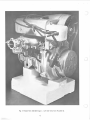
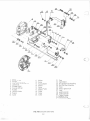
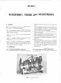
1.3 The Model CCW 340/400/440 engine is shown in
Figure 1 1. One illustration is used, since the three engines
are similar in external appearance. These engines are
designed for use in various snowmobile configurations and
are suitable for use in All Terrain Vehicles or similar
applications.
c
c. Models CCW 440 all models, all versio ns are equ ipped
with Denso ignitions comprised of two low voltage
generating co ils and two high voltage coils all of the
same polarity.
1.4 The instructions deta il the procedures and tools required to ensure efficient operation, servicing and repair of
the engine and component parts. Refer to Parts Catalogue for
tool cross-reference.
Engine nuts, bolts and threads are metric except for the
engine mounting bolts, which are 7/16" SAE coarse, and the
power take off (P.T.O.) end of the crankshaft wh ich is 1/2"
SAE fine (20TPI) .
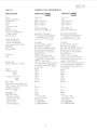
1.8 TECHNICAL DATA
Table 1-1 details specifications applicable to all models of
the CCW 340, 400, 440 eng ines in service at the present
time.
1.5 Carburetion data for the engine models covered in this
manual is detailed under separate instructions. For carburetor technical requ irements refer to Appendix I, or to
app licab le manufactu rer's specifications.
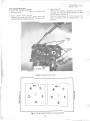
1.9 TOOL REQUIREMENT
The fo llowing is a list of to ols required for the overhaul and
adjustment of models CCW 340, 400 and 440 engines.
1.6 MODEL DESIGNATION
1.7 The letters and numbers in the subject engine models
designate the following: -
a. Special Tools
CCW
Manufacturer's type designation.
Cubic centimeter displacement
340/400/440 - S Manual Start
- E Electric Starter
- G Geared flywhee l (for subseq uent electric
starter installation).
SERIAL NOS.
COMMENCING
c
18
19
25
28
29
35
38
39
. .... .
......
..
..
. . . .. .
.
..... .
b. Standard Tools
MODEL
ccw 400/1
ccw 340/1
ccw 440/1
ccw 400/2
ccw 340/2
ccw 440/2
ccw 400/3
ccw 340/3
Reference
Tool, Flywheel puller Part 43-0790-90
Para. 3.2.1 ( 1)
Tool, Main Spring, Starter Rewind. 43-0797-60
Para. 4.4
Tool, Bearing puller (crankshaft). Part 43-0791-70 Para. 4.8.1
Tool, Flywheel Lock in g. Part 43-0798-40
Para. 3.2.1 (j)
Tool, Fan Pulley Locking. 43-0792-50
Para. 4.2.1(a)
10/13 mm spanner
13/2 1 mm Box spanner and handle
22 mm spanner
22 mm socket wrench and ratchet
Piston ring removal tool
Piston ring compressor
Piston ring groove cleaning tool
Circlip remova l tool
Torque wrench (pounds feet)
Dial indicator
Degree wh eel
For Physical
Differences
See Spec. Sheet
Page 1.4
1-1
Feeler Gauge
Spark plug tap
Spark plug wire gauge
Thread Cleaning tools
Wire brush (spark plugs)
Soft meta l (non ferrous)
Ph illips screw driver set
Common screw drivers
Soft hammer
0
C)
Fig. 1-1 Model KEC 340/400 Engine - Left Side View from Flywheel end.
1-2
CCWTOOLLIST
43-0797-60
REWIND SPRING TOOL
43-0791-70
BEAR ING PU LLER
c
43-0790-90
FLYWHEEL PULLER
43-0798-40
FLYWHEEL LOCK
43-0792-50
FA N LOCK
1-3
REP LACEMENT PAGE
MARCH 1971
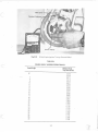
TABLE 1-1
TECHNICAL DATA CCW-340 MODElS
SPECIFICATION
CCW 340 SER. 2900000
2999999
Two stroke
Two
339 cc (20.9 cu.in .}
60 mm (2.36 in.}
60 mm (2.36 in.}
8.5
25 BHP at 5800 rpm
(23 lbs.ft.} at 5250 rp m
Cycle:
Number of cylinders:
Displacement:
Stroke:
Bore:
Compression ratio:
Rating:
Maximum torque:
Specific fuel consumption
under full load:
Ignition system :
Contact breaker gap:
Ignition timing setting
when fully advanced:
(Static timing setting}: BTDC
Spark Plug:
Spark plug gap:
Starter system:
Carburetor:
Fuel:
Mixture ratio:
Rotation direction of engine:
Weight:
Inlet port, timing
height
width
Exhaust port timing
height
width
Piston height:
Piston ring, chromium pl ate, top
Piston ring, gray cast-iron, bottom
Cylinder head, volume
Cooling fan blades
ratio
Magneto, make 340S only
340 GE
IGNIT ION CO ILS (340S}
Resistance, primary
Resistance second ary
Current rating
Spark in free air
(three needle gap}
CCW 340 SER. 3900000
3999999
Two stroke
Two
339 cc (20 9 cu. in.}
60 mm (2.36 in .}
60 mm (2.36 in .}
8.2
28 BHP 6500 rpm
(22.4 lbs.ft} at 6000 rpm
400 gr/ps.h (0.88 lb/ps.h}
Auto-advanced flywheel ign ition
with lighting coi i1 2V-75W
0.3 to 0.4 mm (.012 to .016 in .}
400 gr/ps.h (0.88 lb/ps.h}
Auto-advanced flywhee l ignition
. with lighting coi i12V-75W
~~. 0.3 to 0.4 mm (.012 to .016 in. }
230 BTDC
so (.015" BTDC on Piston}
NGK B 8H or equ iva lent
0.5 to 0.6 mm (0.020 to 0.024 in .}
Rewind starter with emergency
starting pu lley or electric starter
(output 0.5 kw}
Tillotson HR or equ ivalent
Mixture, gasoline of known brand
and special air coo led two stroke
engine oil. (See Table 2-2}
20 : 1 (at normal operating conditions}
Left hand (standard configuration}
see toward the power take off end
of the engine.
60 lbs.
23 mm
42 mm
1680
23 mm
28 mm
67 mm
2 o BTDC
T' o (.023" BTDC on Piston}
NGK B 8H or equivalent
0.5 to 0.6 M.M. (0.020 to 0.024 in.}
Rewind starter with emergency
starting pul ley or electric starter
(output 0.5 kw}
Tillotson HR or equivalent
Mixture, gasoline of known brand
and special air cooled two stroke
engine oil. (See Table 2-2)
20 :1 (at normal operating conditi ons}
Left hand (standard configuration}
see toward the'power take off end
of the engine.
60 lbs.
1540
25 mm
45 mm
1680
23 mm
36 mm
66 mm
1
1
1
1
138°
16.35cc
16.3 cc
10
..
1.81 :1
1.81: 1
Sawafuji
(For Models G & E Kokusan
Kokusan
see Kokusan Data Kokusan
Kokusan
Sawafuji
under CCW 340
1.65 ohms± 10%
.37 ohms ± 15% Ser. 39- }
8.35 K ohms± 15%
5.2 K ohms± 10%
1.75/2.25 amps
1.5/1.75 amps
8 mm @500 RPM
9 mm @500 RPM
15 mm @5,500 RPM
16 mm@ 5,500 RPM
8
'~!~:. ~
- ~
1-4
....
INSERT PAGE
MARCH 1971
-
TABLE 1-1
TECHNICAL DATA CCW-400 MODELS
SPECIFICATION
CCW 400 SER. 2800000
2899999
Two stroke
Two
398 cc (24.3 cu.in )
60 mm (2.36 in.)
65 mm (2.56 in .)
8.5
30 BHP at 5800 rpm
(27.3 lbs.ft.) at 5500 rpm
CCW 400 SER. 3800000
3899999
Two stroke
Two
398 cc (24.3 cu. in.)
60 mm (2.36 in.)
60 mm (2.56 in.)
8.2
33 BHP 6500 rpm
(26.7 lbs.ft) at 6000 rpm
400 gr/ps.h (0.88 lb/ps.h)
Auto-advanced flywheel ignition
with lighting coil 12V-75W
0.3 to 0.4 mm (.012 to .016 in.)
400 gr/ps.h (0.88 lb/ps.h)
Auto-advanced flywheel ignition
with lighting coil 12V-75W
0.3 to 0.4 mm (.012 to .01 6 in.)
230 BTDC
so (.015" BTDC on Piston)
NG K B SH or equivalent
0.5 to 0.6 mm (0.020 to 0.024 in.)
Rewind starter with emergency
starting pulley or electric starter
(output 0.5 kw)
Tillotson HR or equivalent
Mixture, gasoline of known brand
and special air cooled two stroke
engine oil. (See Table 2-2)
20: 1 (at normal operating conditions)
Left hand (standard configuration)
see toward t he power take off end
of the engine.
60 lbs
1380
26 mm
46 mm
1680
23 mm
38 mm
67 mm
230 BTDC
100 (.023" BTDC on Piston)
NGK B 8H or equ ivalent
0.5 to 0.6 M.M. (0.020 to 0.024 in.)
Rewind starter with emergency
starting pu lley or electric starter
(output 0.5 kw)
Tillotson HD or equivalent
Mixture, gasoline of known brand
and special air cooled two stroke
engine oil. (See Table 2-2)
20:1 (at normal operating conditions)
Left hand (standard configuration)
see toward the power take off end
of the engine.
60 lbs.
1460
25 mm
48 mm
1680
23 mm
40 mm
66 mm
1
Cycle:
Number of cyl inders:
0 isplacement:
Stroke:
Bore:
Compression ratio:
Rating:
Maximum torque:
Specific fuel consumption
under full load :
Ignition system:
Contact breaker gap:
Ignition timing setting
when fu lly advanced :
(Static timing setting): BTDC
Spark Plug:
Spark pi ug gap :
Starter system :
Carburetor:
Fuel:
Mixture ratio:
Rotation direction of engine:
Weight:
Inlet port, timing
height
width
Exhaust port, timing
height
width
Piston height:
Piston ring, chromium plate, top
Piston ring, gray cast-iron bottom
Cylinder head, volume
Cooling fan blades
ratio
MAGNETO
IGNITION CO ILS
Resistance, primary
Resistance, secondary
Current rating
Spark in free air
(three needle gap)
1
1
17.0 cc
1
8
10
1.81:1
Kokusan
Kokusan
1.65 ohms± 10%
5.2 Kohms±10%
1.5/1.75 amps
9 mm @500 RPM
16 mm@ 5,500 RPM
2.23:1
Kokusan
Kokusan
1.65 ohms± 10%
5.2 Kohms ± 10%
1.5/1.75 amps
9 mm @500 RPM
16 mm @5,500 RPM
18.2 cc
1-5
INSERT PAGE
MARCH 1971
TABLE 1-1
TECHNICAL DATA CCW-440 MODELS
SPECIFICATION
CCW 440 SER. 2500000
2599999
CCW 440 SE R. 3500000
3599999
Cycle:
Number of cylinders:
0 isplacement:
Stroke :
Bore:
Compression ratio :
Rating:
Maximum torque:
Specific fuel consumptio n
under full load :
Ignition system:
Two stroke
Two
440 cc (26.6 cu.in .)
60 mm (2.36 in.)
6S mm (2.6S in.)
7.S
33 BHP at 6000 rpm
(30.5 lbs.ft.}. at 6000 rpm
Two stroke
Two
440 cc (26.6 cu.in.)
60 mm (2 .36 in.)
6S mm (2.6S in.)
7.S
37 BHP 6500 rpm
(29.6 lbs.ft) at 5750 rpm
400 gr/ps.h (O.SS lb/ps.h)
Auto-advanced flywheel ignition
with lighting coil 12V-75W
0.3 to 0.4 mm (.012 to .016 in.)
400 gr/ps.h (O.SS lb/ps.h)
Auto-advanced flywheel ignition
with lighting coil 12V-75W
0.3 to 0.4 mm (.012 to .016 in.)
230 BTOC
so (.015" BTDC on Piston)
NGK B SH or equivalent
0.5 to 0.6 mm (0.020 to 0.024 in.)
Rewind starter with emergency
starting pulley or electric starter
(output 0.5 kw)
Tillotson HR or equivalent
Mixture, gasoline of known brand
and special air cooled two stroke
engine oil. (See Table 2-2)
20:1 (at normal operating conditions)
Left hand (standard configuration)
see toward the power take off end
of the engine.
60 lbs.
1500
25 mm
46 mm
16S 0
23 mm
41 mm
66 mm
1
1
22.S cc
10
230 BTOC
so (.015" BTOC on Piston)
NGK B SH or equivalent
0.5 to 0.6 M.M. (0.020 to 0.024 in.)
Rewind starter with emergency
starting pulley or electric starter
(output 0.5 kw)
Tillotson HD or equivalent
Mixture, gasoline of known brand
and special air cooled two stroke
engine oil. (See Table 2-2)
20 :1 (at normal operating conditi ons)
Left hand (standard configurati-on)
see toward the power take off end
of the engine.
60 lbs.
1540
26 mm
4S mm
168°
23 mm
43 mm
66 mm
1
1
23.7 cc
10
2.23 : 1
Denso
Oenso
.37 ohms± 10%
S.35 K ohms ± 15%
1.75/2.25 amps
S mm @500 RPM
15 mm @5,500 RPM
Contact breaker gap:
Ignition timing setting
when fully advanced:
(Static timing setting): BTD C
Spark Plug: ·
Spark plug gap:
Starter system :
Carburetor:
Fuel:
Mixture ratio :
Rotation direction of engine:
Weight:
Inlet port, timing
height
width
Exhaust port, timing
height
width
Piston height:
Piston ring, chromium plate, top
Piston ring, gray cast-iron, bottom
Cylinder head, volume
Cooling fan. blades
ratio
MAGNETO
IGNITION COILS
Resistance, primary
Resistance secondary
Current rating
Spark in free air
(three needle gap)
l.SU
Denso
Den so
.37 ohms± 10%
S.35 K ohms± 15%
1.75/2.25 amps
9 mm @500 RPM
15 mm @5,500 RPM
1-6
--
SECTION
n
c
OPERATION AND SERVICE INSTRUCTIONS
1. To induce a mixture of fuel and air into the crankcase
2.1 PRINCIPLES OF OPERATION
c
via the carbureto r.
a. The CCW two stroke engine is designed to complete in one
2. To compress the charge in the combustion chamber.
revolution, or two strokes of the piston, the complete
d. The second stroke of the piston, from T.D.C. to B.D .C.,
cycle of (a) fuel/air induction, (b) compression of the fuel
also has two functions:
mixture, (c) combustion, (d) exhaust of the burned gases.
1. To uncover t he exhaust ports and allow the burned
b. The construction of the engine requires a sealed crankcase
gases to escape.
and a cylinder having four carefully positioned ports as
2. To compress the fuel mixture in the crankcase and
follows:
transfer it th rough the two transfer ducts to the
1. Carburetor inlet for induction of the fuel/a ir mixture.
combustion chamber.
2. Two transfer ducts leading to transfer ports for
transferring the mixture from the crankcase to the
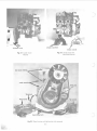
2.2 SEQUENCE OF OPERATION (see Figure 2-1)
combustion chamber.
3. Exhaust port for exhausting the burned gases.
a. As the crankshaft rotates, the piston moves from t he
c. The first stroke of the piston, from bottom dead center
B.D.C. position, thus creating a depression (or partial
(B.D.C.) to the top dead center (T.D .C.), has two
vacuum) in the cra nkcase. When the piston uncovers the
functions :
Fig. 2·1
1\\
COMPRESSION
AND
INDUCTANCE
COMBUSTION
OF
CHARGE
FUEL TRANSFER
2-1
LOOP SCAVENGE
b.
c.
d.
e.
carburetor inlet port, fuel/air mixture, metered by the
carburetor, is admitted to the crankcase.
Continued upward movement of the piston will compress
the charge in the combustion chamber until, at a point
near T.O.C., the spark from the spark plug will ignite the
mixture.
Resultant expansion of the ignited fuel will push the
piston toward· B.D.C. Moving downward, the piston first
uncovers the exhaust port and allows the hot gases, still
under considerable pressure, to escape to atmosphere
through the exhaust system.
Continuing downward, the piston will now uncover the
two transfer ports and close the carburetor inlet port. The
mixture in the crankcase and lower part of th8 cylinder is
displaced by the piston and conducted through the
transfer ducts to the combustion chamber above the
piston. The fresh charge, entering through the two
transfer ports will form a loop (see Figure 2-1 0). thus
scavenging the cylinder of burned gases.
The cycle will repeat continuously as from paragraph (a)
until the engine ignition is switched off.
2.3 IGNITION SYSTEM
2.3.1 General
The ignition system used with model CCW 340 and CCW 400
engines is basically the same as systems used with most
conventional two stroke engines. It consists of a low tension
magneto, two high tension ignition coils, two ignition spark
plugs, spark plug (high tension) lead wires, an ignition switch
and the required electrical wiring.
Modei340S engines differ from 340E, 340G, and 400 engines
in magneto design. Magnetos in use on the model 340S
incorporate only one low tension generating coil. All other
models covered in this manual use two low tension generating
coils. Refer to paragraphs 2.4.2.1 and 2.4.2.2.
sets are grounded to the magneto f rame through a common
ground.
2.3.2.2 Kokusan Ignition (See Figure 2-3)
The magneto used with model 340E, 340G and 400
( KO KUSAN) ignition systems has two low tension generat ing
coils. 0 ne end of each coil is grounded to the magneto frame.
The other end of the coil connects in parallel to the brea ker
point set and the primary of one ignition coil.
2.3.3 Operation (See Figures 2-2 and 2-3)
The ignition switch is connected in parallel with the primary
windings of the ignition coils. Operation of the ignit ion
switch to the "RUN" position, opens a circuit between the
windings and allows the contact breaker points to control the
ignition circuit.
The flywheel incorporates four permanent magnets and a
breaker point cam and auto advance mechanism. In operation, as the flywheel rotates, an electrical current is generated
in the low tension generating coil. The rotating breaker point
cam activates the breaker points, opening and closing them in
accordance with a timed ignition sequence. (Refer to Section
V, paragraph 5.4.4). Closing the points causes the buildup of
a magnetic field in the ignition coils. Opening the points
causes a very rapid collapse of the field, thus inducing a high
voltage current in the secondary windings of the coil. High
tension spark plug wires conduct the high voltage current to
the spark plugs.
Self induced high voltage current in the primaries is momentarily stored in the condensers to prevent arcing across the
point contacts. When the contacts next close, the condensers
will discharge back to the ignition coils, thus assisting in the
buildup of the magnetic field in the coils.
The ignition circuit will continue to function until the
ignition switch is turned to the "OFF" position which will
maintain a circuit and prevent ignition.
2.4 DETONATION:The internal combustion engine is designed to induce a
combustable mixture of gasoline and air into the cylinder
which is subsequently ignited by a spark plug, and the
resultant gas expansion utilized to produce the power stroke.
Some considerable care is taken in the design to ensure that
the combustion takes place at a controlled rate, but under
certain conditions the charge will burn at a highly excessivE!
rate, producing abnormal gas temperatures and pressures in
the cylinder. This condition is called detonation and may,
therefore, be defined as the rapid and uncontrolled burning
of the charge which commences at th e point of ignition by the
spark plug and is completed prematurely over a very short
movement of the piston.
2.3.2 Description
The magneto assembly is mounted to the engine crankcase at
the flywheel end. It functions to generate low tension
impulses in the primaries of the ignition coils. Two sets of
contact breaker points, one set for each cylinder, are installed
in the magneto. During engine operation, a cam, mounted on
the flywheel, opens and closes the breaker points in sequence.
A condenser, wired in parallel across each set of breaker
points, protects the points from damage caused by selfinducted electrical surges in the primary coil. Lighting and
battery charging coils (see paragraph 2.5) are mounted on the
magneto coil plate. The coils produce the electrical power
required to operate a 12-volt lighting system and to charge
the battery used with electric started engines.
Low tension (primary wires) leading from the magneto are
encased in a protective cover and routed through a grommet
located in the fan cover case, to the ignition coupler on the
fan cover.
2.4.1 The causes of detonation are many and varied, but all
have the common effect of overheating the charge towards
the spontaneous combustion temperature of the fuel. Consequently, when the charge is further heated by compression
and ignited by the spark, the flame spread rate is very rapid
indeed, resulting in the formation of the high pressure wave
which impinges on the combustion chamber surfaces to
create the sound of detonation of "pinging" which is so
familiar to many people.
2.3.2.1 Sawafuji Ignition (See Figure 2-2)
The magneto used with model 340S (SAWAFUJI) ignition
systems has one low tension generating coil. Each end of the
coil is connected in parallel to the primary of one ignition coil
and one breaker point set. The condensers and breaker point
2.4.2 It cannot be emphasized too strongly that if detonation is allowed to persist, serious damage may resu It to the
2-2
)
INS ERT PAGE
MARCH 1971
2.3.2.3 Denso Ignition
2.5.2.4 Denso lighting System for CCW 440
This magneto is used on all models of the CCW 440 engine.
It is functionally similar to the Kokusan ignition descri bed
in 2.3.2.2. and the Kokusan Schematic at the bottom of
page 2·3. appl ies equally to the Denso Ignition System.
All CCW 440 Engines are equ ipped with six terminal
ignition co uplers similar to later models of the other'
engines (See 2 5.2 2). Typical lighting circu it curves for the
Denso Ignition System are incl uded on· insert page 2-10
A-C.
2-2A
J
-,
SPARK PLUG
j_
c
I
I
POINT
SET
I
I
L. T.
COIL
I
!
I
POINT
SET
IGNITION
COIL
WHITE
WHITE
Fig. 2-2
SAWAF UJI MAGNETO
340S ONL y
TO
-IGNITION
-SWITCH
1
1
L~
6or8 POLE
GNITION
COIL
c
L.T.
COIL
POINT
SET
CONDENSER
,- -1
,,
I
I GNITION
COIL
I
_'J' O
IGNITION
1-sWITCH
"o ' - - - - -
L. T .
COIL
c
POINT
SET
ONDENSEf
I
I)
/
/
Fig. 2-3
KOKUSAN MAGNETO
340G-E
400 S-G-E
I
WHITE
~ER~2-3
6or8 POLE
I GNITION
COIL
blue in colour. Both of these wires are routed to the
ignition coupler.
The lighting coil winding is yellow in colour. One end is
routed to the ignition coupler and the other is grounded at
the magneto.
engine. Overheating of the engine can cause distortion of the
cylinder and cylinder head, seizing and burning of pistons,
breaking of cylinder flanges and studs etc.,
In addition, prolonged detonation may lead into pre-ignition
of the charge and even more serious consequences to the
engine. It is essential, therefore, that detonation should be
recognized and the cause el iminated as soon as possible.
A headlamp and tail lamp with maximum rating of 35
watts may be installed on the vehicle. The wire to operate
the light switch is connected to the yellow terminal in the
ignition coupler.
2.4.3 Most of the common causes of detonation can be
easily rectified: 1. High compression pressures. (CCW 340/400 = 175-180
PSI. cold at 500 RPM.)
2. Incandescent points in the combustion chamber due to
ash deposits.
3. Wrong type of spark plugs. (See Table 1-1)
4. Spark plug overheated due to seat washer being worn or
missing.
5. Incorrect ignition timing. (See section 5.4.4)
6. Weak carburetor settings.
7. High ambient temperatures. (Over 950 F.)
8. Partially choked exhaust system causing high back pressure.
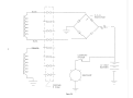
MANUAL STARTED ENGINES (See Figure2-6)Twinhead
and tail lamps( 12 V. 35W - 12 V. 3W) .
See drawing Number E 340S-150. Two 12 volt, 35 watt
head lamps are connected in serieswith the single yellow w.ire.
Three 12 volt, 3 watt tail (or speedometer) lights complete
the circuit in aseries parallel connection with a ballast resistor
rated 7 ohms, 40 watts. A parallel circuit with a single pole
double throw switch is shown connected across the headlamps. In the event of a lamp failure, the switch can be placed
in left or right position to provide a circuit to the remaining
head and tail lamps.
N.B.-This circuit can be omitted if not required.
Materials required:-Load resister 7 ohms. 40 watts
SPOT Switch. 5 amps.
These items are available from Canadian Curtiss-Wright,
Limited.
2.4.4 PRE-IGNITION may be defined as the premature
burning of the charge due to spontaneous combustion, and
before the specified timed ignition point by the spark plug.
The resultant gas expansion, acting on the rising piston, generates extreme temperatures and pressures in the combustion
chamber and frequently results in broken pistons, bent
connecting rods, twisted or bent crankshaft and damaged
bearings.
Pre-ignition is usually caused by overheating and can be
readily identified by the very heavy knocking which is due to
gas expansion on the rising piston. It is usually preceded by
detonation, but certain conditions such as an under-sized or
choked exhaust system. will cause the engine to go straight
into pre-ignition without detonation. It is imperative that the
engine should be stopped at once by closing off the air supply
to the carburetor. It will be apparent that the engine cannot
be stopped by switching off the ignition.
ELECTRIC STARTED ENGINES. (See Figure2-5)
b. On engines equipped with an electric starter. the two blue
wires at the ignition coupler are plugged into a C.C.W.
rectifier, part number 43-0710-00, and the AC is converted to DC (direct current). The black wire is grounded.
From the rectifier, DC is routed through a 7.5 ampere fuse
to the battery. Power to operate the lights is taken from
the battery.
2.5.2.2 Engines with Serial Numbers Modei340-G-F
2903614, Modei400-S-G-E 2809570 and Subsequent
a. Engines bearing serial numbers as above are equipped with
a six pole terminal coupling for the ignition and lighting
circuits. In addition, the separate lighting and battery
charging coils as per paragraph 2.5.2.1 have been changed
to a single center tapped coil. The ends have been
terminated in two yellow wires and the internally center
tapped ground connection has been extended by a brown
wire to the terminal block.
2.5 LIGHTING SYSTEM
2.5.1 Vehicle Iighting is provided by lighting and battery
charging coils in the magneto, and the necessary wiring and
light switches required to operate the system.
2.5.2 Operation
N.B.
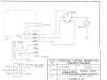
2.5.2.1 Engines Previous to Serial Numbers:Model 340-2903614, Model 400-2809570. Typical vehicle
lighting circuit, See Figure 2-11.
Engines bearing serial numbers previous to 340-2903614 or
400-2809570 are equipped with an eight terminal ignition
coupler. The lighting and battery charging circuits include
two separate coil windings which produce 75 watts AC
(alternating current) during magneto operation. 0 ne coil
winding supplies the power required to operate the lighting
system and the other winding supplies the power required to
charge a 12 volt battery for use with electric started engines.
This brown wire may be disconnected provided a satisfactory
ground is maintained between the lighting circuits and the
engine.
The coil is rated at a nominal 12 volt 75 watt maximum and
can be connected to meet the various electrical configurations.
1. ONE HEADLAMP 12 V35W-ONETAIL LAMP 12V3W
See Figure2-7
A ballast resistor rated at 5.3 ohms 40 watts must be
connected in parallel with the head lamp to prevent lamp burn
out. It will be noted from Figure 2-7 that an alternative
resistor at 7 ohms 40 watts will raise the operating voltage
across the lamp to give a better light at the cost of reduced
lamp life.
MANUAL START ED ENGINES (See Figure 2-4) Single head
and tail lamp ( 12 V. 35 W-12 V. 3 W)
a. The two wires from the battery charging coil winding are
2-4
0
I
I
~
c
I
I
~
I
.I
~
I
I
Fig. 2·4
340 S-G
400 S-G
-+C><}+-
~
~ _j
CO UPLER
8 POLE
c
I
1
I
I
I
I
-,c><:>-r
-p-~
Fig. 2-5
340 E
400 E
jC><:::}r
~
lovf'l..ER
8 POLe
2-5
H£AOlAt'\f'
I
I
I
I
A
c.c.w.
RECTIFIER
~
I
I
I
I
I
~
BLUE
N
c:n
I
;(,t:j.J.i.I.I!.:!W
I
I
I
I~
I
I
~
I
I
~
I
I
I
c )HEADLA~
1
I
~
~ ~OUPLER
12 VOLT
BATTERY
I
8 POLE
Figure 2-6
l)
v
u
c
2. Two Headlamps 12V35W- Two Tail Lamps 12V3W
(See Figu re 2-8)
The head and tail lamps are connected in parallel across one
yellow wire and ground through the lighting switch, and the
ballast resistor is, of course, unnecessary.
intervals as necessary. (See Section Ill, para. 3.3.4) . Discard
excessively burnt or damaged plugs. Install on ly specified
spark pi ugs after adjusting to proper gap. (Table 1-1).
2.6.2 Fan Belt
Periodically check fan belt for wear, fray ing and proper
tension. A properly adjusted fan belt sho ul d leave approximately 1/4 inch side play when flexed by hand at a point near
center of belt length.
Adjust fa n belt tension as follows:
a. R-emove 19 mm nut, lockwasher and plain washer from
threaded end of fan shaft, using locking tool Part No.
43-0792-50.
b. Remove outer pulley. Remove spacer(s) , as required, to
achieve proper tension.
c. Install outer pulley, plain washer, lockwasher and nut.
Ensure belt is properly engaged between pulley halves.
Tighten nut securely.
NOTE : Retain surplus spacer(s) for use when a new belt is to
be installed.
3. Electrical Start Engines (See Figure 2-9)
On engines equipped with an electric starter motor, a full
wave rectifier, CCW Part No. 43-0715-10, is connected to the
two yellow wi res at the terminal coupler and the A. C. output
is converted to D.C. 7.5 amp fuse is connected to the D.C.
output red wire and the circuit is completed via the lighting
switch to charge the battery. Head and tail lamps are
connected across the battery terminals as shown in Figure
2-9.
2.5.2.3 Model 340S only. Engines with serial numbers
2903614 & subsequent. See fig. 2-12.
Engines bearing serial numbers as above are equipped with
Sawafuji magnetos & six pole connectors for lighting &
ignition circuits. The separate lighting and battery charging
coil, have been retained as per paragraph 2.5.2.1.
2.6.3 Troubleshooting
Table 2-1 lists probable causes of engine malfunction and
remedial action required to correct faults. For spark plug,
breaker points and engine timing specifications, refer to
Technical Information, Tab le 1-1.
2.6 PERIODIC SERVICING
2.6.1 Spark Plugs
Remove, inspect, clean and/or adjust spark plugs at regular
c
c
2-7
'
!
•
!...
'-· ~
. '-r.::·
.
·-
L
. H-i . ' ' . ~ - i,, r.. ·"-}'l!:T.il'll.l-r'l.!- p.;o
11" ~ '!~
......
.... t-v~-~•v-:·
- ,.,.
. .·
.!
. "
rr· .
[.P.
-) :I'
:)
''
''
,,
~
c...,
~
'+-
··0. t-'--
-!
''
!"!.~. . :""'
''
''
' '
tr
• ''
,- -\~-
..
'--o-t: ,.,_.,_
~"--''
~ :.
,·
MAO~
IN CAHAOA
2-8
10 x 10 TO THE V2 INCH
GS-12
c
f-1-f++l '
._
1-,-=
....!..
·IJ· l- -"\h-'t-
c
ta
c
I§ MICRO(QRAPH
MAD£ IN CANADA
2-9
10 x 10 TO THE V2 INCH
GB-12
..
:-h
- -,.... .
!I'I---
_~
.., __
.....
~
-~+~'+
bt-'
I!
MAOI!: IN CANADA
2-10
.
- .~
I
•
I "
10 x tO TO THE V2 INCH
GB-12
ccw
V
440
Hmt-· -:[ ·
1-r-
I 6 -fit
·-+-+--+=:-+ - j_
i- +~---t--+
+- -
I
-~
--
. ,_ -H-l-1- - · -
VOLT:S
15
--t-
-
t--
-+1·
+
- -
t
t-t-
Lf- •- ,_ - - - - -
-
-t-
l'f-j-t-
t-
_J_
~·-+-:- =t _tj~· -
l--+--+---1-+---1-
- -
-r- - --
I
1...
.
-H
t~t-j-+--t---IA-it-t---+---t+++---¥"-+--1-H-1-++-+-++-++++++++-+---t+--t-+t--1
..:. -- -
-
. -· v
I-'
-¥H-+++~~+~~+~~~-rH~t++++--1+i--1
-l---++-+-LW -_ : ~
i-
t
-1--+ I I I I I I I I I I I 1--l--l--+-l--t+-l--lI I I I I I I I I I I I I I I I I I I I
II
•- ..LL
r-- ---L!
R= 5.3D
~~~
~.-
~r ~--
U-+--+-+--+---H---+--+-+-H-++-+-t-+-+---1-1---+-·+--+--+++-+-hl11
12
_
+
-
-
i----+-
.
-
· --t - ·
--:_
t-
+ '- -
:
- -~
- -
--
++t
-
-
:= ±... ~~ - R--- --
t;...l
)
CENTRE TAP LIGHTING COIL
DENSO IGNITION
R-=to.to5"n
~~t-tt_ :ji-t~-l -i±- ·_ .-~-+fi ~-- :-__:H~ -t _.1j- -- - ~L
- -~ . - r-- - :~ ~ .... ~~ -_ -: ~t~
17
/3
(
()
( )
§
-
1
v
T
. :tu
· ·
-++
- ~-
+r--+- : ~-il± Jtli±±i±±i]±t±±+ I I I I I I I I I I I I I I I I I I t_
- _
'jj+lt
NoTE: 5 WITCH IS 7
OMITTED
TO
SIMPLIFY CIRCUIT,
C)
)>
17117
/0
q
0
20
10
s-o
~0
30
RPM
X
~0
70
/00
{,.;;
Lf ~
~
111 111111 mTIIII II II I I II II I l l l lll lllll l lll lll lll l lll I I I I II I I I I I I I I I I I
s::;z
)>(/)
m
n :IJ
:IJ
3
~ I
0
I
I I I I I i I I ! I I I i I I I I 1 f 1 I I I I II I I
/0
20
I'I
30
I I I I I
I I
~
I I I I I I I I I I I I I I I I I I I I I
"10
RPM x !00
50
~0
I
I I I I
I
I~
I I,
70
~
--o
CD)>
-..J G)
Fig. 2-9A
~ m
~~
c:r:&l
ccw 440
CENTRE TAP LIGHTING COIL
DENSO IGNITION
a..~
I-I
a:u
wa:
~~V
n
)
(}
-'ffi''~''#''m''1~
' '~
''rn'''~''~"m'''U"U''ill'~'TI''IT"rn'''~''~
' 'm'''~''~''~~~~~~~~~~~~~~~~~~~~~~,,~,~-~~·
I if-F}-+-+ I I I I I I I II I I I I I I I I I I I I I I I I I I I I I I I I I I I I I I I I I I I I I I I I I r l 11Q.:H11li1TTT
VOLTS
till~
/$
;p
J.,.
13
-1 11 i IIII III IIII.IIIII I IIIIIIIII I IIIIII III I IIIIIJJ+H11111111111111111111
12
I II II I II I Ill I I I II I I Ill II I II I II II I I I II I IJ11 II I I I I II I II II II I II II I I I I I I I I i
II
-IIIIIIIIII II IIIIIIII IIIIIIIIII IIJ#lllll llllllllll llllllllll lll lll ittH
I o-I I I I I I I I I I I I I I I I I I I I I I I I I I l%1I I I I I I I I I I I I I I I I I I I I I I I I I I I I I I I I I I I I I I I 1 1 1
17
9
CD
D
0
-~ 111111111 1 111111111 1 U4 llllffillTilTIII IIII IIIIIIIIIIIIIIIIIIIIIIIIII ~ Non :
e-rrrnlT1Trm=RlTl
. . Y+II IIIIIIII I IIIIIIIII II IIIIIIIIIIIIIIIIIII II IIIIIIII
.ZO
30
itO
RPM
b
. I ,
t---t l
I
_ 1
A
I i
i !
5
'
A11PS
'1 -
i .
i
i
I
0
!00
70
.-
....
'
I
l
I
'
;
H- h-++:
.3
K
hO
I
I
I
~-
.
;
;
...--
5"0
-ri;
1
I...
I
l
I
I
-'-f-H
/0
l
l
I
zo
30
RPM
'10
K
/00
50
00
r
70
SwITCH IS
_
"-'
0/'fJTTcD
TO
.
SI/'1PLIFY
CIRCUIT.
ccw
15
VOLTS
440
CENTRE TAP LIGHTING COIL
DENSO IGNITION
INSE RT PAG E
MARCH 1971
U! lllllltn IIIIIIIUIIIIIIIIIIIIIIIIIII tlllllll ll llllllll ll lllllll llli
l't+++l- I I I I I++++ I I I I I I I I I I I I I I::U--HTI I I I I I I I I I I I I I I I I I I I I I I I I I I I I I I I I I I I I I I
F'
13
I I I I I
!111
f
+=FH=J
I II II I ll 111 11 11 111 111 1111 11 111111111111 I l l 111 1 1 11 II I II I I
12 +t-++++i I I I !+++++++++++ I I I I I I I I I I I I I I I I I I I I I I I I I I I +++ I I I I I I I I I I I I I I I I I I I
11 111111111111111111111ttMt 1111 11111111 11 11 111111111111111111 1
!J I I I I I I I I
NoTE : 5 wITCH
-•
IS
0/VIITTE{) TO
SIMPLIFY
CIRCtJ/T.
I I I I I I I I I I I I I I I I I I I I I I I I I I I I I I II I I I I I I I II I I I I I I I I I I I I I I I I I I I I I I I I I I I I I I
10
u
0
9
~l I I I I I
l
I'
/0
I I
0
I I I I I
LJ
I ~ I I I I I I I I I
20
I'
I I I I I I I I
30
RPM
A
K
I'
I I I I I I I I
II
I I I
11111-1
I J.J..II I I II~
tfO
100
5"0
bO
70
'-10
50
~0
70
N
-
3
2-
AMPS
....
0
""
-2
-3
~
""
....
I
0
10
2.0
30
RPN
K
/00
\._
l
(~
-,
TO
I
POINTS
TO
ICrN lTION
COILS
I
I
HE"'OLJ\MP
C HA.?-61Nu
~_r
COIL
li6HrHJGCOIL
_.f...NG\NL
·· COU PLE.R
2 RED
J
COUPLE I~
V/£W FROt"\. R&COIL
STA.RnR £NO
TOLERANCES
EXCEPT AS
NOTED
CANADIAN CURTISS- WRIGHT LTD.
TORONTO ONTARIO
DECIMAL
.j..
BLUE
c.cw. E.NGlN E
FRACTIONAL
+
...
DATE
I
I
MI\NUAL
TITLE
TYPICAL
ANGULAR
DRAWN BY
SCALE
I
Nov.2. ~~~o I
8 Po"e
APPROVED BY
s T~RT
WI~ING DI~G-RAI-'\
DRAWING NUMBER
3 40 $.G-.
FIGURE 2 -I 0
4 oo s. G-.
~-··-
1
I
I
I
I
I
- - - - _j
\o
'TO POINTS
IG-NI'tiON
C.OI\.~
!OINIH.H
I
I
HE~t>LIIIM?
~
CHAR<11NGC.Oil
N
1- - - - - - - - -,
1~-,
..----=------,
I
I
I
lluHTINu
C. 0 I L
I
I
I
, ___ _ _ _ _ _ _ _ _ j
43 ·0710-00
COUPLER
__
I
Et:ifrlb1 E
CD\J PLER
2 RED
Vlt'W rr<-o~ Rtc..b\L
STI\RicR t:NtJ
TOLERANCES
EXCEPT AS
NOTED
3
4
FRACTIONAL
YEUOV/5
6 BLUE
8WHITE
CANADIAN CURTISS- WRIGHT LTD.
TORONTO ONTARIO
DECIMAL
~
BLUE
l
C . C w. R. H. T I F E R
~
<
\NHITE.
-=- lc VOLT
-=- BAT IE R'Y
FU~E
+
ANGULAR
....
SCALE
C.C.'W.
TITLE
DATE
E~<HNE'
DRAWN BY
APPROVED BY
ELEC. TR\t sTART
PI CAL
POLE WIRINCr DIAGRAM
DRAWING NUMBER
3 4-0 E. .
Nov.2.1'\lo
I
8
fiGURE 2-J J
4-00 £.
)
)
-I
To I C:,NiriONCOILS
~--------~----
HfADI.A.MP
I
'TO
POINTS
~r
w
l\G~T I NG
COIL
CHARGING
COIL
L'------E-fi~_...-INE
__
j
COV?L£R
VIEW FACING
BLUE I
YFLLOW
R£DS~:>I
Ct\RBUREIOR
TOLERANCES
EXCEPT AS
NOTED
CANADIAN CURTISS- WRIGHT LTD.
TORONTO ONTARIO
DECIMAL
...
C.t.W'. ENGINe
FRACTIONAL
ANGULAR
APPROVED BY
M.ANU~l
....
.
DRAWN BY
SCALE
DATE
~Jov 1~ .1 no I
DRAWING NUMBER
3 40
Fl&URE
2-12
s.
START
A
0 Nl '(
- ·1
TO IGN\iiON
~T -1
.j
COIL~
TO
PO\NT5
-
,.
I
I
I
LIG.HTIN& ANO
C HAA~ING COli...
COVPLEP.
___E_1l§ I NE- -
I
TOLERANCES
EXCEPT AS
NOTED
COUPLER
YE.LL OW/------""'
2 YELLO\N
\JlEW FACINCJ
CARBUI\ETOFt
DECIMAL
...
RED 5
TYPiCAL
ANGULAR
...
TRANSTEX Ill 1100-11-87
APPROVED BY
M/\NUAL START
TITLE
+
')
RU
DRAWN BY
SCALE
C.C. W. Ehl GIN E
FRACTIONAL
3--~
CANADIAN CURTISS -WRIGHT LTD.
TORONTO ONTARIO
6 POLE
I
DATE
f\1 0 v 2 I q10 I
°
\VlRlWG-
DlAGM~
DRAWING NUMBER
3'40 G-
F l G- uR E 2 - l 2. A
4I
--
s. G-.
)
\
.
----
II
t
S.OLENOIO
SWIT'>i
:- -
-l
,--------
I
r '
I
I
I
~------------1
TO I C:tN l'l'ION C.OII.'il
HE~OL~M~
,:]__-=
_'__,-
CJl
TO
POl NTS
I
I
LIGHTI~G AND
( I·H~P.uiNCJ C.OI L
,- - - - - - - - - - - -,
I
f•~ I
~
I
~·
I
l
I
I
____f}JG-It{g __ .
J
( CW. fl..E( TIFE R
# 4-3·07i5-IO
COUPLER
TOLERANCES
EXCEPT AS
NOTED
~IJPLER
Y E. L L0 V.J J ----LJ--..J
VIEW EAC~
U~RBUBETOB
Rt. D 5--+e:::::>1
Knn-t1-A'7
C.C.W. EN&l~E
TITLE
T'(P\CAl
ANGULAR
DRAWN BY
SCALE
+
+
ta
CANADIAN CURTISS- WRIGHT LTD.
TORONTO ONTARIO
DECIMAL
.j..
FRACTIONAL
3--+<:::::>~
TQ.&NQTr:'Y
BATTEf\'1
~-----------
I
nit
12-VC\.T
DATE
N~\J. 2. 1'\lo
APPROVED BY
ELEC.TR\C
6 PoL£
WlRlNG-
ST~RT
C\~GR~lA.
DRAWING NUMBER
FlGURE
c-1~
340E.
400 E..
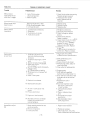
TABLE 2-1
TROUBLE SHOOTING CHART
Trouble
Probable Cause
Remedy
Manual starter
rope comes out but
pawls don't engage.
1. Lack of friction plate
1. Check friction plate returnspring.
return spring action.
2. Defective pawls.
Replace spring as required.
2. Check for broken or bent
pawls. Replace pawls as
required.
Manual starter rope
doesn't return.
1. Recoil spring broken or bent.
2. Pulley housing warped or bent.
3. Starting pulley worn.
1. Replace spring.
2. Replace housing.
3. Replace pulley.
Electric starter
inoperative
1. Loose electrical connections.
2. Poor ground
3. Faulty battery or circuits.
4. Faulty electric starter
1. Retighten connections.
2. Secure ground connection.
3. Check, recharge or replace
battery.
4. Check starter solenoid.
Repair or replace.
5. Inspect starter motor for evidence
of moisture and broken or worn
brushes. Dry out as necessary.
Replace brushes as required.
6. Check starter switch. Replace
if required.
7. Check harness or connector for
bra ken wire. Repair or replace.
Hard to start
or won't start
1. Carburetor adjustments too
lean (not allowing enough gas
to engine).
2. Inoperative diaphragm orflapper
valve.
3. Engine not being choked to start.
4. Spark plugs improperly gapped,
dirty or broken.
5. Magneto breaker points improperly
gapped or dirty.
6. Head gasket blown or leaking
7. Empty gas tank or improper fuel
mixture.
8. Water in fuel system
1. Adjust carburetor. Refer
to Manufacturer's Specifications.
9. Weak coil or condenser
10. Obstructed fuel system
11. Air leak in crankcase or inlet
system .
12. Primarywirebroken.
13. Engine not timed properly.
14. Secondary wire not connected
or spark plug protector not
installed properly.
Impossible to adjust
idle
1. Spark retarding mechanism not
working properly.
2. Pistonsor ringsworn.
3. Faulty carburetor
2· 16
2. Refer to Manufacturer's
Specifications.
3. Ensure choke is fully closed.
4. Remove plugs. Clean, adjust or
install new plugs.
5. Clean, adjust or replace points.
6. Replace gasket
7. Refill tank with specified
fuel/oil mixture (See Table 1-1 ).
8. Drain fuel from carburetor. Add
carburetor de-icer as required
to fuel.
9. Replace faulty coil or
condenser
10. Disconnectfuellines-clear
obstruction. Flush system.
Connect fuel lines.
11. Check crankcase pressure
Table 3-1.
12. Repair or replace primary
w1re.
13. Re-time engine to proper
specifications.
14. Secure secondary wire or
spark plug protector.
1. Repair retard mechanism
2. Replace as necessary.
3. Check carburetor, check valve.
Refer to Manufacturer's Specifications.
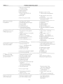
TABLE 2.1
c
Missing at low speed
or won't idle smooth ly
or slowly
Missing at high speed
or intermittent spark.
Coughs, sp its, slows
down, surges
c
TROUBLE SHOOTING CHART
1. Incorrect carbu retor idle
adjustment.
2. Spark plugs improperly gapped
or dirty.
3. Head gasket blown or leaking
4. Loose or broken magneto wires
5 Magneto breaker points
improperly gapped or dirty.
6 Weak coil or condenser
7. Improper fuel mixture
( 1) Too much oil
(2) Too little oil
8. Leaking crankshaft seal
1. Ad just idle- Refer to
Manufacturer's Specifications.
2. Clean, adjust or install
new plugs.
3. Rep lace gasket.
4. Repair or replace wires.
5. Adj ust, clean or install
new points.
6. Replace coil or condenser
7. Refuel, using specified
fuel/oil mixture (See Table 1-1).
1. Spark plugs improperly gapped
or dirty
2. Loose or broken magneto wires.
3. !Magneto breaker points improperly
gap 1.ed or dirty.
4. Weak coli or co ndenser
5. Heat range of spark plug
mco rrect.
6. Leak1ng head gasket.
7. Engine improperly timed .
1. Clean, adjust or install new
plugs.
2. Repair or replace wires.
3. Clean, adjust or install
new points.
4. Replace coil or condenser
5. Install specified spark plugs.
1.1 dleorhighspeedjets
too lean.
2. Leaking gasket flange.
3. Inlet control lever set
too low
4. Pulsalion line obstructed
5 Fuel pump not supplying enough
fue l due to :
( 1) Punc tured diaphragm
(2) Inoperativei lapper valve.
6. Crankca ~e not properly sealed.
7. Idle or ma1n carburetor nozzle
obstructed.
8. Fuel line obstructed.
1 to 5.
Ad just carbu retor or fuel pump.
Refer to Manufacturer's Spec ifications.
9. Carburetor inlet needle and
seat obstructed.
10. Welch plug leaking.
Overheating
1. Carbu 1eto r too lean
2 Carburetor too rich
3 lncor1ect fming
4. Too much carbon
5. Spark plug too hot
6 Air deflector not 1nstalled
7. A1r leak in manifold
8. Crankcasesealleaking
Vibrates excessively or
runs rough and smokes.
1. Idle or high speed ca rburetor
ad justment to o rich.
2. Choke not opening properly
(bent linkage).
2-17
8. Replace seal.
6. Replace head gasket.
7. Re-time engine.
!'
6. Reseal crankcase.
7. Refer to Manufacturer's
Specifications.
8. Remove fuel line. Cl ear
obstruct ion. Replace line.
9. Refer to Manufacturer's
Specifications.
10. Refer to Manufacturer's
Specifications.
1. & 2. Adjust carburetor.
Refer to Manufacturer's
Specifications.
3. Retime engine to Specifications.
4. Remove cyl inder heads. Clean
to p of pistons and inside
comp ression cha mber. Clean out
exhaust port.
5. Insta ll specified spark plugs.
6. Install air deflector.
7. Tighten nuts or change gaskets.
8. Fit new seal.
1. to 5. Adjust carburetor. Refer
to Manufacturer's Specifications.
TABLE 2.1
, TROUBLE SHOOTIN G CHART
3. Inlet control lever too high
(carburetor floods) .
4. Idle 9i r bleed plugged .
5. Welch plug loose.
6. Muffler obstructed
7. Eng ine not secured tightly to
engine support.
8. Water in gas.
9. Water in the ignition switch .
Won't start. kicks back
-,.:::>.~nd backfires.
No acceleration, low top
R.P.M., hard to start
Good spark but engine
runs on one cylinder.
1. Spark plug wires reversed
Flywheel key missing or sheared
Fau lty condenser
Improper timing
Faulty breaker points
6. Unhooked spark retarding
mechanism-or spring broken
2.
3.
4.
5.
1. Spark plugs improperly gapped
or dirty.
2. Magneto breaker points improperly
gapped or dirty.
3. Faulty coil or condenser.
4. Loose or broken magneto wires.
5. Blown head gasket.
6. Inlet lever adjustment too low
8. Add carburetor de-icer fluid
as required.
9. Dry out switch, using suitable
de-icer spray or heat.
1.. Install wire correctly.
2." Replace key.
3. Replace condenser
4. Re-time engi ne
5. Adjust or replace points.
6. Reconnect mechanism or replace
spring
1. Clean, adjust or install new
plugs.
2. Clean , adjust or install new
7. Crankcase leaking
1. Leaking cylinder head
1. Check head fo r warps, cracks.
2. Magneto wires broken inside
(coil ground broken) .
3. Cracked cylinder wall
4. Defective spark plug.
2 Repair or replace wires.
Install new gasket and cylinder head
3. Replace faulty cylinder.
4. Clean. adjust or install
6. Crankcasesealleak ing.
new plug
5. Re-adjust po ints.
6.1nstallnewseal
1. High speed needle set to o lean.
1. to 7.
2. Dirt behind needle and seat.
3. High speed jet obstructed .
· 4. Inlet lever set too low.
5. Choke partly closed.
6. Silencer obstructed.
7. Fuel pump not supplying enough
fuel due to:
( 1) Punctured diaphragm
(2) Fl apper valves distorted.
8. Fuel line obstructed .
9. Not enough oil in gas.
10. Breaker points improperly
gapped or dirty.
11. Engine improperl-y timed.
Engine runs by using
choke at high speed .
6. Check and clea r muffler.
7. Tighten engine mounting bolts.
points.
3. Replace con or condenser.
4. Repair or replace magneto wires.
5. Replace head gasket.
6. Refer to carburetor manufacturer
Specifications.
7.1nstallnewseal.
5. Breaker points improperly gapped
No acceleration. Id les
well but dies down when
put to full throttle.
J
1. High speed needle set too lean.
2. Dirt behind needle and seat.
2-18
Adjust carburetor. Refer to
Manufacturer'sSpecifications
8. Remove fuel line. Clear
obstruction. Repl ace line.
9. Refuel, using specified
fuel/oil mixture.
10. Ad just, clean or install new
points.
11 . Re-time engine to specificatio ns
1. & 2. Ad just ca rbureto r.
Refer to Manufacturer's
Spec ifications.
)
TABLE 2.1
c
TR OU BLE SHOOTING CHART
3. Fuel line obstructed
3. Remove line, clear obstruction,
replace line.
4. Refer to Manufacturer's Specifications
4. Inoperative fue l pump
No power under heavy
load
1. Magneto breaker points improperly
gapped or dirty.
2. Ign ition t iming to o far advanced
3. Magneto co il plate loose
4. Fau lty ca rbu retion
Cranks over extremely
easy on one or bot h
cylinders. Loss of
compression.
1. Scored piston due to:
(1) Not enough oil in gas.
(2) Lack of cooling
2. Bl own head gasket.
3. Loose spa rk pl ug
4. Head bolts not tight enough
t:ngme wo n' t cran k
over. Unable to rotate
fl ywheel.
1. Piston rusted to cylinder wall
1. Repl ace faulty piston.
2. Repl ace head gasket.
3. Check plug for security.
4. Torque head bo Its to proper
sp ecif icatio ns.
2. Crankshaft seized to bearing
(main or rod) .
3. Broken conn ecting rod .
4. Flywheel seized to co il plate.
5. Engine imp ro perly assem bled after
repa1r.
2.7 OPERATING INSTRUCTIONS
1. Cl ean, adjust or install new
points.
2. Adjust timing
3. Check magneto and secure coil
pl ate.
4. Refer to Manufacturer's
Speci fications.
1. Remove piston and cyl inder.
Replace defective parts.
2&3. Disassemble engine.
Replace defective parts.
4. Remove flywh eel.
Repl ace defective parts.
5. Recheck re-assembly procedure.
NOTE : If the engine fails to start afte r repeated attempts,
refer to Troubl e Shooting Ch art, Table 2-1.
2.7.1 Preparation For Operation:
Ensu re that the fuel tank is filled wi th th e co rrect mixtu re of
recommended gaso li ne and special air-co ol ed two stroke
engine oi l. See Tabl e 1-1.
CAUTION: When filli ng or :o pping up the fuel tank, use a
fuel strainer to prevent possible contaminat ion
of eng ine and fuel system com ponen ts.
2.7.2.2 Starting the engine using electric starter.
a. Ad just throttle lever to approximately one-half fu ll op en
positi on.
b. Cl ose.carburetor choke lever. Wh en starting awarm engine
it may not be necessary to close th e choke.
c. Engage the appl icabl e ignition switch. If engine does not
start within 5 seconds, disengage the ignit ion switch.
Ad just throttle lever as required; wait appro ximately 30
seconds and repeat the starting procedure.
d. After the engine has started, gradually open the choke
lever and close t he throttle lever until the engine runs
sm ooth ly at idling speed (1000-1200 rpm) . When the
engine is runn ing at normal operating temperature the
choke sh ould remain in th e fu lly open positi on.
NOTE: If the engine fai ls t o start after repeated attempts,
refer to Trouble Shooting Ch art, Tabl e 2-1.
2.7.2 Starting
2.7.2.1 Starting the engine using reco il starter.
a. Adjust th rottle lever to app rox imately one-h alf full open
position.
b. Close carbu retor cho ke lever. When start ing awarm eng ine
it may not be necessa ry to close the choke.
c. Switch the igniti on to th e RUN position.
d. Pull light ly on the handle of th e rope until a click is heard
when the pu lley engaged with the flywheel and then pu ll
strongly on the rope. Let the hand le return quick ly to the
original posit ion. Do not let go of th e handl e until the rope
has fu lly retracted.
e. If engine does not start, repeat step (d) and ad just throttle
lever as required until the engine starts.
f. After the engine has started, gradually open the choke
lever and close throttl e lever unt il the engine runs
smooth ly at idling speed ( 1000- 1200 rpm) . When the
engine is runn ing at normal operating temperature the
choke shou ld remain in the fu lly open positi on.
2.7.3 Stopping the Engine
To stop the engine, close th rottle; switch off the ign it ion . Do
not stop eng ine by ground ing the spark plugs or disconnecting spark plug wires.
2.8 LUBRICATION
Lubrication chart, Tabl e 2-2, details periodic lu bri cation
requirements. Further periodic lubricati on of these engines is
not requ ired.
2- 19
TABLE 2-2
Component
LUBRICATION CHART
Periodicity
Type/Method
Access
Recoil Starter
0 nee yearly or
Grease, low temper-
Remove recoil
Center hub.
Main spring.
Pawls.
during overhaul
ature, Lubriplate or
equivalent (by hand)
starter cover.
Remove friction
plate. (See ·
Section Ill,
Para. 3.2.1d and
Section IV, para.
4-3) .
Electric
Starter drive
shaft and
spring (if
installed) .
0 nee yearly or
during overhaul
Grease, low temperature, Lubriplate or
equivalent (by hand)
Remove starter
(See Section Ill,
Para. 3.2. 1g).
Contact Breaker
Points (oilfelt pads)
Once yearly or
during overhaul
1 or2dropsgood
quality light
machine oil (oil
can).
Remove recoil
starter and starter
pulley. (See
Section Ill, Para.
3.2.1 d and 3.2.1h).
Lubricate through
brea kerpo int access
hole.
Contact Breaker
Point Cam
Once yearly or
during overhaul
Grease, low temperture, Lubriplate or
equivalent Lightly
coat governor
assembly and flywheel
collar (by hand)
Remove flywheel
(See Para. 3.2.1j)
Remove snap-ring.
Lift out cam.
Replace cam and
snap ring. (See
Section IV, Para.
4.4).
The following is a list of recommended brands of two stroke
engine oil:
·
Esso Snowtrac
Veedol Snowmobile
Shell Two Cycle Snowmobile
Mercury 50 New Formula "Quicksilver"
"Bardahl" Snowmobile VBA
2-20
)
SECTION
c
DISASSEMBLY, CLEANING AND INSPECTION
3.1 PREPARATION FOR DISASSEMBLY
J. Lock the flywheel using CCW Tool Part #43-0798-40
a. Remove muffler and exhaust pipe as applicable. Disconnect electrical wiring and controls. Remove engine
mounting bolts; pl ace engine on a suitable workbench .
b. Thoroughly clean exterior surfaces of engine, using
suitable cleaning solvent.
remove the nut, lockwasher and flat washer securing
flywheel to crankshaft. Remove the flywheel as follows:
1. Install flywheel puller to the three tapped holes 1n
flywheel.
2. Tighten the center bolt of puller to 40 pounds-feet
maximum.
3. Using a wooden mallet or block and hammer, tap each
side of the f lywheel alternately while maintaining the
torque setting on center bolt until the flywheel is
removed .
CAUTION : 1. Do not over to rque center bolt on flywheel
puller. Excessive torque may result in breaking the puller attachment bolts.
2. Do not hammer on end of crankshaft to
remove flywheel. Damage to the shaft or
bearings may result.
3.2 DISASSEMBLY
NOTE: To prevent loss and expedite reassembly procedures,
keep attaching hardware with each part as it is
removed .
3.2.1 Disassemble the engine as follows:
c
m
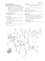
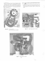
a. Disconnect spark plug wires at spark plugs. Remove plugs.
b. Remove the ten bolts securing cylinder cover to engine
body. Remove cover. See Figure 3-1
c. Remove the four hold-down nuts, washers and lockwashers securing intake and exhaust man ifo lds to cyl inders.
Remove manifolds. Remove intake manifold with carburetor attached . Remove carburetor if it requires servicing. Refer to applicable carburetor manufacturer's
specifications. Remove insul ato rs from intake side.
Discard gaskets.
Figure 3-2.
d. Remove the four bolts securing recoil starter to fan cover.
Remove starter to expose starter cup and fan belt pulley.
Figure 3-3.
e. Disconnect coupler attached to fan cover. Remove two
bolts securing coil cover to fan cover. Remove cover to
expose high tension coils.
Figure 3-3.
f. Remove the two bolts and spacers securing high tension
coils to fan cover. Remove coils with spark plug wires
attached.
g. Remove the two hold-down nuts, two attaching bolts
and lockwashers securing electric starter to engine body (if
so equipped) . Remove starter.
Remove starter.
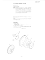
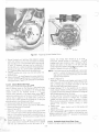
h. Remove the three bolts securing starter cup, fan belt
pulley and window plate (if instal led) to flywheel. Pull
outward and up on pulley to remove from flywheel.
Remove fan belt.
1. Remove the two Phillips screws securing ignition terminal
coupler and bracket to fan cover, and four bolts securing
fan cover to fan cover case. Remove fan cover to expose
flywheel.
Figure 3-6.
k. Remove the four bolts seCL'ring fan covercase to crankcase. Remove covercase.
Figure 3-7.
I. Remove the two screws securing stator assembly to
crankcase. Remove stator assembly.
Figure 3-8.
NOTE : Unless being serviced, stator assembly should be
stored inside flywheel to ensure retention of magnetic properties.
m. Remove the five hold-down nuts securing each cyl inder
head to cylinder. Rem ove cy linder heads.
Disca rd cylinder head gaskets.
Tool : 13 mm box spanner.
NOTE: Before proceeding any further check crankshaft for
bend and twist as follows:
1. Check for twist:
(a) Rotate engine to T.D.C. on No. 1 cylinder using a dial
indicator mounted on the cyl inder.
(b) Install and zero a degree wheel on the crankshaft.
(c) Rotate crankshaft 1800 The piston on No.2 cy linder
should be at T.D.C. Permissable tolerance is 20.
2. Check for bend on either end:
(a) Mount a dial indicator at the junction of the parallel
and tapered sections of the shaft.
(b) Zero the indicato r. Rotate the crankshaft one full
turn. Permissable runout is 0.003 inch on one rotation.
n. Remove the four hold-down nu ts securing each cylinder
to cran kcase. Remove cyl inders to expose piston and
connecting rod assemblies. Discard cylinder base gaskets.
Figure 3-10.
c
CAUTION: If disassembly is discontinued after cylinder or
piston removal, ensure that crankcase is kept
covered to prevent ingress of dirt or fore ign
objects to crankcase.
3-1
exhaust manifold
Cylinder Cover
Intake manifold
Fig. 3-2 Intake and Exhaust
Man ifolds Removed
Fig. 3-1 Cyli nder Cover
Removed
disconnect
Fig. 3-3 Recoil starter and high tensio n co ils removed
3·2
c
Fig. 3-4 Starter cup and fan belt pulley removed ., ... ;:,:
c
Fig. 3-5 Fan cover removed
3-3
Fig. 3-6
Removing flywheel
Fig. 3·7 Fan cover case removed
3·4
Fig. 3-SA
c
c
Stator a'ssembly
l--c
Fig. 3-8 Stator assembly removed
3-5
J
Fig. 3-9 Cylinder heads removed
Fig. 3-10
Cylinders removed
3-6
)
c
o. Refer to Section IV, Figure 4-7
Before removing pistons (5), ensure that the piston crown
is marked with an arrow directed toward the exhaust port.
If no arrow is legible, inscribe the piston crown accordingly. Using a suitable circl ip removal tool, remove one
of the two circlips (7) securing each piston pin (6) in
position. Use a prop ane torch or cloth soaked in hot water
and heat the pistons unt il warm to the touch ( 1200-1400
F). Use a soft drift to push the pins out from the opposite
side. Remove needle bearings ( 10) from connecting rods
sma ll end .
CAUTION : Exercise care when removing piston pins to
prevent damage to needle bearings. Keep bearings adequately protected until t ime of assembly. Figure 3-11.
p. Remove piston rings from piston ring groove, using a
su itable ri ng removal tool.
q. Remove the ten bolts, pl ai n washers and lockwashers
joining the two halves of crankcase. Separate crankcase by
pulling the two halves apart. Remove the crankshaft.
Remove the four seal retaining circlips from crankcase
Iower half. (Refer to Section V, figure 5-1).
CAUTION: Do not use a screw driver to pry the crankcase
apart. If necessary, use a soft hammer and tap the
case lightly on either end.
wear, cracks, and evidence of co rrosio n; attaching hardware and attachment holes for wear and condition of
threads. If it is necessary to dress the threads, use suitable
thread cleaning tools. Repair or replace damaged parts and
any parts that fa il to meet applicable specifications. Refer
to Section IV, Repair and Replacement.
b. Perform additional inspections as detailed in paragraphs
3.3.4 to 3.3.13.
3.3.4 Spark Plugs Inspection and Adjustment
a. Inspect spark plugs for general condition, cracked or
broken insu lators and burned electrodes.
Guide to spark plug serviceabi lity:
1. Center electrode burned brown indicates plug is
functioning normally.
2. Center electrode burned wh ite indicates the plug is too
low in thermal value. Discard plug and install new plug
of specified type.
3. Center electrode burned black indicates the plug is too
high in thermal va lue. Discard plug and insta ll new plug
of spec ified type.
b. Adjust spark plug gap to 0.6 to 0.7 mm. (0.023 to 0.025)
in). Bend the outside (ground) electrode only. Use a spark
plug wi re gauge to measure the gap. Discard plug if
electrode is burned exc-essively or if specified gap cannot
be maintained.
c. Inspect spark r;lug wires for condition of insulation;
rubber bushings for splitting or deterioration; tips for
security. Rep lace defective wires.
Figure 3-1 2
3.3 CLEANING AND INSPECTION
c
c
3.3.1 Cleaning
Prior to inspection clean all parts, except the magneto
assembly, by immersing an d soaking in a suitable cleaning
solvent or using specified methods. Clean the crankshaft
before clean ing othe r components, to protect bearings from
possible damage due to dirty cleaning so lvent. Thoroughly
dry all parts after cleaning.
Pay particular attention to the following special instructions:
a. Spark plugs:
Remove light carbon deposits by brushing lightly with a
wire brush. If plug is excessively dirty and proper clean ing
equipment is not ava ilable, install a new spark plug.
b. Pi ston ring grooves, piston crowns, cylinder heads:
Use the proper groove cleaning tool for clean ing piston
ring grooves. Normal cleaning methods should be sufficient fo r cleaning piston crowns and cylinder heads.
c. Spark plug holes and exhaust ports:
Carefully remove heavy ca rbon deposits from these areas,
using a soft metal (non-ferrous) scraper. Use a spark plug
tap to clean threads.
CAUTION: Do not scrape down to base metal su rfaces when
removing heavy carbon deposits. Exercise ca re
while cleaning spark plug holes, to prevent
damage to the threaded area.
d. Magneto:
Thoroughly dryclean the magneto using compressed air or
suitable clean ing materials. Ensure no moisture or oily
fi lm remains after clean ing.
3.3.5 Fan Covers
a. Inspect fins for cracks; fan fo r blade damage, freedom of
movement and evidence of binding. Dress out nicks or
dents. Replace fan if a blade is cracked or broken since the
balance wi ll be affected.
b. Inspect fan belt for stretch, fraying and deterioration.
3.3.6 Recoil Starter
a. Pull starter rope out and permit it to recoil. Do not let rope
snap back on recoil. Rope should pull out smoothly and
recoil without hesitation. A weak or incomplete recoil
indicates a defective or maladjusted main spring.
b. Check for smooth operation of pawls. When the rope is
pulled out, pawls should move outward; when the rope
recoils, pawls shou ld move inward.
c. Inspect handle and rope guide for general condition and
security of attachment.
3.3. 7 Electric Starter (if installed)
a. Inspect drive shaft and spring for condition, smooth
operation and security. Lubricate in accordance with
Lubrication Chart, Table 2-2.
NOTE: Disassembly or repair of electric starters shou ld be
performed by authorized dealers only. Replace
defective starters if overhau l facilities are not available.
3.3.8 Magneto Assembly
a. Inspect coil platefordamageandsecurity.
b. Inspect low tension generation coil(s) and lighting coils
for general condition and security.
c. Inspect contact breaker points and condensers for condition; breaker points for wear, burning or pitting. Serviceable points appear a greyish frosty co lor. If points are in
3.3.2 Inspection
3.3.3 General
a. After disassembly, clean all parts in accordance with
paragraph 3.3.1. Inspect al l parts for obvious damage,
3-7
0
Fig. 3-11 Removing pistons
0
Connecting rods
)
Fig. 3-12 Upper Crankcase half removed
3-8
2. If cylinder has been rebored and hor)ed, replace
defective piston with oversize piston as listed in Table
3-1
serviceable condition, the condenser can be considered
serviceable. Inspect oi l felt pads for condition and
security; lubricate in accordance with Lubrication Chart,
Table 2-2.
d. Inspect all electri cal connections for security; insu lation
for chafing and deterioration.
3.3.12 Crankshaft and Connecting Rods
a. Inspect threads on each enu of shaft. The mating nut on
the flywheel end of the shaft should turn on all the way by
hand without excessive looseness.
Use a suitable thread clean ing tool to remove burrs from
the threads. Replace worn nuts.
b. Check tapered surface of flywheel end of shaft for scoring
and wear. When placed on the shaft hand tight, th e
flywheel should not wobble.
c. Inspect keyway and Woodruff key for damage and wear.
Rep lace worn keys.
d. Inspect ball bearings for wear, free movement an d
security.
e. Using Vee blocks (2) on a flat surface, ~upport the
cran kshaft on the center main bearings. Mount dial
indicators at junction of tapered an d parallel sections of
the shaft and rotate crankshaft by the connecting ruJs.
Refer to Table 3-1 for to lerances.
f. Check crankshaft for bend or twist on the crankshaft
jou rnals. Use a dial indicator placed on the main bearing
journals. Zero the ind icato r. Rotate crankshaft one full
tu rn. Refer to Table 3-1 for tolerances.
g. Check connecting rod diameter at small end; side and
vertical clearance at large end . Refer to Tab le 3-1 for
method of inspection and tolerance.
h. Check con necting rod twist as follows:
1. Insert a bar, 100 mm long or any other co nvenient
length, into the connect ing rod small end. Centralize
the rod using a depth gauge and lock in position.
2. Support connecting rod hor izontally. Using a dial
indicato r measure the maximum height at opposite
ends of the bar when the rod is twisted to the right and
to the left. Any variat ion indicates co nnect ing rod
twist. Refer to Table 3-1 for tolerance.
1. Check connecti ng rod tilt as follows:
1. Repeat step h( 1).
2. Support co nnecting rod verti cally. Usi ng a dial test
indicato r, measure the amount of movement at ends of
bar when bar is tilted to the right and to the left. The
difference between the two readings ind icates the
amount of tilt. Refer to Table 3-1 for tol erance.
3.3.9 Flywheel Assembly
a. Inspect cam, governor we ight(s) an d spring(s) for general
cond ition and security; cam for wear, particularly at point
of con tact with governor weights.
b. Check flywheel ta per for snug fitt ing. When placed on
crankshaft hand tight, the flywheel should not wobble.
c. Inspect magnets for nicks, scores or burrs. Use a suitable
stone to smooth off high spots.
d. Inspect ring gear and teeth (if installed) for wear, general
con dition and security.
e. Lubricate cam, governor weight and sp ring in accordance
with Lubrication Chart, Tab le 2-2.
3.3.1 0 Cylinder Heads and Cylinders
c
a. Inspect cyl inder heads and cy linders for pitting, scoring
and evidence of corrosion.
b. Check cy linder heads fo r warp or distortion as fo llows:
1. Place cyl inder head, f lat side down, on a su rface plate
or suitable measu ring device.
2. Using a feeler gauge, measu re amount of distorti on at
poin t of contact between cylinder head and surface
plate.
Take a reading at each of the five locations between
cylinder head hold down studs.
Max imum al lowable distortion at any one location is
0.002 inch.
c. Check cy linders for distortion as follows:
1. Install a servi ceab le head on cy linder to be checked.
Do not install hold down nuts.
2. Using a feeler gauge, measure amount of distortion at
point of contact between cy linder head and cylinder.
Take a reading at each of the five locations between
cylinder head hold down studs.
Maximum allowable distortion at any one location is
0.002 inch.
d. Using a dial indicator or suitab le measuring device, check
inside diameter of cylinders. Cylinders, worn beyon d
standa rd tolerances, may be rebored to accomo date the
installat ion of oversize pistons. Refer to Table 3-1 fo r
standard and oversize f its and tolerances. The oversizes
listed in the table are the maximum al lowable. Discard
cy linders that requ ire boring in excess of tol erance shown.
Replace with serviceable cylinders.
3.3.13 Crankcase
a. Inspect cran kcase mat ing surfaces for deep scratches,
scoring and pitting.
b. Inspect bearing and oil sea l reta ining inserts for wear,
sco ring or conditions which could cause leaks.
c. Inspect attachi ng dowe I pins tor wear and security.
d. Discard crankcase if no rm al repair procedures are not
sufficient to correct defects.
NOTE: Rebo red cylinders should be honed with a fin e
finishing stone.
3.3.11 Pistons, Pins and Rings
a. Inspect pistons, pins an d ringsfo r sco ring andwear;piston
crowns for pitting, evidence of corrosion and distorti on.
b. Check diameter of pistons, pins and pin bore; pisto n ring
end and side clearances. Refer to Table 3-1 for method of
inspection and to lerances.
c. Discard any parts th at fail to meet applica ble specifications and note the following:
1. If cyl inder has been inspected and found serviceab le,
repl ace defect ive piston with new standard size piston .
3.3.14 Fits andTolerances
Table 3-1 lists standard fits an d tolerances to be checked
duri ng inspection of pisto ns, pis'ton pins, cy linders and
crankshaft. It also lists allowable oversizes of pistons and
rings. If suggested method of inspection is not available, use
sui tabl e measuring devices.
3-9
REPLACEMENT PAGE
MA RCH 1971
CCW Model340-400
Component
ccw 340
ccw 400
ccw 440
Cylinder
Connecting Rod, small end
big end
TABLE 3-1 (FITS AND TOLERANCES)
Std. Size
ln.
Mm
Tolerances
Inches
Minus
Plus
2.36
2.56
2.67
60
65
68
N/A
N/A
N/A
.0007
.0007
.0007
Dial Indicato r
.867
22
N/A
Dial Indicato r
1.261
32
N/A
.00 1
.014
.016'
N/A
.0003
.0008
.0004
side clearance
vertical clearance
twist
bend
Crankshaft
permissable misalignment due
to bend or twist.
Crankshaft, end float
Piston, at
ccw 340
ccw 400
ccw 440
2.36
2.56
2.67
Bottom of skirt
Piston Pin
Piston Ring, No. 1
groove clearance
end clearance
Piston Ring, No.2
groove clearance
end clearance
N/A
.0004
.0015
.003
Dial Indicato r
Measured at ends of bar
3.94" centred in small
end (See Manual)
Dial Indicato r
Measured at junction
of taper and parallel
sections (see manual) .
Dia l Indicator
.001
.0035
N/A
.003
Feeler gauge.
N/A
N/A
N/A
Micrometer
.UII
Piston Pin, c/1
Piston Pin Bore
Method of
Inspection
N/A
N/A
60
65
68
Top land
Remarks
.709
.709
.083
.083
18
18
.012
.007
.008
.004
.0047
.0004
.0003
.0025
.004
.004
.012
.0014
.003
.004
.012
3-10
N/A
N/A
N/A
N/A
N/A
N/A
N/A
N/A
Dial Indicato r
Micrometer
Feeler Gauges
SECTION 1V
r
REPAIR AND REPLACEMENT
4.1 GENERAL
4.3 RECOILSTARTER(SeeFigure4-2)
4.1.1 The repair and replacement instructions detailed in
this section are included to assist in the disassembly,
replacement of defective parts an d- assembly of major
sub-assemblies. It is not necessary to completely disassemble
the sub-assemblies unless inspection procedures reveal
defects. Perform only those steps necessary to gain access to
the defective part( s) and to effect the necessary repairs.
4.3.1 Disassembly
a. Untie the knot in the rope at rope handle ( 15). Remove
handle and allow the rope to recoil slowly into the case
( 12). Unscrew and remove rope guide ( 13).
b. Remove retaining nut (2), lockwasher (3) and flatwasher
(4) from threaded shaft of reel hub (10).
c. Manipulate friction plate (5) on reel hub until eye end of
return spring (7) aligns with retaining slot (22). Remove
friction plate.
d. Remove the three pawls (6).
e. Remove return sp ring (7), spring (8) and cup washer (9).
Note position of plain end of return spring in the spring
retaining hole in reel hub.
f. Remove reel ( 10) . Unwind the rope; lift and untie the
knotted end from center hub of reel.
g. Lift long rolled end of main spring ( 11) from the fixed
spring retaining pin in the case and carefully remove the
sp rmg.
h. Clean all parts, except rope, using a su itable cleaning
solvent. If rope requires cleaning, wash it in a so lution of
soap and water. Thoroughl y dry all parts after clean ing.
1. Inspect all parts for obvious damage and wear.
4.2 FAN COVER (Seefigure4-1)
4.2.1 Disassembly
c
c
a. Remove nut (2), lockwasher (3), and plain washer (4)
from threaded end of fan shaft. Spacer (5) is permanently
secu red to outer pulley (6) .
Tool: 19 mm box spanner, Locking tool, Part No.
43-0792-50.
NOTE: Drill one 1/4" hole in pulley to take pin of locking
tool.
b. Remove outer half (6) of fan belt pulley, spacers (7, 8, 9)
inner half ( 10) of pulley, and spacer ( 11) from shaft.
c. Tap Iightly on end of fan shaft to remove fan ( 16) from fan
cover.
d. Inner bearing (15) shou ld remain on fan shaft assembly
and can be removed by slid ing it off the shaft. To remove
outer bearing ( 12), turn the case over; use a suitable soft
drift to tap bearing out of retainer. Remove spacer ( 13) . It
is not necessary to remove snap ring ( 14) unless it is found
defective. Use su itable rem oval tool to remove snap ring.
e. Clean all parts, except bearinqs, usinq suitable cleaning
solvent. Wipe bearings clean, using a clean cloth moistened
with cleaning solvent. Thoroughly dry all parts after
clean ing.
4.3.2 Assembly
a. Replace defective parts.
b. Install main spring as follows:
1. Secure main spring winding tool, part number
43-0797-60, or equivalent tool. circular end up, in a
suitable bench vise.
2. Start with the long rolled end of main spring ( 11) and
wind spring into circular end of tool in a clockw ise
direction.
3. Remove tool from vise. Grasp the tool by its handle
and lower the tool, with spring installed, into case ( 12).
4. Secure the long rolled end of spring over the fixed
spring retaining pin. Remove winding tool. Apply a
light film of Lubripl ate, or equivalent, to spring.
c. Secure case, open side up, in bench vise.
d. Tie a knot at one end of the rope. Secure knotted end
around center hub of reel ( 10). Pull rope taut and wind
entire rope around reel in an anti-cl ockwise direction
until the free end protrudes through the notched section
of the reel.
e. Apply a light film of Lubripl ate, or equivalent. to center
hub of case and install the reel. Push down and rotate
4.2.2 Assembly
a. Replace defective parts.
b. Install snap ring ( 14) if it has been removed.
c. Install outer bearing (12). Turn case over; install spacer
( 13) and inner bearing ( 15). Ensure bearings are properly
seated with no evidence of bind in g. If necessary, use asoft
steel drift to tap bearings into position. Ensure that no dirt
or fore ign material enters bearings.
d. Reverse disassembly steps (a) to (c). Tighten retaining nut
securely, using lock tool No. 43-0792-50.
e. Check tan for proper operation.
4-1
/6
I~
J
1.
2.
3.
4.
5.
6.
7.
8.
9. Spacer
Inner pulley
Spacer
Outer bearing
Spacer
Snap ring
Inner bearing
Fan
Fan cover
Retaining nut
Lockwasher
Plain washer
Spacer
Outer pulley
Spacer
Spacer
FIGURE 4-1
10.
11.
12.
13.
14.
15.
16.
FAN COVER ASSEMBLY .
4-2
/6
1.
2.
3.
4.
5.
6.
7.
8.
9.
10.
11.
Starterpulley
Retaining nut
Lockwasher
Flatwasher
Friction plate
Pawl (each 3)
Friction plate return spring
Spring
Cup washer
Reel
Main spring
12.
13.
14.
15.
16.
17.
Case
Rope guide
Rope
Handle
Endpiece
Bolt, starter to fan cover
attaching
18. Lockwasher
19. Flatwasher
20. Bolt, starter pulley to flywheel attaching
21. Loc kwasher
22. Slot, return spring retaining
23. Hook, main spring retaining
FIG LIRE 4-2 RECOIL STARTER ASSEMBLY
4-3
.J
2
3
10
'-/..
11
'K
',
"-~~
·,
'~
~
5
14
I,
..._,
8. Lug plate
9. Flywheel
1.
2.
3.
4.
5.
Flywheel assembly
Snap ring
Cam
Snap ring
Washer
6. Governor weight
7. Governor spring
10.
11.
12.
13.
14.
Screw, lug plate attaching
Spring washer
Washer
Screw, governor stop
Spring washer
FIGURE 4-3 FLYWHEEL ASSEMBLY - 340S
4-4
c
c
4.5 FLYWHEEL ASSEMBL Y-KOKUSAN- MODELS
340E, 340G and all 400 MODELS (See Figure 4-4)
reel in an anti-clockwise direction until the hook (23)
engages with the free end of main spring. Tension wil l be
felt when reel and spring are properly engaged.
f. Rotate reel a maximum of three complete turns in an
anti-clockwise direction. Do not exceed three turns; hold
reel in this position and feed free end of rope through case
at the rope guide hole. Install rope guide. Loosely knot
the rope to prevent recoil.
g. Apply a light film of Lubriplate or equivalent to pawls (6)
and install them on the reel in the pawl retainers.
h. Install cup washer (9) flat side down, spring (8) and
return spring (7). Ensure that plain end of return spring is
properly engaged in the retaining hole in reel hub.
1. Install friction plate (5) over reel hub . Manipulate plate
until eye end of return spring engages and locks crosswise
in retaining slot (22).
J. Rotate friction plate until the three notches are aligned
with pawls when pawls are at the recoil position.
k. Install flatwasher (4) , lockwasher (3). and nut (2).
Tighten nut securely.
I. Untie the temporary knot in free end of rope and install
the rope handle. Tie a permanent knot and fit handle
securely.
m. Check starter for proper operation. When handle is pulled
outward, pawls should move outward.
4.5.1 Disassembly
NOTE: Complete disassembly of flywheel assemblies should
be performed by authorized dealers only. The
auto-advance mechanism is pre-set during manufacture and should require no further adjustment. If
inspection reveals faulty governor parts or defective
magnets, install a new flywheel assembly or return
flywheel to overhaul facility.
a. Remove snap ring (3) secu ring breaker point cam (4) to
flywheel collar, using a suitable snap ring removal tool.
Lift cam off collar. Check cam and collar for scoring and
wear; governor weight stops for wear and security.
Replace defective parts.
4.5.2 Assembly
a. Apply a light film of Lubriplate or equivalent to outer
surface of flywheel collar.
b. Reverse removal procedure.
c. Lubricate in accordance with Lubrication Chart, Table
2-2.
d. Check mechanism for proper operation.
NOTE: If main spring is to be installed without the use of a
spring winding tool, wind main spring into case in an
anti-clockwise direction. Clockwise installation on
the winding tool is necessary to ensure correct
anti-clockwise installation of the spring when tool is
placed upside down in the case.
4.6 STATOR ASSEMBL Y-SAWAFUJI - MODEL 340S
(See Figure 4-5)
NOTE: Complete disassembly of stato r assemblies should be
performed by authorized dealers only. Normal disassembly shou ld be restricted to removal and replacement of defective contact breaker point sets, oil felt
pads or condensers. If inspection reveals additional
maintenance requirements, install a new assembly or
return stator to overhaul facility.
4.4 FlYWHEEL ASSEMBL Y-SAWAFUJI-MODEL 340S
(See Fig. 4-3)
4.6.1 Contact Breaker Point sets
4.4.1 Disassembly
NOTE: Complete disassembly of flywheel assemb lies should
be performed by authorized dealers only. The auto
advance mechanism is pre-set during manufacture
and should require no further adjustment. If inspection reveals faulty governor parts or defective magnets, install a new flywheel assembly or return
flywheel to overhau I facility.
a. Remove snap ring (2) securing breaker point cam (3) to
flywheel collar, using a suitable snap ring removal tool.
Lift cam off collar. Check cam and col lar for scoring and
wear; governor weight stop screw ( 10) for wear and
security. Replace defective parts.
NOTE: Removal and installation procedure is applicable to
both point sets.
4.6.1.1 Removal
a. Loosen electrical terminal connector (28) securing condensor primary wire at contact breaker point set (7).
0 isconnect primary wire.
b. Remove retaining screw ( 18}.\ockwasher ( 16) an d washer
(17) securing contact breaker points to coil plate (2) .
Remove breaker point set.
4.6.1.2 Installation
a. Apply a light film of Lubriplate or equivalent to pivot
shaft.
b. Reverse removal procedure.
4.4.2 Assembly
a. Apply a light film of Lubriplate or equivalent to outer
surface of flywheel collar.
b. Reverse removal procedure.
c. Lubricate in accordance with Lubrication Chart. Table
2-2.
d. Check mechanism for proper operation.
CAUTION: Ensure no lu bricant gets on breaker points
during installation. Contaminated points will
burn during engine operation.
c. Adjust points to specified gap. Refer to Section V,
Paragraph 5.4.3.
4-5
1.
2.
3.
4.
5.
6.
7.
8.
9. Flywheel
Flywheel assemb ly with ring gear
Flywheel assembly, less ring gear
Snap ring
Cam
Washer
Governor Spring (2)
Governor weight (2)
Lug, sp ring to governor weight
attaching
10. Ring, governor weight attaching
11.
12.
13.
14.
15.
16.
Screw, lug plate to flywheel attaching
Spring washer
Ringgear
Bolt, ring gear
Spring washer
Window plate
)
FIGURE 4-4 FLYWHEEL ASSEMBLY (KOKUSAN MAGNETO) 340E, 340G, 400
4-6
26
27
-~.~,~-!
14
c
ir'J?-12
d~
1
f1
.\1
2
1
/
.
~~
w
4
22
c
28
1.
2.
3.
4.
5.
6.
7.
8.
9.
Stator assembly
Coil Plate
Primary Ignition Coil
Lighting co il
Condenser (White)
Condenser (Red)
PointSet
Oilfelt & Holder
Protector
10.
11.
12.
13.
14.
15.
16.
17.
18.
Coupler
Washer
Screw
Spring washer
Washer
Screw
Spring washer
Washer
Screw
19.
20.
21.
22.
23.
24.
25.
26.
27.
28.
Screw
Spring Washer
Screw
Washer
E Ring
Bracket. Coup ler
Rubber Bushing
Spade Connector
Spade Connector
Terminal Connector
c
FIG. 4-5
STATOR ASSEMBLY (SAWA FUJ I IGNITION)
4-7
~-/;4
12
l!~~r-13
f".,
29
1
31
"li
7
1. Stator Assembly
2
3.
·
4.
5
6._
7
8.
9·
1
o:
.
Coil
Plate. Generating Coli
LowTenslon
· Coli
Lighting (Red)
Condenser
. )
Con denser (Wh lte
Point Set
Oil. FeIt & Holder
Protector
Coupler
11. Washer
12 Screw
·
13_
14_
15_
16.
· Washer
Spnng
Washer
Screw
Spring Washer
17_ Washer
18. Screw
19_ Screw
Screw
2
o.
FIG. 4-6 (K OKUSA N IGNITION)
4-8
21_
22.
23.
24.
Screw
r
.
Spring Was~~ Coil Attaching
Bolt, lgnllt~late Attaching
Bolt, Col
25.
26.
27
.
28.
29.
30
·
31 .
32.
Washer Ignition Coil
Pr1mary
Cl amp
d Connector
Spa/ Connector
Spake t Coupler
Brae e ,
.
bber Bush mg
Ru . 1 Connector
Termma
c
1. Crankshaft ass'y
Ball bearing
Oil seal
Oil seal
Piston (note inscribed arrow)
Piston pin
Circlip
8.
9.
10.
11.
12.
13.
14.
2.
3.
4.
5.
6.
7.
Piston ring# 1
Piston ring# 2
Needle bearing
Washer
Spring washer
Nut
Woodruff key
FIGURE 4-7 PISTON ANO CRANKSHAFT ASSEMBLY
Fig. 4-8 Oil seals identificatio n
4-9
b. Remove retaining screw (15) or (19) as applicable, and
washer (16) securing condenser to coil plate (2) . Remove
condenser and oil felt pad (if attached). Check pad for
condition and replace if lubricating capacity is questionable.
4.6.2 Condensers and Oil Felt Pads
NOTE: Removal and installation procedure is applicable to
both condensers.
4.6.2.1 Removal
a. Loosen electrical terminal connector (28) and disconnect
primary wire at contact breaker point set (7).
.
b. Unsolder condenser wires at terminal on low tens1on
generation coil (3) and at connector on engine body. .
c. Remove retaining screw (15) and washer (16) secunng
condenser and oil felt pad (8) to coil plate (2). Remove
condenser and oil felt pad . Check pad for condition and
replace if lubricating capacity is questionable.
4.7.2.2 Installation
a. Reverse removal procedure.
b. Lubricate oil felt pad. Refer to Lubrication Chart, Table
2-2.
4.8 CRANKSHAFT (See Figure4-7)
NOTE: If inspection reveals maintenance requirements beyond outer ball bearing or outer oil seal remova l and
installat ion, install a new crankshaft.
4.6.2.2 Installation
a. Reverse removal procedure. Resolder condenser wires at
primary coil and ignition coupler.
.
b. Secure condenser primary wire to contact breaker po1nt
set at terminal connector (28)
c. Lubricate oil felt pad . Refer to Lubrication Chart, Table
2-2.
4.8.1 Oil Seal and Outer Bearing
4.8.1.1 Removal
a. Remove Woodruff key (14) from tapered end of crankshaft assembly, using suitable pliers or removal tool.
b. Remove oil seals (3) and (4). Seals are a snug fit, and can
be removed by sliding them along the shaft. Discard seals.
c. Remove outer bearings (2), one from each end of
crankshaft, using bearing puller or suitable removal tool.
4.7 STATOR ASSEMBL Y-KOKUSAN - MOOELS 340E,
340G, and ALL 400 MOOELS. (See Figure 4-6)
NOTE: Complete disassembly of stator assemblies should be
performed by authorized dealers only. Normal disassembly should be restricted to removal and replacement of contact breaker point sets, oil felt pads or
condensers. If inspection reveals additional maintenance requirements, install a new assembly or
return stator to overhaul facility.
4.8.1.2 Installation
NOTE: Keep bearings in the packaged condition or adequately protected from dust, dirt and other contammants
until ready for use.
4. 7.1 Contact Breaker Point Sets
Reverse removal procedure and note the following:
a. Bearings are a press fit on the crankshaft.
Install new bearings as follows:
1. Apply a light film of lubricating oil to crankshaft and
ball bearing inner race.
2. Preferred Method
The preferred method of installation is with the use of
an arbor press. Lay the new bearing on a face block
having a slot or hole slightly larger than the bearing
inner bore; press shaft down until bearing is firmly
seated.
3. Alternate Method
An alternate method of installation is with the use of a
soft tube. Use a suitable length of mild steel tubing,
accurately squared at the ends, with large enough
inside diameter to slip loosely over the crankshaft.
Start bearing on end of crankshaft. Using the tube,
gently tap the bearing down the shaft until bearing is
firmly seated.
NOTE: Removal and installation procedure is applicable to
both point sets.
4.7.1.1 Removal
a. Loosen electrical terminal connector (32) securing ignition wiring at contact breaker point set (7).
Disconnect the wires.
b. Remove retaining screw (18) or (20) as applicable,
lockwasher (16) and washer (17) securing breaker point
set to coil plate (2). Remove breaker point set.
4. 7.1.2 Installation
a. Apply a light film of Lubriplate or equivalent to pivot
shaft.
b. Reverse removal procedure . ..,.
CAUTION: Ensure no lubricant gets on breaker points
during installation. Contaminated points will
burn during engine operation.
CAUTION: Prevent damage to the shaft and bearings until
installation. Ensure that bearing is started true
and not cocked on the shaft and that no loose
metal chips are allowed to fall into bearings.
b. Use new oil seals. Oil seals are marked with an arrow
indicat ing direction of crankshaft rotation. Correct direction of arrow rotation is clockwise from flywheel end and
anti-clockwise from power take-off end. (R efer to Figure
4-8). Ensure seal is installed with cup facing inward and
arrow directed as shown in the illustration. Exercise care
when installing seals, to prevent seal damage and leaks
during engine operation.
c. Adjust points to specified gap. Refer to Section V,
Paragraph 5.4.3.
..
4. 7.2 Condensers and Oil Felt Pads
NOTE: Removal and installation procedure is applicable to
both condense rs.
4. 7.2.1 Removal
a. Loosen electrical terminal connector (32) at contact
breaker point set (7). Disconnect the condenser lead wire.
4-10
I
INSERT PAGE
MARC H 1971
c
CCW 440 DENSO IGNITION
4.9 STATOR ASSEMBLY -Repair & Replacement
NOTE : Complete disassembly of stator assemblies should
be performed by authorized dealers only. Normal
disassembly shou ld be restricted to removal and
replacement of contact breaker point sets, oil felt
pads or condensers. If inspection reveals additional
maintenance requirements, install a new assembly
or return stator to overhaul facility.
CAUTION: Ensure no lubricant gets on breaker points
during installation. Contaminated points will
burn during engine operation.
c. Adjust points to specified gap. Refer to Section V,
Paragraph 5.4.3.
4.9.2 Condensers and Oil Felt Pads
NOTE: Removal and installation procedure is ap plicable to
both condensers.
4.9.1 Contact Breaker Point Sets
4.9.2.1 Removal
a. Loosen electrical terminal connector at contact breaker
point set (7). Disconnect the condenser lead wire.
b. Remove retaining screw (23), and washer (21) securing
condenser to coil plate (2). Remove condenser and oil
felt pad (if attached). Check pad for condition and
replace if lubricating capacity is questionable.
NOTE: Removal and installation procedure is appl icable to
both point sets.
4.9.1.1 Removal
a. Loosen electrical terminal connector securing ignition
wiring at contact breaker point set (7) .
Disconnect the wires.
b. Remove retaining screw (22), lockwasher (21) and
washer (20) securing breaker point set to coil plate (2).
Remove breaker point set.
4.9.1.2 Installation
a. Apply a light film of Lubriplate or equ ivalent to pivot
shaft.
b. Reverse removal procedure.
4.9.2.2 Installation
a. Reverse removal procedure.
b. Lubricate oil felt pad. Refer to Lubrication Chart, Table
2 2.
c
Fig. 4-9
4-11
INSERT PAGE
MARCH 1971
4.10 FLYWHEEL ASSEMBLY-CCW 440
(See Fig. 4-12)
0
4.1 0.1 Disassembly
NOTE: Complete disassembly of flywheel assemblies
should be performed by authorized dealers only.
The auto advance mechanism is pre-set during
manufacture and shou ld requ ire no further adjustment. If inspection reveals faulty governor parts or
defective magnets, install a new flywheel assembly
or return flywheel to overhaul facility .
Remove snap ring (5) and govern or weight (4) to release the
breaker point cam.
Lift cam off collar. Check cam and collar for scoring and
wear; governor weight stop screw for wear and security.
Replace defective parts.
4.1 0.2 Assembly
a. Apply a light film of Lubriplate or equivalent to outer
surface of flywheel collar.
b. Reverse removal procedure.
c. Lubricate in accordance with Lubrication Chart, Table
2-2.
d. Check mechanism for proper operation .
2
8
(:)
4-12\
SECTION V
REASSEMBLY, TESTING AND ADJUSTMENTS
5.1 GENERAL
5.1.1 Prior to reassembly, check all parts for cleanliness and
serviceab ility in acco rdance with paragraph 3.3.
5.1 .2 During assembly, tighten all screws, bolts and nuts
secu rely. Ensure that correct torque values are applied where
spec ified. Do not overtorque.
b.
c.
5.1.3 Use only new gaskets and seals during assemb ly
procedure.
d.
5.1.4 During assembly, lubricate all bearings and friction
surfaces with new, clean two stroke engine oi l.
e.
5.1.5 If procedu res are discontinued during assembly,
ensure that intake and exhaust ports, spark plug holes and all
other open ings are covered to prevent ingress of dirt or
foreign objects to cylinders and crankcase.
cover end to right hand side; insert the four seal retaining
ci rclips.
Install the crankshaft into lower half of crankcase with
externally threaded (flywheel) end of shaft toward right
hand side. (See Section Ill, figure 3-12). Ensure th at seal
retaining circl ips do not become dislodged.
Apply a liberal amount of two-stroke engine oil to
crankshaft and bearings.
Apply a good quality, non hardening sealing com pound
evenly to sealing surfaces of both crankcase halves.
Reseat the crankcase halves; ensure that the two dowel
pins are properly engaged with mating holes in crankcase
upper half.
Refer to Figure 5-2 ..
Install four 8 x 65 and six 8 x 45 attaching bolts, washers
and Ioc kwashers. Install the fa ur Ianger bo Its at locations
2, 3, 4 and 7. Loosely tig hten the four bolts at locations
"A", then torque all bolts down evenly to 15-18 footpounds maximum in accordance with sequence shown
in the illustration.
5.2 REASSEMBL V
5.2.2 Pistons, Piston Rings and Pins (See Figure 5-3)
a. Lubricate piston pin needle bearing with two-stroke
5.2.1 Crankcase and Crankshaft (See Figure 5-1)
a. Pl ace crankcase lower half on work bench with flanged fan
Oilseal Retaining circlips
Fig. 5-1 Crankcase Lower Half
5-1
REPLACEMENT PA GE
MARCH 1971
®------1
1--------{
3 f - - - --
J
r----1.7
-\
-o
s::
11>
~
11>
.s::
$:
>
u.
6 l---------1
1 - - - --
-{
2 1------i
A
)---------\ 4
A
Fig. 5-2 Crankcase Bolt Torquing Sequence
d. Install piston rings in ring grooves, using a suitable ring
installing tooL Ensure that piston ring gap is correctly
positioned at the ring groove locating pin.
e. Repeat steps (a) to (d) for second piston .
engine oil and install bearing into connect ing rod small
end .
b. If both piston pin retaining circlips have been removed
from piston, use a suitable tool and install a circlip at one
piston pin bore.
NOTE: The chromium plated ring should be installed in the
top groove
c. Use a propane torch or cloth soaked in hot water and heat
piston until warm to the touch ( 120 to 140°F). Ensure
that the arrow on piston crown is directed toward the
exhaust port and align piston pin bore with center bore of
connecting rod. Lubricate piston pin and, using a soft
drift, push pin into piston until it bottoms on the installed
circlip. Exercise care to prevent damage to needle bearing.
Install remaining circlip.
5.2.3 Cylinders (See Figure 5-4)
a. Install new base gaskets over cylinder hold down studs.
b. Cylinders are identified by the letters "L" (left hand) and
"R" (right hand) stamped on the cylinder flange. Locate
right hand (No.1) cylinder at flywheel end of crankcase.
c. Lubricate pistons, rings and cy linders with two-stroke
engine oiL
d. Place a su itable wooden block between piston and
Piston Rings
Locating Pin
c
Fig. 5-3 Installing Pistons, Rings and Pins
5-2
REPLAC EMENT PAGE
MARCH 1971
. DO NOT TIGHTEN TO FULL TORQUE AT THIS
STAGE.
crankcase to steady the piston. Using a piston ring
compressing too l, compress rings flush with piston.
e. Slide cylinder over piston and ring assembly. Remove ring
compressing tool.
f. Repeat steps (c). (d) and (e) for No.2 cylinder.
g. Install cylinders on the crankcase and fit flat washers,
spring washers and securing nuts. Tighten the nuts
evenly to hold the cylinders firmly on the crankcase.
.
h. Install inlet manifold using new gaskets and tighten
securely to ensure alignment of the cyl inder and
manifold flanges.
1.
Finally tighten the cylinder flange nuts as per Figure
5-5. to recommended torque of 15-18 lbs.-ft.
-----
Fig. 5-4 Installing Cylinders
®
3
CD
"C
1:
"C
1:
NO: 2
w
.....
.....
w
a;
NO: I
Q)
..c
3:
>-
0
a,
.::.:.
"'
1-
-
~
Q)
3:
0
c..
LL
~
~
@)
'-
Fig. 5-5 Cylinder Hold-down nut torquing sequence
5-3
@)
REPLACEMENT PAGE
MARCH 1971
5.2.4 Cylinder Heads (See Figure 5-6)
a. Install new cylinder head gaskets over cylinder head
hold down studs.
b. Install cylinder heads over hold down studs with
machined side facing inwards and cylinder cover attaching brackets facing toward intake ports.
c. Refer to Figure 5-7.
Install the ten washers, lockwashers, and hold-down
nuts; install the two long internally threaded nuts above
the intake ports at location (5) .
Torque nuts down evenly to 15-18 foot-pounds maximum in accordance with the sequence shown in the
illustration.
cylinder
heads
Fig. 5-6 Installing Cylinder Heads
NO.2
NO. I
CD
®
CD
®
-c
-c
-
r:::
r:::
(I)
(I)
0
.D
0
~
....ca
....
(I)
;:::
0
c..
0
(J)
a;
(I)
C3)
..r:::
;:::
>
u.
CS)
CS)
Fig. 5-7 Cylinder head hold-down nut torquing sequence
5-4
c
5.2.5 Stator Assembly (See Figure 5-8)
5.2.6 Fan Cover Case and Flywheel (See Figure 5-9)
a. Install and secure stator to engine crankcase using two
Phillips head screws. Position ignition wire bundle in the
recess provided, and install rubber grommet
a. Install and secu re fan cover case to crankcase using four 8
x 28 bolts, plain washers and lockwashers.
b. Place a Woodruff key in the slot on the crankshaft Ensure
flywheel center bore and tapered end of crankshaft are
free of oil or grease. AI ign keyway and key; slide flywheel
Coil Plate retainings screws
Fig. 5-8 Stator assembly installed
Fig. 5-9 Fan cover backing plate and flywheel installed
5-5
5.2. 7 Fan cover, Starter Cup and Fan Belt Pulley (See Figure
5-1 0)
a. Install and secure fan cover to fan cover case using four 8 x
35 bolts, plain washers and lockwashers. Secure ignition
terminal coupler and bracket using two Phillips head
screws.
on to shaft as far as it will go. Rotate flywheel to ensure
freedom of movement with no evidence of binding. Lock
the flywheel using CCW Tool #43-0798-40; install flat
washe r, lockwasher and nut. Tighten nut to 40-50 pounds
feet maximum torque. Set timing to proper specifications.
Refer to paragraph 5.4.4.
Fig. 5-10
Fancover, Starter
Cup and Fan belt pulley installed
Fig. 5-12
Fig. 5-11
Recoil Starter Instal led
5-6
High Tension Ignition Installed
5.4 ADJUSTMENTS
b. If a window plate was removed during disassembly,
replace it behind fan belt pu \ley with a Iip facing outward.
Install and secure fan belt pulley and starter cup to
flywheel using three 6 x 22 bolts and lockwashers. Install
fan belt and adjust to proper tension. (Refer to Section II,
Pnragraph 2.6.2.)
5.4.1 Carburetor (Refer to applicable manufacturer's
specifications)
5.4.2 Spark Plugs (Refer to Section Ill, Paragraph 3.3.4)
5.4.3 Contact Breaker Points (See Figure 5-13)
a. Remove recoil starter, starter cup and fan belt pulley.
b. Remove window plate (Kokusan magneto only).
c. Loosen applicable breaker point retaining screw.
d. Adjust breaker points gap to 0.014±.002 inch . Use a feeler
gauge to measure the gap.
e. Tighten breaker point retaining screw.
f. Check engine ignition timing. See Paragraph 5.4.4.
g. Replace window plate, starter cup, fanbelt pulley and
recoil starter.
5.2.8 Electric Starter (if so equipped)
a. Install and secure electric starter to hold down studs at
covercase. Secure to crankcase using two 8 x 20 bolts,
washers and lockwashers.
5.2.9 Ignition Coils-Testing and Installation
a. Coil output can be tested on a Merc-0-Tronic or other
comparab le analyzer. See Table 1-1 for specifications. A
three needle air gap tester may also be used. See Table 1-1.
Note: -A 12 vo!t battery will be required on the older
model of Merc-0-Tronic analyzers.
b. Install and secure high tension ignition coils to fan cover
using two 6 x 65 attaching bolts and spacers. Connect low
tension wires to igniti.on coupler.
c. Install and secure coil cover using two 6 x 10 bolts, plain
washers and lockwashers. Figure 5-11
5.4.4 Engine Ignition Timing (See Figure 5-14)
After engine overhaul or whenever contact breaker points
have been replaced or adjusted, check and/or adjust ignition
timing to ensure continued engine operating efficiency.
5.4.4.1 Preferred Method
The recommended method of engine ignition timing is with a
dial indicator and a timing light having a self contained
battery. This method is considered the most co nvenient
means of determining piston position in respect to true top
dead center.
Time the engine as follows:
a. Remove recoil starter, starter cup and fan belt pulley;
remove window plate (if installed).
b. Remove spark plugs; disconnect ignition at coupler.
c. Install a suitable dial indicator into No. 1 cylinder spark
plug hole.
d. Rotate flywheel to locate No.1 piston position at true top
dead center. True top dead center is that point on the
indicator scale where the pointer begins to reverse
direction of motion. Zero the dial indicator at true T.D .C.
e. Refertofigure5-13.AdjustNo. 1 cylinderbreakerpoint
gap to 0.014 inch. This point set has red ignitio n wiring.
Connect one lead of a timing light to the red wire at
ignition coupler and the other lead to ground.
f. Rotate flywheel until pointer of dial indicato r reaches
0.015 inch before tru e top dead center. At this instant the
timing light should go out to indicate breaker points just
starting to open.
If necessary, adjust ignition coil plate to the right or to the
left until the light goes out. Secure ignition co il plate in
this position; recheck piston travel to verify timing
accuracy.
NOTE: If coil plate cannot be adjusted enough to accurately
set No.1 cylinder timing, recheck breaker point gap.
Gap may be re-adjusted to 0.0 14±.002 inch to obtain
desired timing sequence. Breaker point gap must
remain within specified tolerance.
5.2.1 0 Recoil Starter (See Figure 5-12)
a. Insta II and secu re reco i I starter to fan cover using four 6 x
21 bolts, flat washers and lockwashers.
c
5.2.11 Intake and Exhaust Manifolds
a. Install two new intake manifold gaskets and the two
insulators over intake manifold hold down studs.
b. Install two add itional new gaskets over insulators and
mount intake manifold to hold-down studs. Secure with
four flatwashers, lockwashers and hold-down nuts. Do not
overtorque the nuts.
c. Install two new exhaust manifold gaskets and mount
exhaust manifold to hold-down studs. Secure with four
fliltwashers, lockwashers and hold-down nuts.
Do not overtorque the nuts.
5.2.12 Covers
a. Install and secure cylinder cover and adapter to engine
using four 6 x 10 and six 6 x 12 attachment bolts and
lockwashers; install the four shorter bolts at intake and
exhilust manifo ld sides of cover. Start each attachment
bolt before tightening any bolts; then tighten all bolts
securely. Ensure spark plug wires are properly secured as
shown in figure 5-12.
5.2.13 Engine Installation
Cl Install engine to app licable mounting location; attach
muffler and tailpipe; connect electrical wiring and controls.
b. Remove protective plugs from spark plug holes; install
specified plugs and connect high tension leads.
c. Check engine for proper operation. Refer to paragraph
5.3.
g. Remove dial indicator and install it into No.2 cylinder
spark plug hole. Disconnect timing light from ignition
coupler.
h. Adjust No. 2 cylinder breaker point qap to 0.014 inch.
This poin t set has red ignition wiring. Connect one lead
of timing light to the red wire at coupler and the other
lead to ground.
1. Locate No. 2 piston position at true T.D.C. Refer to
procedural step (d).
5.3 TESTING AFTER OVERHAUL
5.3.1 General
A five to ten percent power loss may be expected on a newly
overh<luled engine until it has been subjected to a su itable
run-in period . Carefully run the engine at varying eng ine
speed'> lor the first twenty-five hours of operation.
5-7
Coil Plate retainings screws
Fig. 5-13
Adjusting Contact Breaker Points
instant, the timing light should go out or suitable
instrument should activate to indicate No. 1 cylinder
breaker points just starting to open. If necessary, adjust
ign it ion coil plate to the right or to the left until the
cor rect indication is given. Secure igt:}i1l,9n coil plate in this
position . Recheck timing to verify accuracy.
NOTE : If coil plate cannot be adjusted erwugh to accurately
set No. 1 cylinder timing, recheck breaker point gap.
Gap may be re-adjusted to 0.014±.002 inch to obtain
desired timing sequence.
e. Refer to Figure 5-13.
Adjust No. 2 cylinder contact breaker point gap to 0.014
inch. This point set has red ignition wiring. Connect one
lead of timing light or suitable instrument to the red
wire at coupler and the other lead to ground.
f. Rotate flywheel 1goo to the opposite set of reference
marks. Adjust flywheel until No.2 piston is approaching
top dead center and the nearest go reference Iine is aligned
with the zero reference line on fan cover.
At th is instant the timing light should go out or suitable
instrument should activate to indicate No. 2 cylinder
breaker points just starting to open. If necessary, breaker
po ints may be re-adjusted to 0.014±.002 inch to obtain
desired t iming sequence. Recheck timing to verify
accuracy.
g. Replace window plate, starter cup, fan belt pulley and
recoil starter.
h. Rep lace spark plugs; check engine for proper operation.
1. Using a stroboscope, check ignition timing setting, au to
advance mechanism when fully advanced, in accordance
with Specifications, Table 1-1.
J. Rotate flywheel until pointer of dial indicator reaches
0.015 inch before true T.D.C. At this instant the timing
light should go out to indicate breaker points just starting
to open. If necessary, point gap may be re-adjusted to
0.014±.002 inch to obtain the desired timing sequences.
Breaker point gap must remain within specified tolerance. Recheck piston travel to verify timing accuracy.
k. Replace window plate, starter cup, fan belt pulley and
recoil starter.
I. Replace spark plugs; check 'engine for proper operation.
m. Using a Stroboscope, check ignition timing setting, auto
advance mechanism.-when fully advanced in accordance
with specifications, Table 1-1.
5.4.4.2 Alternate Method (See Figure 5-14)
As an alternate method of engine ignition timing, use the two
sets of reference marks on the flywheel and the top dead
center (zero) reference line marked on the fan cover. The
reference marks on the flywheel include a "T" which
indicates piston position at top dead center when aligned
with the zero reference line on fan cover, and so, go and 100
reference lines in advance of top dead center. One set of
reference lines is 1goo opposed to the other set. If using the
alternate method, time the engine as follows:
a. Remove spark plugs; disconnect ignition at coupler.
b. Remove recoil starter, starter cup and fan belt pulley.
Remove window plate (if installed).
c. Refer to Figure 5-13.
Adjust No. 1 cylinder contact breaker point gap to 0.014
inch. This point set has white ignition wiring. Connect one
lead of a timing light having a self contained battery, or
su1table Instrument to the white wire at coupler and the
other lead to ground.
';;d. Rotate flywheel until No. 1 piston is approaching top
dead center and the nearest SD reference Iine is aligned
with the zero reference line on the fan cover. At this
5.4.4.3 Crankshaft Angle Versus Piston Travel
Table 5-1 lists piston position relative to crank angle.
5-8
_)
c
Fig. 5·14
c
Setting Engine Ignition Timing-Alternate Method
TABLE 5-1
CRANK ANGLE VERSUS PISTON TRAVEL
Crank Angle
Distance from
Top Dead BTDC
so
0.006
0.008
0.011
0.015
0.018
0.023
0.028
0.033
0.038
0.044
0.051
0.058
0.065
0.073
0.081
0.089
0.099
0.108
0.118
0.129
0.139
0.150
0.162
0.174
0.186
0.198
6
7
8
9
c
10
11
12
13
14
15
16
17
18
19
20
21
22
23
24
25
26
27
28
29
30
5-9
j
TABLE 5-2
TORQUE SPECIFICATIONS
Location
Type
Size
Lbs. Ft.
Crankcase
Cylinder Head
Cylinder to Crankcase
Flywheel to Crankshaft
Fan Pulley
Screws
Nuts
Nuts
Nut
Nut
8mm .
Bmm.
8mm .
14mm.
12 mm.
12-15
15-18
12-15
45-50
28-31
TABLE 5-3
METRIC/LINEAR CONVERSION TABLE
to Obtain
(Unknown)
Multiply
(Known)
by
Millimeters (mm)
Inches (in.)
Centimeters (em)
Inches (in.)
Kilometers (km)
Miles(mi)
Meters (m.)
Feet (ft.)
0.03937
25.4
.3937
2.54
.62 14
1.609
3.281
.3048
Inches
Millimeters
Inches
Centimeters
Miles
Kilometers
Feet
Meters
Cubic Centimeters (cc.)
Cubic Inches (cu. in.)
Liters (I.)
Gallons (qal.)
Liters (I)
Quarts (qt.)
Cubic Centimeters (cc.)
Fluid ounces (fl. oz. )
.061
16.387
.264
3.785
1.057
.946
.0339
29.57
Cubic Inches
Cubic Centimeters
Gallons
Liters
Quarts
Liters
Fluid Ounces
Cubic Centimeters
Kilograms (kg.)
Pounds
Grams (g.)
Ounces (oz.)
2.205
.4536
.03527
28.35
Pounds
Kil ograms
Ounces
Grams
Metric Horsepower (ps)
Brake horsepower (bhp.)
Kilogram-meter ( kg.-m.)
Foot-pounds (ft.-lbs.)
Square millimeters (sq.mm)
Square inches
1.014
.9859
7.235
.1383
0.00155
645.2
bhp.
ps.
Foot-pounds
kg.-m.
sq. in.
sq. mm.
(:)
TABLE 5-4
LIST OF APPROVED CARBURETORS
CCW Model
Model
Carburetor Manufacturer
Fuel Return
Yes
340
340
340
340
400
400
400
400
WR 6
HR92
HR99A
1408.5/013586
HR101A
HR100A
WR6
16Y10/013599
Wa lbro
Tillotson, Diaphragm
Ti llotson, Diaphragm
Bend ix Zenith, Float Ch amber
Tillotson, Diaphragm
Tillotson, Diaphragm
Walbro, Diaphragm
Bendix, Diaphragm
* Not Required
5-10
No
*Yes
No
Yes
*
No
Yes
Yes
*