1
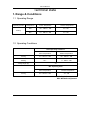
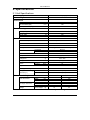
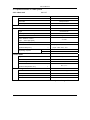
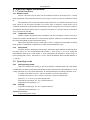
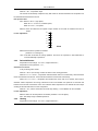
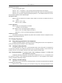
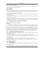
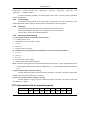
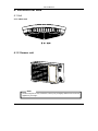
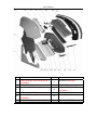
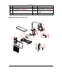
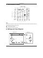
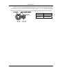
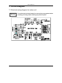
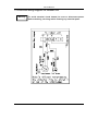
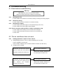
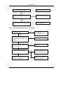
Service Manual
SPLIT TYPE CEILING CASSETTE AIR CONDITIONER
Service Manual
AA-2117
1
Service Manual
CONTENTS
1. Range & Conditions
Operating Range……………………………………………………………………………...2
Operating Conditions ………………………..……………………………….………….…2
2. Specifications
Unit Specifications………………………………………………………….…………………3
Specifications of Main Parts………………………………………………………………….4
Specifications of Other Parts……………………………… ………………………………..6
3. Functions
Control Functions……………………………………………………………………………..7
Operating Mode……………………………………………………………………………….7
Protect Functions……………………………………………………………………………..9
Other Functions ……………………………………………………………………………..10
Temperature Table of Prevent Point ………………………………………………………12
4. Dimensional Data………………………………………………………………..13
5. Performance Charts……………………………….………………..………….15
6. Refrigerant Flow Diagram…………………………………………….……....16
7. Circuit Diagram
Electrical Wiring Diagram for Indoor Unit…………………………………………………18
Electrical Wiring Diagram for Outdoor Unit…………………………………….………..19
8. Troubleshooting
Check before Troubleshooting……………………………………………….…………….20
Air Conditioner Does Not Work…………………………………………………………….20
Some Parts of Air Conditioner Do Not Work……………………………………………...22
Air Conditioner Operates, But Abnormalities are Observed. …………………………...24
Sensor is Defective………………………………………………………….………………26
9. Checking Electrical Components. …………………………………………..26
2
Service Manual
Technical Data
1. Range & Conditions
1.1 Operating Range
Operating Modes
Temperature
Indoor Temperature
Outdoor Temperature
Max.
32℃ DB/27℃ WB
43℃ DB
Min.
21℃ DB/15℃ WB
21℃ DB
Cooling
1.2 Operating Conditions
Rated Operating Conditions
Indoor Temperature
Outdoor Temperature
Cooling
27℃ DB/19℃ WB
35℃ DB/24℃ WB
Heating
20℃
7℃ DB/6℃ WB
Tubing Length (m)
4.0
Max. Operating Value
Indoor Temperature
Cooling
32℃ DB/23℃ WB
Outdoor Temperature
43℃ DB
DB: Dry-bulb temperature
WB: Wet-bulb temperature
3
Service Manual
2. Specifications
2.1 Unit Specifications
Power supply
220V~ 60Hz (single phase)
Rated voltage
V
220
Btu/h
9000
Performance
Rated capacity
3
m /h
480
l/h
1.0
V
198~242
A
W
W/W
4.5
980
2.65
Air circulation(High)
Moisture removal (High)
Electrical rating
Voltage range
Operating current
Power input
E.E.R / C.O.P
Features
Controls / Temperature control
Microprocessor / I.C thermostat
Control unit
Infrared remote control transmitter
Timer
ON/OFF 24 hours
Fan speed
Indoor /Outdoor
High, Medium, Low, Auto /High
Horizontal
Vertical
Airflow direction
Manual
Auto
Air filter
Anti-mold, washable
Compressor
Rotary-type (Hermetic)
Refrigerant
/g
R22 / 600
Refrigerant control
Capillary tube
Indoor
Outdoor
Noise
dB-A
dB-A
40
52
Pipeline connection manner
Max. pipeline length
Refrigerant
tubing
diameter (in)
Flare
m
9.0
Narrow tube
mm
6.35 (1/4”)
Wide tube
mm
9.52 (3/8”)
Indoor unit
Dimensions & Weight
Unit dimensions
Package dimensions
Weight
Height
Width
Depth
Height
Width
Depth
Cross weight
mm
mm
mm
mm
mm
mm
kg
Outdoor unit
675
430
265
820
535
385
16
25
Data subject to change without notice
4
Service Manual
2.2 Specifications of main parts
2.2.1 Indoor unit
AA-2117
Controller
Part No.
JUK6.672.848
Controller
Microprocessor
Fuse
250V T3.15A
KK10B-C2
Remote controller
Fan &
Fan motor
Type
Cross-flow fan
Quantity / Diameter / Length
mm
Fan motor model
1 /Ф86 /640
Welling: RPG20E-2
Pole / Rotation of motor
4 / 1250
(rpm, 220V High speed)
Rated power output
W
16
Coil resistance
red-purple: 290±15%,
Ω
(Ambient temp 20℃)
purple -white :403±15%
μF
1.0
VAC
450
Operating capacitor
Louver motor
Type
Step motor
Model
ZTC1.01
Rated voltage
V
Coil resistance
Ω
(Ambient temperature 25℃)
12VDC±10%
80Ω±10%
Heat exchanger
Fin
Aluminum fin / Copper tube
Row
1
Row pitch
mm
2
Face area
m
1.4
0.144
Data subject to change without notice
5
Service Manual
2.2.2 Outdoor unit
AA-2117
Controller PCB
Part No.
-
Fuse
-
Compressor
Controller model
Highly: SD134SN-H3AU
Compressor power input
Compressor oil / Amount
W
CC
Overload protector
Highly: DIAMOND MS-56 / 270
Highly: BF840-KB
Compressor locked rotor amperes
A
Ω
Coil resistance (Ambient temp 20℃)
Operating capacitor
895
μF/ VAC
21
Highly: C-R: 3.53, C-S: 4.02
Highly: 25/ 450
Fan & Fan motor
Type
Amount / Diameter
Propeller fan
mm
Fan motor model / amount
1 /Ф400
Welling: YDK19-6V-2/
Pole / Rotation of motor (220V, High speed) rpm
6 ..860
Rated power output
W
Coil resistance (Ambient temp 20℃)
Ω
19
white-gray :254±15%,/
brown-white:150±15%/
Safety devices
Open : 130±8℃
Close: 82±15℃
μF
2.0
VAC
450
Operating capacitor
Heat exchanger
Fin
Aluminum fin / Copper tube
Rows
Fin pitch
1
mm
2
Face area
m
1.4
0.177
Data subject to change without notice
6
Service Manual
2.3 Specifications of other parts
Indoor unit
Transformer
DB-13-01
Indoor temperature
KTEC-41-C12
Thermal resistor
Coiled pipe
Resistance temperature 25℃
KTM-41-C9
10
K
Ω
Power supply length (m)
/ cross section
AWG16
Rated value
15A, 250VAC
Power relay
JQX-102F-012-P
Coil rated voltage,
12V±10%, 20A
Current coil resistance(20℃)
160Ω
2.5
Outdoor unit
Data subject to change without notice
7
Service Manual
3. Control Specifications
3.1 Control functions
3.1.1 Switches input:
Press on / off button in the off mode. The air conditioner is turned on and works at 24℃ in sweep
mode automatically. Press the button when the unit is running or in test run mode, air conditioner is turned
off.
Press the button over four seconds until the buzzer beeps twice. Air conditioner enters the test run
mode. Users can use the remote controller to turn off the units or change the running mode. The air
conditioner will start the normal operation automatically if the test running time is for more than 15minutes.
Air conditioner will stop and exit the test run mode when users press on / off button which is on the indoor
unit or on the remote controller.
3.1.2
Temperature control:
Remote controller will transmit indoor temperature and other information to indoor unit every 3
minutes. If the master controller MCU can ’t receive remote signal for 10minutes, air conditioner will control
the running automatically by indoor temperature sensor.
When indoor temperature sensor is being used, It has 3℃ temperature compensation in heating
mode. There is no temperature compensation in cooling and dehumidification mode.
3.1.3
Sleep mode:
For better comfort in sleeping and energy saving. Temperature will be adjusted automatically when
the sleep mode is set. The set temperature will increase 1℃ after running 1 / 2 hour in cooling and
dehumidification mode, and 1℃ after another 1 / 2 hour. Temperature will decrease 2℃ after running 1 / 2
hour in heating mode, and 2℃ after another 1 / 2 hour. The set temperature will be controlled between 16
℃ and 30℃.
3.2 Operating mode
3.2.1
Auto-operating mode:
When air conditioner stars running or the set temperature is adjusted under this mode. Master
controller MCU can select running mode automatically by indoor temperature and set temperature. It runs in
cooling mode when Tr≥Ts (Tr: Room temperature, Ts: Set temperature) and in heating mode when Tr<Ts.
In heating mode, When Tr≥Ts+3℃ lasts for 15minutes. It turns into cooling mode.
In cooling mode, when Tr≤Ts-2℃ lasts for 15 minutes. It turns into heating mode.
When Ts-2℃< Tr < Ts+3℃,it turns into original mode.
Temperature control range: 16℃-30℃; Original value:24℃;
Temperature control precision:±1℃;
3.2.2
Cooling:
Temperature control range: 16℃-30℃; Original value:24℃;
Temperature control precision:±1℃;
Characters on control:
4-way reversing valve closes:
8
Service Manual
When Tr≥Ts+1℃, compressor runs.
When Tr≤Ts℃, compressor stops.
The control circuit will stop compressor only after it has run at least 5minutes.The compressor can
be restarted 3minutes later the turn-off.
Fan speed control:
Auto: When Tr>Ts+2℃, high speed;
When Ts+1℃≤Tr<Ts+2℃,medium speed;
When Tr< Ts+1℃, low speed.
Manual: Users can select the fan speed of high, medium or low level as needed in the turn-on
status.
Louver adjustment:
6
5
4
3
2
1
Close
Manual: Set the louver position as needed.
(Position 1-6 in the figure.)
Auto: In the first 20 minutes of cooling operation. The louver is at position 4. After 20minutes, it
runs automatically to position 6.
3.2.3
Dehumidification:
Temperature control range: 16℃-30℃; Original value:24℃;
Temperature control precision:±1℃;
Characters on control:
4-way reversing valve closes.
When Tr≥Ts+2℃,the running mode is the same to the cooling operation.
When Ts-1℃< Tr < Ts+2℃, compressor and external fan motor run continuously. And internal fan
motor runs between low wind for 10 seconds and breeze for 20 seconds continuously.
When 15℃< Tr < Ts-1℃, compressor and external fan motor work for 3 minutes, then stop for
9minutes. When compressor is running, internal fan motor runs between low speed for 10 seconds and
breeze for 20 seconds. Internal fan motor runs at breeze while compressor is off. Internal fan motor stops
working 30 seconds later the turn-off of compressor.
When Tr≤15℃, indoor and outdoor unit both stop working . Louver blades can be controlled.
Louver adjustment:
Manual: Users can set the position as needed. (Positions 1-6 in the figure)
Auto: The sweep range is fixedaat position 6.
3.2.4
Heating
Temperature control range: 16℃-30℃; Original value:24℃;
9
Service Manual
Temperature control precision:±1℃;
Characters on control:
4-way reversing valve opens.
When Tr≤Ts-1℃, compressor , 4-way reversing valve and external fan motor all open .
When Tr≥Ts+1℃, compressor and external fan motor both close. Indoor fan motor blows breeze.
When Trc (Trc: The indoor coiled temperature) drops blow F℃, Air conditioner enters into cool- airflow prevention operation; Pause indicator lights.
Fan speed control:
Manual: Users can select the fan speed of high, medium or low level as needed in the turn-on
status.
Auto: When Tr< Ts-2℃, high.
When Tr≥Ts-2℃,medium.
Louver adjustment:
Manual: Users can set the position as needed.
(Positions 1-6 in the figure)
Auto: When Trc<39℃,the sweep range is at position 5.
When Tr≥42℃, the sweep range is at position 4.
When 39℃≤Tr<42℃,the sweep range keeps at original position.
Compressor control:
The control circuit will stop compressor only after it has run at least 5 minutes. Compressor can be
restarted 5 minutes later the turn-off.
3.3 Protect functions
3.3.1
Delay-starting protection for the compressor.
Compress will restart working 3 minutes (5 minutes in heating) later the turn-off of compressor or
power-off to keep the pressure balance of the cooling system.
3.3.2
Cooling air flow protection:
In heating operation, when Trc<F℃,and compressor stops or the running time of compressor is
not more than 5 minutes. Air conditioner will enter into the cool-air-flow protection. Louver runs into the
position 6 and can ’t be controlled. Internal fan motor stops and pause indicator lights.
3.3.3 Freeze-prevention: To prevent indoor heat exchanger freezing in cooling and
dehumidification operation.
Compressor will stop running when it runs at least 10 minutes and Trc≤-2℃. If compressor is off
for more than 6 minutes, or the coiled pipe temperature rises above 8℃ and compressor is off at least 3
minutes. Compressor will restart working.
3.3.4
Heating overload working:
When Trc≥A℃, the unit enters into overload protection. And indoor fan speed should be adjusted
to a higher level automatically.
When Trc≥B℃, outdoor fan stops. And it will restart working when coiled pipe temperature drops
10
Service Manual
to D℃. Air conditioner will exit overload protection when coiled pipe temperature drops blow E℃. Indoor fan
motor resumes to the normal status.
Compressor will stop when the coiled pipe temperature is above C℃ and the build-up time of
compressor running is for more than 5 minutes.
3.3.5
Defrost:
A: Defrost conditions.
a. Indoor unit enters into overload prevention and outdoor unit stops. When outdoor fan motor runs for more
than 10 minutes, and the build-up time of compressor running is for more than 50 minutes, Toc≤A-1℃
( Toc: Coiled pipe temperature of the outdoor unit.)
b. Not overload, but Toc drops blow -17℃ for 30 seconds. The build-up time of compressor running is for
more than 25 minutes.
c. The build-up time of compressor running is for more than 3 hours. And Toc drops blow -2℃ for 5 minutes.
Trc≤G-2℃ and Trc≤(Tr+H)℃.
d. The build-up time of compressor running is for more than 3 / 2 hours. And it reaches the condition of the
unit stopping. Toc drops blow -2℃ for 3 minutes(overload).or Toc≤-2℃ and Trc≤G+2℃ (not overload).
e. The build-up time of compressor running is for more than 50minutes.
Toc ≤-2℃, Trc drops at least 3℃ and Trc≤G℃, Trc≤(Tr+H) ℃.
It will defrost under the one of the conditions.
B. Defrost:
Compressor and outdoor fan motor will stop working after entering into defrost running. 55
seconds later, 4-way reversing valve will close. Another 5 seconds, compressor starts running. When the
time of the compressor running is for more than 10 minutes or outdoor coiled temperature is above 20℃,
Compressor stops. 55 seconds later, 4-way reversing valve will open. Another 5 seconds later, compressor
and outdoor fan motor will restart working and exit defrosting operation. In defrosting operation, the time of
compressor running is at least 3 minutes. Cool airflow prevention and heat blowing are both efficient.
3.3.6
Troubleshooting display and prevention.
a. Pause indicator flashes quickly --- The driver or the control current of the louver is abnormal. And the
louver blades do not work.
b. Timer indicator flashes quickly --- The circuit of PG motor is abnormal; air conditioner stops.
c. Running indicator flashes --- The circuit of outdoor coiled temperature sensor is abnormal. The unit can’t
run in heating mode.
d. Pause indicator flashes --- The circuit of the temperature sensor is abnormal. The unit runs in 24℃.
e. Timer indicator flashes --- The circuit of the coiled pipe of indoor temperature sensor is abnormal. The
unit can’t run in heating mode.
3.4 Other functions
3.4.1
Auto-diagnosis
Test terminal on the main panel is shorted. The Auto-diagnosis functions are in the following steps
when the power is turned on.
Buzzer beeps 1s → No output 0.5s → Running indicator on 0.5s → Timer indicator on 0.5s →
11
Service Manual
No output 0.5s → Compressor 0.5 → Outdoor fan motor 0.5s → 4-way reversing valve 0.5s → Electric
heating 0.5s → Indoor fan motor 0.5s → Flap-a0.5s → Flap-b0.5s → Flap-c0.5s → Flap-d0.5s → No
output 0.5s → Complete output 1s.
In the Auto-diagnosis operation, the buzzer beeps if the circuits of the two indoor temperature
sensors are abnormal.
3.4.2
Timer saving:
The time-shortening terminal on the main panel is shorted when the unit is powered on. The
buzzer beeps twice and the master controller CUP runs as 60 times as the former speed.
3.4.3
HA input:
Posed with 200-300ms high level on the HA input end, the unit is turned on.
Posed with 500-600ms high level on the HA input end, the unit is turned off.
The unit runs in the former mode when restarted.
3.4.4
Auxiliary electric heating:
(1) The starting conditions of auxiliary electric heating.
a.
In heating or Auto mode.
b.
Compressor runs for more than 1 minute.
c.
Tr≤14℃.
d.
Ts-Tr≥6℃.
e.
Indoor fan motor is running.
(2) Auxiliary electric heating will be closed under the one of the following conditions.
a.
Tr≥18℃.
b.
Ts-Tr≤2℃.
c.
Trc≥A-2.
d.
Indoor fan motor stops working.
e.
The unit enters into defrosting operation.
Note: The electric heating will be off when the temperature reaches point C, and it will be restarted when
the coiled pipe temperature of indoor unit drops blow D-1℃ and it is satisfied with all the conditions
of (1).
(3) Defrost when electric heating is running.
If electric heating is running or the turn-off time is less than 10 minutes. It will enter into defrosting
operation and indoor fan blow breeze for 1 minutes.
(4) The unit is off when electric heating is running.
If electric heating is running or the turn-off time is less than 10 minutes. The indoor fan motor will
blow breeze for 1 minute.
3.5 Temperature table of preventing point
Model
AA-2117
A
B
C
D
E
F
G
H
49
52
65
44
42
32
36
24
12
Service Manual
4. Dimensional data
4.1 Unit
4.1.1 Indoor unit
4.1.2 Outdoor unit
Note:
The above figures are only schematic, and they may be slightly different from the actual
appliances you bought.
13
Service Manual
Exploded view for indoor unit
NO.
NAME
CODE
1
WIND-ABSORPTION BAR BRACKET
ASSEMBLY
11
2
AIR FILTER
12
INDOOR FAN
13
LEFT FILTER BRACKET
ASSEMBLY
14
COVER
3
WIND-ABSORPTION BAR
4
AIR GUIDING BOARD
5
FAN MOTOR
ASSEMBLY
6
RIGHT FILTER BRACKT ASSEMBLY
UPPER
COVER
15
14
16
BEARING ASSEMBLY
ASSEMBLY
TRANSFORMER
INDOOR
ELETRIC
Service Manual
CONTROL ASSEMBLY
7
INDOOR FAN MOTOR
17
Air outlet guid
8
EVAPORATOR
ASSEMBLY
18
DRAIN CANAL ASSEMBLY
Air supply shelf
Ass’y
19
DRAIN
BOARD
9
10
Air shutter Ass’y
20
Exploded view for outdoor unit
15
CANAL
INSTALL
Service Manual
5. Performance Charts
A
t
n
e
r
r
u
c
g
n
i
t
a
r
e
p
O
( )
(℃)
O u td o o r in le t te m p e r a tu r e ( D B ) ( ℃ )
Note:
Over prevention operates to protect the air conditioner when the outdoor ambient temperature reaches an
abnormally high level while in heating mode.
●……Points of rating condition
Note: The speed of the indoor unit is high.
6. Refrigerant Flow Diagram
Outdoor unit
Indoor unit
Service valve
Compressor
Joint
Pipe
Indoor
heat
exchanger
Outdoor
heat
exchanger
Strainer
Service valve
Pipe
Capillary tube
16
Joint
Service Manual
Thermal insulating of refrigerant pipeline
To prevent heat loss and condensed water from dropping on the floor, the wide and narrow tube of
air conditioner should be wrapped with thermal insulating materials. For using capillary tube, and the
tubes are in low temperature, the thickness of thermal insulating materials shall be more than 8mm.
17
Model
AA-2117
Narrow tube
Ф6.35mm(1/4”)
Wide tube
Ф9.52mm(3/8”)
Service Manual
7. Circuit Diagram
7.1 Electrical wiring diagram for indoor unit
Warning
To avoid electrical shock hazard, be sure to disconnect power before
checking, servicing and/or cleaning any electrical parts.
18
Service Manual
7.2 Electrical wiring diagram for outdoor unit
Warning
To avoid electrical shock hazard, be sure to disconnect power
before checking, servicing and/or cleaning any electrical parts.
19
Service Manual
8. Troubleshooting
8.1 Check before troubleshooting
Warning:
High-voltage will result in electric shock or death.
Always cut off the power before checking and maintaining.
8.1.1
Check power line
To check whether the power line is connected correctly according to the wiring diagram.
8.1.2
Check unit wiring
To check whether the inter-unit wires are connected correctly.
8.1.3
Check power supply
To check whether the power supply is in the specified range (220±10%).
To check whether the power supply is being supplied.
8.1.4 Check connector and lead wire of indoor and outdoor units.
To check whether the insulating cover of the lead wire is damaged.
To check whether the lead wire and the connector are connected well
To check wires.
8.2 The air conditioner does not work
8.2.1
A.
Leakage protector is open or fuse is burnt.
Setting leakage protector to “ON”, it opens immediately (can not reset).
There is possibility of ground fault.
Check insulation resistance (The insulation resistance shall be more than 2MΩ).
B.
Leakage protector is OFF.
Disconnect unit wires from terminal
No
Poor insulation performance
block of outdoor unit. And measure
Measure the insulation resistance of
insulation resistance of outdoor unit.
the electric parts of outdoor unit.
Disconnect unit wires from terminal
No
Poor insulation performance
block of indoor unit. Unplug the unit
and
measure
the
Measure the insulation resistance of
insulation
the electric parts of outdoor unit.
resistance of indoor unit.
20
Service Manual
C. The fuse is open in several minutes after turning air conditioner on.
Check the rated power of fuse.
No
Replace it with a proper one
No
Replace indoor fan motor.
No
Replace transformer.
Yes
Check the resistance of indoor fan
motor coil.
Yes
Check the resistance of transformer
coil.
8.2.2
The indoor and outdoor units do not work.
Check power supply
No
2. Check the breaker.
Yes
Check if something residue cover
1. Power failure
Yes
Clean it.
on transmitting part of the remote
controller.
No
Check if infrared receiver on
Yes
Clean it.
indoor unit is dirt.
No
Check fuse on indoor PCB Ass’ y.
Yes
Check the resistance of fan
motor coil of indoor unit.
No
Parts of indoor PCB Ass’ y or
Measure the resistance of
switches are defective.
power transformer.
21
Service Manual
8.2.3
Only outdoor unit does not work:
Check the set
1. The set temperature is too
temperature.
high for cooling operation.
Yes
2. It is too low for heating
Adjust the set
temperature.
operation.
Measure the voltage between
terminal No.1 and No.2 on the
Ok
terminal block (220V±10%)
Outdoor
unit
is defective.
No voltage indication.
PCB Ass’ y of indoor unit is defective.
8.2.4
Only indoor unit does not work.
Indoor PCB Ass’ y is defective.
8.3 Some parts of the air conditioner do not work
8.3.1
Only indoor fan does not work.
Check the fan rotation
Not rotate
Check if foreign matter is in
the fan cover.
Ok
Check if fan motor is broken
Measure the resistance of motor coil.
or foreign matter in bearing.
Ok
Check the capacitor of fan motor.
8.3.2
Only louver motor does not run.
Measure the resistance of the louver motor coil.
22
Check the connector.
Service Manual
8.3.3
Only outdoor fan motor dos not run.
Not rotate
Check the fan rotation
Check if foreign matter is in
the fan cover.
Ok
Check if fan motor is broken
Measure the resistance of motor coil.
or foreign matter in bearing.
Ok
Check the capacitor of the fan motor.
8.3.4
Compressor does not run.
Overload protector activates.
Check compressor capacitor.
Measure
the
resistance
The temperature of compressor is
of
too high.
compressor coil.
Measure the resistance of
power
Refrigerant is
relay coil.
Yes
not enough.
No
Measure if power supply voltage is
Rotor may be blocked.
too low.
23
Fill it.
Service Manual
8.4 Air conditioner operates, but abnormalities are observed
8.4.1
Bad shifting between cooling and heating mode
(Not available in cooling type).
Remote controller may be detective.
Measure the coil resistance of 4-way reversing valve.
Cooling
Heating
Ok
Check the voltage between terminal No.5
4-way reversing valve
is defective.
and N0.2 on the terminal block (AC220)
NO voltage
PCB Ass’ y of indoor unit is in error.
Cooling
Heating
Measure the voltage between terminal No.5 and No.2 on the terminal block (ov).
24
Service Manual
Poor cooling or heating phenomena.
Poor cooling
Is the temperature
(heating)
set properly?
Change the set temperature.
performance
Reduce heat (cool) source or
The heating (cooling)
change the air conditioner
load is too large.
Refrigerant
with large power.
4-way reversing valve fails.
Replace it
Refrigerant is not enough.
Filling it
Capillary tube is blocked.
Replace it.
Compressor is in error.
Replace it.
Service valve is not open
Open
completely.
completely.
The air filter is blocked.
Clean it.
flow is not
enough
Air circulating
capacity
is
it
not enough.
Fan running speed
Change it to “high’
is at “low”.
or “medium”.
Connection between indoor
Wide and narrow tubes
and outdoor units is in poor
are
thermal-insulated.
separately.
Cooling air -flow
4-way reversing valve is defective.
Cooling
The pause indicator is on.
airflow
Replace it
Replace
protector is no
use.
thermal-insulated
the
electric
controller of indoor unit.
Temperature
sensor
indoor coil is defective.
Note:
25
of
Replace the sensor.
Only in heat pump air conditioner.
Service Manual
8.4.2 Over cooling or heating.
Check the set temperature.
8.5 Sensor is defective
8.5.1
Temperature sensor of indoor heat exchanger is defective.
The timer of indoor
The sensor is
unit is flash.
open or short.
Replace it.
Definition of open or short circuit of sensor (thermal resistor):
Short circuit: The protective cover of a lead wire has been damaged, and the exposed wire is
touching another metal parts. Or both lead wires have become exposed and are
touching each other. Or the circuit inside the temperature sensor is closed.
Open: The lead wires are broken, or the circuit inside the temperature sensor is open.
9. Checking Electrical Components
9.1 Measure insulation resistance
The insulation is in good condition if the resistance exceeds 2 M
Ω.
9.1.1 Power supply wires
Clamp the ground pins of the power plug with the lead clip of the
insulation resistance tester and measure the resistance by placing a
probe on either of the power wires. (Fig. 1)
Then measure the resistance between the
ground wire and the other power wire. (Fig. 1)
9.1.2 Indoor unit
Clamp an aluminum plate fin or copper tube with the lead clip of the
insulation resistance tester and measure the resistance by placing
a probe on each terminal screw on the terminal plate. (Fig. 2)
Note that the ground line terminal should be skipped for the check.
26
Service Manual
9.1.3 Outdoor unit
Clamp a metallic part of the unit with the lead clip of the
insulation resistance tester and measure the resistance by
placing a probe on each terminal screw where power supply
lines are connected on the terminal plate. (Fig. 2)
9.1.4 Measurement of Insulation Resistance for
Electrical Parts
Disconnect the lead wires of the desired electric part from
terminal plate. Capacitor, etc.
Similarly disconnect the connector. Then measure the insulation
resistance. (Fig. 3 and 4)
Note:
Refer to electric wiring diagram.
If the probe can’ t enter the poles because
the hole is too narrow then use a probe with
a thinner pin.
9.2 Checking continuity of fuse on PCB ass”y
Remove the PCB ass’ y from the electrical component box. Then
pull out the fuse from the PCB ass’ y. (Fig. 5)
Check for continuity using a multimeter as shown in Fig. 6
9.3 Checking motor capacitor
Remove the lead wires from the capacitor terminals, and then
place a probe on the capacitor terminals as shown in Fig. 7.
Observe the deflection of the pointer setting the resistance
measuring range of the multimeter to the maximum value.
The capacitor is “good” if the pointer bounces to a great extent
and then gradually returns to its original position.
The range of deflection and deflection time differ according to the
capacity of the capaci
27