1
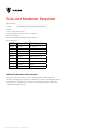
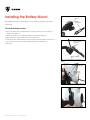
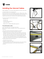
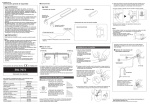
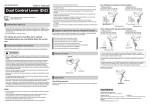
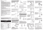
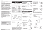
Electric Shimano™ Dura-Ace
(Di2) Installation
For Madone 2010 Series 6 with Di2 integration
These instructions explain how to install Shimano’s electronic Dura-Ace shifting system on
the 2010 Madone series 6, which is fully integrated for Di2. For the 2010 Madone Series 4,
Series 5, and 2008-09 Madone Series 6, please follow the Shimano external installation
instructions.
These instructions are a supplement to the Trek Madone service manual and are to be used
in conjunction with the Shimano set-up instructions. Before installing any Di2 component,
review the Shimano installation instructions.
For full set up, tuning, and adjustment of Shimano Di2 please see www.shimano.com.
Please save these instructions for future reference. Also check www.trekbikes.com for
updates.
Note about performing mechanical work on bicycles:
Many people think of bicycles as simple machines, almost toys. However, modern bicycles
use high-tech materials and designs that rely on correct maintenance and precision
workmanship. If any part on the bicycle is worn, corroded, rusted, loose, or damaged in
any other way, replace the part. If you do not have the correct tools or experience, do not
perform the tasks in this manual; take your bicycle to your dealer for service.
In some cases we provide several methods of checking the tightness or connection of parts.
The most preferable of these is always the one with the most precision. In other words,
correct mechanical work requires that all screws be tightened with a torque wrench.
Incorrect mechanical work on your bicycle could lead to damage or premature breakage of a
part, which could cause you to fall and lead to serious injury or death.
These instructions are written for an experienced mechanic. If you need further information,
refer to your bicycle owner’s manual, the instructions in a bicycle mechanic’s handbook, or
consult your dealer.
Table of Contents
Tools and Materials Required....................................................................................................................1
Preparing the Frame.................................................................................................................................... 2
Installing the Battery Mount ................................................................................................................... 3
Installing the Internal Cables .................................................................................................................. 5
Joining the Connectors.............................................................................................................................. 7
Installing the Crankset and Adjusting the Derailleurs.......................................................................8
ii TREK SERVICE INFORMATION
4 December 2009
Tools and Materials Required
Madone 6 Series
419125
Di2 Mounting Hardware Kit; TCG Part Number
Heat Gun
1.5, 2.5, 4, 5 mm allen wrenches
Torque wrench with drivers for 1.5, 2.5, 4, 5 mm allen
9mm box end wrench
Shimano Di2 Installation and Adjustment Instructions
Shimano Di2 parts:
TCG PN Shimano PN
Description
415892
EW-7975
Electric cable
415885
SM-EW79A-E
Electric cable
415881
FD-7970
Front derailleur
415887
RD-7970
Rear derailleur
415878
ST-7970
Shift/brake lever set
415893
SM-BTR1
Battery
415894
SM-BCR1
Charger
TL-EW01
Plug tool
SM-EC79
System checker
Additional information and instructions
Shimano has created an online resource for working with Di2 including technical
information and diagrams, a tutorial, and a certification program. You should watch at least
the tutorial before starting these procedures. You can find this information at this link:
http://di2certified.shimano.com
1 TREK SERVICE INFORMATION
4 December 2009
Preparing the Frame
If the bike is already set up with other parts, the frame will have to be partially stripped. If
you are working with a bare frame, go to Step 3.
To prepare the frame
1. Remove the shift inner-wires, shift housing, shift housing stops, bottom bracket guide and
front derailleur inner-wire tube.
2. Remove the cranks, derailleurs, shifters, bottom bracket bearings, seals, and shields.
3. Follow the Shimano instructions to install the Di2 front derailleur, rear derailleur, and
shifters (and for a bare frame, any supporting parts).
2 TREK SERVICE INFORMATION
4 December 2009
Installing the Battery Mount
On a 2010 Madone Series 6, the Di2 battery is mounted to the underside of the bottom
bracket shell.
Base-end
Shimano
mounting-bar
To install the battery mount
1. Remove the rubber sleeve and the Shimano mounting-bar from the base-end using a
1.5mm wrench (Figure 1).
2. With a 1.5 mm allen wrench, install the Madone mounting-bar (Figure 2).
3. Attach the base-end to the Madone frame mount (Figure 3).
Figure 1. Base-end and mounting-bar removed
4. Route the electric cable through the slot in the frame mount, through the inner-wire exit
hole in the frame, and out the bottom bracket shell (Figure 3 and Figure 4).
(continued)
Screws for 1.5 mm
allen wrench
Madone mountingbar
Figure 2. Base-end with Madone mounting-bar
attached
Derailleur inner-wire hole
Bottom bracket
inner-wire guide
hole
Figure 3. Madone frame mount attached to base-end
with electric cable exiting the bottom bracket shell
Figure 4. Madone mounting-bar attached to frame
3 TREK SERVICE INFORMATION
4 December 2009
5. Where the screw is usually inserted for the bottom bracket inner-wire guide, thread in
(but do not fully tighten) the 12 mm M5 screw.
6. Apply a small drop of light-duty thread-locker (such as blue Loctite® 242) to the nut to
Long screw
Box end
wrench
with nut
prevent loosening.
7. Install the long screw though the hole for the front derailleur inner-wire (Figure 5).
8. Using a box end wrench, insert the nut into the bottom bracket to meet up with the screw
(Figure 5).
Double check the routing on the battery-pack electric cable to be sure it is not pinched
and is lying comfortably in the guide.
9. Snug both mounting screws (Figure 6) to 17-26 Lb•in (2-3 Nm).
DO NOT OVERTIGHTEN!
Figure 5. Attaching screw to nut through inner-wire
hole of frame
Mounting
screws
Figure 6. Mounting screws holding base-end and
Madone mounting-bar to frame
4 TREK SERVICE INFORMATION
4 December 2009
Installing the Internal Cables
With the 2010 Madone Series 6, the Di2 is fully integrated. This means the electric cables
run inside the frame for a clean, aerodynamic look.
Each electric cable has a color-coded band that corresponds to a mating connector on the
junction. Each electric cable also has a metallic flag noting the component to which it should
be attached. To reduce noise from the electric cables vibrating against the frame while
riding, the electric cables that run inside the frame have zip-ties around them (Figure 7).
The Shimano Di2 internal cable kit includes these parts:
Figure 7. Anti-noise zip-ties on electric cables.
• RD electric cable
Junction A
• FD electric cable
• ST electric cable with Junction A
• Junction electric cable
• Battery mount (see Installing the Battery Mount, pages 3-4)
To install the electric cables
Disconnect the battery before connecting the electric cables.
Only use Shimano Di2 plug tool TL-EW01 to join the connectors. Follow the Shimano
instructions.
1. Connect the ST electric cable, with Junction A (Figure 8), to the shifters.
Junction B
Figure 8. Madone with Di2 showing locations of
junction boxes
2. Install the down tube electric cable (from Junction A to Junction B).
Starting from the front inner-wire entrance of the top tube (Figure 9), feed the electric
cable back to the head tube and then down the down tube to the bottom bracket shell.
If the electric cable does not make it to the bottom bracket shell, pull the electric cable
out and slide an inner-wire through the same route. With electrical tape, attach the
connector of the electric cable to the head of the inner-wire. Gently pull the inner-wire
(with the electric cable taped to it) into the down tube and out the bottom bracket shell.
3. Plug the downtube electric cable into Junction B.
The connectors are color-coded.
4. Install the rear derailleur electric cable.
Starting from the dropout inner-wire exit (Figure 10), feed the electric cable toward the
Figure 9. Electric cable going into the front entrance
of the top tube
bottom bracket shell, and pull the connector out of the bottom bracket shell.
(continued)
Figure 10. The electric cable for the rear derailleur
passing through the dropout
5 TREK SERVICE INFORMATION
4 December 2009
5. Install the front derailleur electric cable.
Feed the electric cable from the top side through the front derailleur inner-wire hole
toward the bottom bracket shell (Figure 11), and pull the connector out of the bottom
bracket shell.
6. Connect the electric cables to the mating color connections of Junction B.
7. Install the split frame plug onto the electric cable and slide it down the cable to seal the
top tube (Figure 9). Also install the frame plugs to seal the down tube (Figure 12).
Figure 11. The electric cable passing through the front
derailleur inner-wire hole
Figure 12. Plug in down-tube cable entrance hole
6 TREK SERVICE INFORMATION
4 December 2009
Joining the Connectors
The procedure joins and seals the electrical connections of the system. Disconnect the
battery before connecting the electric cables.
To join the connectors
1. Install the battery.
2. Follow the Shimano instructions to check the connections.
Be sure the rear derailleur and front derailleur are functioning.
3. Disconnect the battery.
4. Disconnect each of the connectors and slide a heat-shrink tube onto one electric cable of
each connection.
Note: the red connector is larger in diameter and requires the larger heat-shrink tube.
5. Reconnect each connector.
6. Check the connections again.
7. Disconnect the battery.
8. At each connection except the front derailleur (see following note), slide each piece of
heat-shrink tubing until it is centered over the connection.
Note: The cable for the front derailleur is just barely long enough, especially for 53T or
54T chainrings. If you center the tubing on the front derailleur conection, the cable may
not be long enough. Instead, align the tubing flush with the end of the connector nearest
the derailleur.
9. Using a heat gun, evenly apply heat to each piece of heat-shrink tubing until it shrinks and
seals its connection.
10. Re-check the function of both derailleurs.
7 TREK SERVICE INFORMATION
4 December 2009
Installing the Crankset
and Adjusting the Derailleurs
To install the bottom bracket and crankset
1. Feed the electric cables back into the bottom bracket shell and up into the down tube.
2. Spread the electric cables to allow installation of the bottom bracket shield.
Make sure the front derailleur electric cable is routed under the bottom bracket shield.
This will maximize the length of the front derailleur electric cable.
3. Re-install the shield, bottom bracket bearings, and crankset.
4. Follow the Shimano Di2 Adjustment and Setup instructions to tune the shifting.
8 TREK SERVICE INFORMATION
4 December 2009