1
)I I-f. Il.B
•
•
Model 467
Time to Pulse Height
Converter and SCA
Operating and Service Manual
PHYSICS -111- LAB.
286 Le Conte Hall
lA. FILE COpy
NOT FOR LOAN
•
$); t uc; ~.
71-/0 -
3/80
Model 467
Time to Pulse Height
Converter and SCA
Operating and Service Manual
•
This manual applies to instruments marked
"Rev 21" (on rear panel) .
......'1
"- .l_t:~~&_~~1. . ,', ~ .?'; /
.... ,
Printed in U.S.A.
.;~a:.~.
....... ~ . . .
2t:..f-""'";<-
•
2908 2.5C 0878
,
iii
•
CONTENTS
Page
WARRANTY·
v
PHOTOGRAPHS
vi
1, DESCRIPTION
1
1.1. Purpose and Features
1.2. Operation
1.3. Logic • • • .
2. SPECIFICATIONS
3.
•
2
2.1. Performance
2.2. Controls
2.3. Inputs
2.4. Outputs
2.5. Electrical and Mechanical
3
3
3
INSTALLATION
4
3.1. General • .
4
4
4
5
5
3.2. Connection to Power
3.3. Connection into a System
3.4. Linear Output Signal Connections and Terminating Impedance
3.5. Logic Signal Connections
4. OPERATING INSTRUCTIONS
4.1.
Time to Pulse Height Conversion
4.2. Single Channel Analysis
5. CIRCUIT DESCRIPTION
5.1.
5.2.
5.3.
5.4.
General . . . . '.'
TPHC Circuit . . •
Single Channel Analyzer Circuit
Auxiliary Logic
6. MAINTENANCE . .
6.1.
6.2.
Testing Performance
Corrective Maintenance
6.3. Troubleshooting . .
6.4. Typical OC Voltages
•
1
1
1
6.5.
Modifications
6.6.
Factory Repair
.
Schematics and Block Diagram
467·0201·S1
467·0301·S1
467·0101·81
2
4
5
5
6
7
7
7
8
8
9
9
12
14
15
15
15
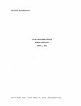
vi
.s
.. '"
!; .
!
. \:~:- ..... ~ ., ..... -~ ...
r---""----
~I
~-/.'
seA MODE
WINDOW
I
c•
-..:;
TRUE
START_
,..
>
OUTPUTS
TRUE
smp
·G'~·.;~u ..
seA
OUTPUT
.C@.
TPHe
OUTPUT
t@-93
."\
___I
~
-
<
;-,,:-
It
"'~
NORMAL
MODE
IN
I
OUT
STOP INHIBIT
MONITOR
DELAY
0.1·1.0,.s
®
-~
d~
.. -
•
•
1
•
ORTEC 467
TIME TO PULSE HEIGHT CONVERTER AND SCA MANUAL
1. DESCRIPTION
1.1. PURPOSE AND FEATURES
The ORTEC 467 Time to Pulse Height Converter and Single
Channel Analyzer (TPHC/SCA) measures the time interval
between the leading edge of logic pulses furnished to its
start and stop inputs and generates an analog output pulse
that is proportional to the measured time through the
TPHC output. The TPHC output pulses are appropriate for
multichannel analysis to obtain timing spectra. They are
also connected internally to the single channel analyzer to
generate an SCA output .logic pulse for each TPHC pulse
with a peak amplitude within the adjusted single channel
limits.
.
•
There are 15' full-scale time ranges that can be switchselected with the 467, from 50 ns through 80 ps. Each
TPHC output pulse has a peak amplitude that is proportional to the ratio of the measured time interval to the
selected full-scale interval, and the range of these pulses is 0
through +10 V.
The 467 is an extremely accurate and versatile instrument.
It is composed of a very stable gated time to pulse height
converter, a low-droop stretcher, a strobed TPHC output,
and a single channel analyzer that can be operated in either
a normal or window mode.
The integrated assembly, in a NIM-standard double-width
module, combines excellent time resolution over a broad
dynamic range with excellent temperature stabilitv and
linearity. It is de-coupled throughout to prevent pileup and
count-rate distortion.
1.2. OPERATION
Start-to-stop time conversion is accomplished only after a
valid start has been identified and after a stop pulse has
arrived within the selected time range. The start input is
disabled during the busy interval to prohibit pileup; the
stop input is disabled after the first accepted stop signal.
Unwanted stop signals that Occur immediately after a start
opened by either an internal or an external strobe. The
internal strobe can be obtained from either the start or the
stop input pulse, and in either case occurs automatically at
a selected delay following the reference. An external strobe
can be used for a prompt output at the strobe time
provided that a time measurement has been completed and
reset has not occurred. A rear panel switch can select either
5 or 120 !JS after stop for an automatic reset if no strobe
has been furnished. If reset occurs before a strobe, no
TPHC output signal is available. There are two other
sources for reset:. one occurs if the start-to-stop time
interval exceeds the range that is selected and the other
occurs as a result of an input pulse through the Inhibit/
Reset Logic Input connector on the front panel. The
normal setting for the rear panel switch is 120 ps;the 5-!JS
setting should be used only if the stoc-strobe mode is used
and the delay is adjusted to minimum, or if the externalstrobe mode is used and the strobe will be furnished within
the selected interval.
The peak amplitude of the TPHC signal is sampled by the
SCA at the time of a true-stop input. If the amplitude is
within the adjusted acceptance range of the SCA, an SCA
logic output is generated. The width of the SCA output is
from the stop input until the subsequent reset. Since this
output occurs before the TPHC signal is used to generate its
analog output, the SCA output can be used to inhibit a
TPHC output, unless the analog signal is within the SCA
window, and to thus limit the range of a timing spectrum as
it is stored in the multichannel analyzer.
The single channel analyzer has a lower level discriminator
that can be adjusted through the full linear range of the
TPHC signals from 0 through 10 V. The range for its
upper-level discriminator is also 0 through 10 V, but the
zero reference point for the ULD must be selected on the
rear panel with the Window/Normal switch. When the
switch is set at Window, the zero reference for the ULD is
the adjusted setting of the LLD control. When the switch is
set at Normal, the zero reference for the ULD is ground
zero and is equal to the LLD zero point.
input, such as those in linear accelerator applications, for
example, can be rejected by a Stop Inhibit Mode switch and
a circuit that. is time-adjustable from 0.1 to 1.0 !JS. An
inhibit/reset circuit also permits the operator to abort and
cancel a measurement after a true start has been recognized.
•
The input gate for the start circuit can be operated in either
an anticoincidence or a coincidence mode.
Time ranges may be switch-selected for full-scale intervals
from 50 ns to 80 !JS. Each time measurement is analoqstored in a low-loss stretcher amplifier until a linear gate is
1.3.
LOGIC
An input can be accepted through the Start Input connector on the front panel unless the 467 is busy processing a
previous set of information or the response is inhibited by a
gate input condition. The acceptance of a start input is
essential in order to initiate a response in the 467. When a
start input is accepted, a positive logic signal is available
through the rear panel True Start Output connector and is
continued until the leading edge of a subsequent reset. The
2
reset can be caused by a TPHC output, by the sensing of an
overrange condition, or by an inhibit/reset signal through
the front panel BNC. The true-start signal permits the
internal circuits to start measuring a time interval and
enables the stop input circuit.
The Stop Input BNC can accept an input signal after it has
been enabled by the true-start condition. It may be enabled
immediately at true start, or the rear panel Stop inhibit
Mode switch can be set at In and there will be a delay from
true start before the stop signal can be accepted; the delay
range is 0.1 through 1.0 jJS. When a stop input signal is
accepted, this indicates that an interval has been measured
and its analog equivalent is stored and available. A signal is"
furnished through the true-stop output that continues until
the leading edge of a subsequent reset. If no stop input is
accepted before an overrange condition is sensed or before
an inhibit/reset input is furnished, the measurement will be
aborted and no output signals for either SCA or TPHC will
be generated.
At the true-stop time the SCA is enabled to sample the
peak amplitude of the stored timing signal and to determine
whether its peak amplitude is within the sinqle-channel
acceptance range. If the SCA responds, it generates an SCA
output that goes high about 600 ns after the leading edge of
the true stop and this signal continues until the trailing edge
of the subsequent reset. If the SCA does not respond
(because the amplitude is either less than the LLD or
greater than the ULDI. no SCA output is generated.
The front panel SCA Inhibit switch determines whether the
SCA response is essential in order to generate a TPHC
output. If the switch is set at In, -a TPHC output is
generated only if the SCA has responded. If the switch is
set at Out, the generation of the TPHC output is independ·
ent of the SCA response.
The TPHC output must be strobed. The source of t h e .
strobe can be switch-selected from the true-start or truestop signal or from an external signal. If true start is
selected as the reference, the strobe occurs after a fixed
delay that is selected by the Multiplier switch so that it will
accommodate the maximum range time; if the switch is set
at Xl, the delay is 2 jJS; for the Xl0 setting, the delay is 10
jJS; and for the Xl 00 setting, the delay is 100 jJS. If true
stop is selected as the reference, the strobe occurs after a
delay that "has been adjusted with the front panel TPHC
Output Delay control, 1 to 10 jJS after the leading edge of
the true-stop signal. If the Strobe Sync switch is set at Ext,
a signal must be furnished through the Strobe Ext BNC
connector to strobe the output promptly.
The reset interval is 5 jJS and no output can be strobed after
the leading edge of the reset pulse. There should be no
interference if the Strobe" Reset switch is set at 120 jJS
unless external strobe is being used and the strobe input
pulse does not arrive within the interval before reset. Reset
can occur as the result of the completion of a read interval
in which the TPHC signal is furnished as an output, or of an
overrange indication where no significant peak amplitude is
available, or of an inhibit/reset input that cancels the cycle
at its leading edge and inhibits further response by the 467.
The principal purpose for the automatic reset Is to furnish
this function if external strobe is being used and the input.
pulse is not furnished. If reset occurs for any reason befor.e
the TPHC output is completed, the TPHC output Width IS
reduced by the reset.
A busy output starts at the leading edge of the true-start
output and continues until" the trailing edge of the
subsequent reset. This can be used to control external
equipment by indicating each interval during which no new
start input can be accepted.
2. SPECIFICATIONS
2.1. PERFORMANCE
Time to Pulse Height Converter
Time Resolution <10 ps (10- 11 sl FWHM On 50- and
100·ns ranges; <0.01 % FWHM of full range for all other
ranges.
Temperature Instability <±10 pstc for
<±O.O 15%t C for higher ranges.
5O·ns range;
Differential Nonlinearity <±2% from 10 ns through full
range for 5O·ns range; <±2% from 5% range to full range for
all higher ranges.
Integral Nonlinearity <±0.1% from 10 ns through full
range for Su-ns range; <±0.1% from 5% range to full range
for all higher ranges.
Single Channel Analyzer
Ternperature Instability
ULD, <"'+0.01 %tC. LLD, <±O.Ol%tC.
•
Nonlinearity Effectively determined by the to-turn potentiometers. ULD, <±0.5% over 10·V range. LLD, <±0.5%
over 10-V range.
3
•
2.2.
CONTROLS
Range usee Switch-selectable 15·range choices of .05. 0.1.
0.2.0.4 or 0.8 J1S multiplied by Xl , X10, or Xl00; the Xl
position can be internally modified to be Xl000 to extend
time range capability to 800 J1S.
Multiplier Front panel 3·position selector switch; settings
select multiple factors for the selected time ranges of Xl,
Xl0, and Xl00, resulting in 15 time ranges from 50 ns to
80 J1S.
Stop Inhibit Mode Rear panel 2-position slide switch:
In Rejects stop pulses that occur within 100 ns to within 1
J1S (adjustable by the Stop Inhibit Delay control) after a
true-start pulse.
Out In this positionswitch does not affect the operation
of the instrument.
Stop Inhibit Delay A 20·turn trim potentiometer mounted
on the rear panel allows the stop inhibit period to be
adjusted from -lOOns to -1 J1S after a true-start pulse.
2.3. INPUTS
TPHC Output Delay Front panel 10-turn screwdriver
potentiometer adjusts the output delay from the stop input
to the internal stop strobe; range, <1 J1S to >10 J1S.
Anti Coine/Coine Front panel slide switch selects either
coincidence or anticoincidence logic for gating the start
input circuit.
SCA ULD Front panel 10·turn potentiometer determines
the window width or the upper-level discriminator setting;
range, 0 to 10 V.
SCA LLD Front panel 10·turn potentiometer adjustable
from 0 to 10 V.
•
SCA Inhibit Front panel slide switch.
In In this position the TPHC output pulse is available only
if the output level falls within the SCA window.
Out In this position the switch has no effect on t~e TPHC
output.
DC Adj 20-turn potentiometer to adjust the dc level over
the range ±O.5 V.
Strobe Sync Rear panel 3·position slide switch for selecting one of three modes:
Int Start In this position the information is strobed out
-2 J1S after the start pulse when the Multiplier switch is in
the Xl position, -lOlls in the X10 position, and-100lls
in the Xl00 position.
Ext In this position a positive pulse fed into the Strobe
Ext COnnector will strobe the information to the output if
the strobe pulse has a magnitude of +3 V or larger.
Int Stop In this position the information is strobed out 1
to 10 J1S (adjustable by the TPHC Output Delay control)
after a true-stop pulse.
Start Input Front panel BNC connector.
Amplitude -250 mV minimum; protected to ±loo V.
Zin = 5OU. de-coupled.
Rise Time No limit. but rise time should be as short as
possible to provide maximum accuracy.
Pulse Width 3 ns a.t -250 mY; maximum limit, -4 J1S.
Stop Input Specifications same as for the Start Input.
Gate Logic Input
<+2 V; logic 1.
Gate signal must
overlap the start
coupled.
Front panel BNC connector. Logic 0,
>+2 V; input protected to ±loo V.
occur 10 ns before the start and must
input pulse. Impedance, -1 kU, de-
Inhibit/Reset Logic Input Front panel BNC connector.
Amplitude of >4 V resets circuit at any point in the cycle
and inhibits start pulses for the duration of the pulse: input
protected to +12 V.
Strobe Ext Rear panel BNC connector.
Amplitude >+2 V; protected to >±25 V.
Rise Time No limit. .
Pulse Width 10 ns minimum; .......41ls maximum.
Impedance I kU de-coupled.
Control Outputs Prompt with strobe input.
2.4.
OUTPUTS
TPHC Outputs Front and rear panel BNC connectors.
100% protected from short circuit and excessive duty cycle.
Unipolar 0 to +10 V linear; <500 ns rise time.
Width Internally adjustable from -1.0 to 2.5 J1S.
Output Timing Prompt with either internal or external
strobe.
Impedance <lU on front oanetand 93U On rear panel,
de-coupled.
Strobe Reset Rear panel 2·posi tion switch that allows the
converter to be reset either 5 J1S or 120 J1S after a true-stop
pulse if a strobe pulse has not been received.
•
SCA Mode Rear panel 2,poSition slide switch:
Normal Allows independent use of upper level discriminator and lower level discriminator.
Window ULD setting is added to LLD setting when switch
is in this position.
Output de Level Adjustable from 0 to ±0.5 V dc with
front panel DC Adj screwdriver control.
SCA Outputs Front and rear panel BNC connectors. 100%
protected from short circuit and excessive duty cycle.
Ampiitude =+4 V on positive logic if TPHC pulse is in the
LLD-ULD window and 0 V if TPHC is not in the window.
Output Timing Pulse begins -600 ns after a valid stop
pulse and continues until TPHC resets.
Impedance IOU, de-coupled.
-L
\
4
True Start Output Rear panel BNC COnnector provides a
positive logic timing output to indicate the interval from an
accepted start input signal until reset.
Rise Time <100 ns.
Output Width The interval from the start input until reset
time, which can occur at strobe time, overrange, or 120
us
after stop signal.
. Impedance <lOn, de-coupled,
True Stop Output Rear panel BNC connector provides a
positive 4-V pulse to indicate valid stop and the interval
from an accepted stop input signal until reset occurs.
Rise Time <100 ns,
Impedance ""lOn, de-coupled.
Output Width The interval from the stop input until reset
Stop Inhibit Monitor Rear panel BNC connector provides.
a positive 3.5-V pulse to indicate the time period during
which stop signals are inhibited.
Rise Time <100 ns.
Output Width Variable from 100 ns to >1.0 us with Stop
Inhibit Delay trim potentiometer, beginning when a truestart pulse is received. Stop pulses are rejected until this
pulse returns to the baseline if the Stop Inhibit Mode
switch is in the In position.
Impedance -lOn, de-coupled,
2.5. ELECTRICAL AND MECHANICAL
Power Required
time.
TPHC Busy Output Via rear panel BNC connector to
indicate the total time that the 467 is involved in a
conversion; amplitude, +4 V; tr <100 ns: Zo, lOn,
de-coupled. Output width is equal to the interval from the
start input to 5 us after reset.
+24 V, 165 mA;
+12 V, 320 mA;
-24 V,120mA;
-12 V, 140 mAo
Dimensions NIM·standard double-width module (2.70 in.
wide by 8.714 in. high) per TID·20893.
3. INSTALLATION
3.1. GENERAL
An ORTEC 401/402 Series Bin and Power Supply, or
equal, in which the 467 will be installed, is intended for
rack mounting. If vacuum tube equipment is operated in
the same rack, there must be sufficient cool air circulating
to prevent localized heating of the all-transistor circuits in
the 467 and in the other modules in the Bin and Power
Supply. Rack-mounted equipment subjected to the temperatures in vacuum tube equipment can exceed the maximum
for which th'e transistorized circuits are designed unless this
precaution is taken. The 467 should not be subjected to
temperatures in excess of 120°F (50°Cl.
3.3,
CONNECTION INTO A SYSTEM
•
The 467 can accept both start and stop pulses from
discriminators that furnish NIM-standard fast negative logic
signals or from the timing output of a photomultiplier tube
base. Typical ORTEC instruments that provide compatible
signais are the 416A, 403A, 473, and 260 discriminators
and the 265, 269, 270, and 271 Photomultiplier Tube
Bases. The start and stop inputs will properly terminate
50n cable, and this type is recommended to ensure proper
termination of the signals.
No input or output connectors need be terminated when
they are not in use.
3.2. CONNECTION TO POWER
The
467 is designed per TID·20893 and accepts its
operating power requirements through a mating power
connector when it is installed in an ORTEC 401/402 Series
Bin and Power Supply. As a safety precaution, atwavs turn
In any experiment in which it is reasonable to assume that
the count rates for start and stop will be equal or nearly so,
use the signal furnished from the origin of events into the
start input and the signal furnished from the response into
the stop input. The 467 will then measure the time
off the power for the Bin before inserting or removing any
difference T from origin to response and furnish an output
modules. If all the modules installed in the Bin are ORTEC
400 and/or 700 Series instruments. there will be no
amplitude that is some fraction of the selected full-scale
amplitude, proportional to the ratio of T to the selected
full-scale time range.
overload on any portion of the Power Supply. However, if
any modules not aesigned by ORTEC are included in the
Bin, this protection may not be effective; monitor the de
voltages at the test points on the control panel of the Bin
after all modules have been installed and the power is
In any experiment in which the two count rates differ.
noticeably, such as one in which fewer responses than event
origins can be expected, use the lower count rate as the
turned on, in order to determine that none of the four
start input to the 467. This assures that the 467 dead time
power levels have been reduced by an overload.
will be minimized. because it analyzes the time difference
5
only after a start signal is accepted. When the response is
used as a start signal, furnish the signals from the origin of
events through a delay line into the stop input, and adjust
the delay to match the selected full-scale time of the 467.
At each start input signal the 467 will analyze the time
until its related origin signal is furnished to the stop input.
The time measured is then delay time minus T, and
produces a so-celled inverted time spectrum. The purpose
for this type of system connection is to reduce the number
of conversions and the corresponding dead time during the
experiment. For each signal accepted through the start
•
input there must be a conversion, but for each signal
through the stop input there need not be a conversion. For
each start signal that is not followed by a stop signal within
the selected time full range, the converter measures a time
equal to the total range, even though no output pulse is
generated.
3.4,
LINEAR OUTPUT SIGNAL CONNECTIONS
AND TERMINATING IMPEDANCE
The source impedance of the standard TPHC output, with
the O· to 10·V linear range, is about ln through the
connector on the front panel and g3n through the
connector on the rear panel.
For the front panel circuit the interconnection to other
•
terminated. When longer cabfe lengths are required for
transfer of a linear signal, the cable should be terminated in
a resistive load equal to the cable impedance to prevent
reflections and oscillations in the cable. Oscillation suppressian can be effected by either- a series termination at the
sending end of the cable or by a shunt termination at the
receiving end. For convenience a BNC tee can usually
accommodate both the cable and a mating terminator at
the input of the receiving instrument. These units are
available commercially, including BNC" terminators with
nominal values of 50, 100, and lOOOn. ORTEC stocks a
limited quantity of all but t~e lOOOn terminators for your
convenience, as listed below:
BNC Tee Connector
50n Terminator
lOOn Terminator
ORTEC C·29
ORTEC C·28
ORTEC C·27
When a shunt termination at the receiving end of the cable"
is impractical, consider series termination at the sending
end. For a series termination the full signal amplitude span
is available at the receiving end only if the input impedance
is many times the characteristic impedance of the cable.
For series termination install the correct resistance between
the actual amplifier output, on the etched circuit board,
and the output connector. Effectively, the terminating
modules does not usually require any special considera-
resistance is in series wi th the input impedance of the
receiving instrument, and may result in some loss in signal
tions, especially if the interconnecting cable is shorter than
4 It in length, Paralleling several loads on a single output
will still not reduce the O· to lO·V signal span significantly
unlessthe combined load is less than lOOn.
amplitude. For example, if the series terminator is 9311 and
the driven load is 900n, the available signal span will be
only about 90% of the maximum signal amplitude for each
pulse. The termination of a 93n cable in a 93Q load will
cause a 50%
The rear panel TPHC output circuit is designed for use of
93n cable to transfer the signals into a measuring' circuit
that has an input impedance of at least lOOOn. With this
series Impedance-matched circuit connection, there will
usually not be any interference with the signal. If oscillations should occur, it will be necessary to provide an
additional shunt termination of lOOn in parallel with the
loss for the signal.
3.5.
LOGIC SIGNAL CONNE~TlONS
The start and stop input circuits accept NIM·standard fast
negative pulses. Each of these input circuits is designed with
a 50n input impedance and is intended as the proper
termination for the signals. furnished through 50n cables.
input circuit of the receiving instrument, but this will result
in about a 50% loss of signal amplitude.
As with any analog instrument, asci llations may be observed occasionally when un terminated lengths of cable are
used. Short cable lengths (up to 4 ft)
4.
•
4.1.
need not be
OPERATING INSTRUCTIONS
TIME TO PULSE HEIGHT
CONVERSION
There are seven front panel controls on the 467. Of these,
four are directly associated. with
I mpedance considerations for each of the remaining logic
inputs and output for the 467 are noncritical and 9311
cable is usually used. They can be terminated with lOOn to
prevent ringing if the signal is used to drive a highimpedance load.
the conversion of a
star t-to-stop interval into an analog equivalent TPHC
output pulse. These controls are Range usee, Multiplier,
TPHC Output Delay, and Anti Caine/Caine. If the SCA
Inhibit switch is set at In, this also affects the generation of
a TPHC output.
6
The Range usee and Multiplier switches determine the
full-scale limit for time conversion. Any of 15 combinations'
through the Gate Logic Input connector when start signals
are to be accepted.
•
may be selected as follows:
Switch Sattings
Range
0.05
0.1
0.2
Multiplier
Xl
Xl
Xl
Xl '
Full-Scale
Time Limit
50 ns .
100 ns
200ns
400 ns
0.4
0.05
0.8
0.1
0.2
0.4
X10
Xl0
1 I's
21'S
41'S
0.05
0.8
0.1
X100
X10
X100
51'S
81'S
10 us
0.2
0.4
0.8
X100
X100
X100
20I'S
40 IJS
80 IJS
X10
Xl
X10
500 ns
800ns
If a signal is furnished through the Inhibit/Reset Connector
on the front panel, any time measurement that may be in
process will be aborted and no new measurement can begin
until the inhibit/reset signal is removed. To be effective: the
inhibit/reset signal must precede an output strobe time:
The rear panel Strobe Sync switch selects the source for the
strobe signal for the TPHC output. When the switch is set at
Int Start. the strobe is generated by a delayed true-start
signal and the delay is fixed at a time that is longer than the
selected Iull-ranqe time. When the switch is set at Int Stop,
the strobe is generated by a delayed true-step signal and the
delay is adjusted by the TPHC Output Delay control on the
front panel within the range of 1 to 10 IJS. When the switch
is set at Ext, an input pulse must be furnished through the
adjacent 8NC connector and the TPHC output signal is
strobed promptly at the external signal time.
The timing of an external strobe input signal must be
within the switch-selected interval, 5 or 1201's, after the
true-stop pulse for the measurement. If the strobe is
furnished prior to stop, the signal is not accepted. In the
case of a strobe pulse failing to arrive within the selected
interval after stop, the 467 will have been automatically
reset internally;
so
there is no available output and t h e .
strobe signal is ignored. If the 467 is to be used as a
For 'example. with the Range switch set at .0.05 and the
Multiplier switch at Xl00, the full-scale time range is 51JS.
Any stop inout signal that Occurs wi thin 5 us aher a
true-start signal will initiate the gating of an output pulse
through both TPHC Output connectors. The output pulse
will not be furnished through these connectors unless it is
strobed. The SHobe condition is selected by a rear panel
switch and can be based on the time of the true-start signal.
delayed by an amount 'of time greater than the selected
full-scale time, or by the stop signal, delayed by an amount
of time adjusted with the front panel TPHC Output Delay
control. or by an external strobe input signal. When the
output does occur, its peak amplitude will be proportional
to the ratio of the measured star t-to-stop interval to the
selected full-scale time, in a O· to 10·V range.
stretcher or buffer storage of the analog output for more
than 120 J.1s, a simple modification can increase this time
limit; see Section 6.5.
By the addition of four jumpers in the 461 circuit the Xl
set ting of the Multiplier switch can be replaced by a X1000
setting. If these jumpers are added, as described in Section
6.4, the minimum time range setting is 500 ns and the
maximum range is ~OO J.1s.
In any application of the 467 in which stop signals occur
immediately following a true start but are to be ignored. in
favor of time measurements, to stop siqnals that occur later,
the rear panel Stop Inhibit circuit can be used. With the
Mode switch set at In, the adjacent screwdriver control can
be adjusted for a delay of 0.1 to 1.0 I'S and all stop Signals
Internal logic. eliminates any pulse ambiguity. No output
pulse is furnished unless a stop signal is accepted within the
selected tull-ranqe time. A stop signal is not effective unless
it is preceded by a true-star t signal. For further logical
control either a coincidence or anticoincidence mode can
be selected for gating control of the start input circuit. To
eliminate gating for the start input, set the Gate switch at
Anti Caine and leave the gate input circuit without any
connection. When the same switch setting is used and an
input signal is furnished, start signals are not accepted when
the gate signal is +2 V or more.
For coincidence gating of the start input circuit. set the
Gate switch at Coine and furnish a signal of +2 V or more
\
are ignored that occur within the adjusted delay time
following a true-start signal. The adjusted time delay can be
monitored through the rear panel Monitor connector to
measure the duration of the delay signal that occurs at each
true-start-input time.
4.2. SINGLE CHANNEL ANALYSIS
l_
The single channel analyzer portion of the 467 measures
the peak amplitude of each a.nalog !PH.C ~ulse as soon as
is formed. If the peak amplitude IS within the lower an
uoper limits that are set with the LLO and ULD controls on
the front panel, an SCA output signal is generated after a
400-ns propagation time. The signal can be used to control
7
•
the subsequent generation of a TPHC output if the front
panel SCA Inhibit switch is set at In. Under this condition
the SCA must generate an output in order to permit the
generation of a TPHC output at its strobe time, and this can
limit the range of time signals that are furnished to a
multichannel ·analyzer to generate a spectrum. An independent SCA output signal is furnished through both the
front and rear panel SCA Output BNC connectors for any
external applications that may be desired.
A rear panel switch selects either Window or Normal mode
for the SCA. In the Window mode the acceptance range is
from the LLO setting to the sum of the LLO plus ULO
settings. In toe Normal mode the LLO control and the ULO
control each operates independently .and the acceptance
range is from the LLO setting to the ULO setting; the lILO
setting must alwavs be greater than the LLO setting to
generate an SCA output...
5. CIRCUIT DESCRIPTION
5.1. GENERAL
The circuits for the 467 are shown in schematics
467·0201-S1 and 467'{)301-S1 and in block diagram
467'{)101-B1. All these drawings are included at the back of
the manual.
•
The co mponents that are included in schematic
467-0201-S1 all have reference designation numbers that
are less than 300, and those on the 467'{)301-S1 drawing
have reference designations in the 300 series. The division
of circuits between the two boards on which the components are mounted is indicated in the block diagram.
The nomenclature used to identify the integrated circuit
packages referred to in this manual is defined below for the
example
IC2(10),
where
l'C = integrated circuit,
2 = component number,
(101 = pin number.
Any portion of an IC package can be designated by its
output pin number.
5.2. TPHC CIRCUIT
•
two functions: It drives the true-start-output .circuit (Q5,
06, IC1, and 056) for an external timing signal keyed to an
accepted and valid srar t input, and it switches ttie current
that normally flows through Q12 to 011. While current
flows through Q11, 010 is held at cutoff and a constant
current from Q46 cnarqes the selected ti ming capacitor
linearly; the timing capacitor ·(C6 and possibly C32 or C33)
is selected by the Ranga Multiplier switch, S2. If the Xl
selection is changed to a X1000 selection, C29 and C31 can
also be selected as a part of the timing capacitor. The
voltage to which the selected timing capacitor can be
charged is limited to 3.6 V by Q7.
The start input circuit contains 01, 01, and resistors Rl
through R4, which form a voltage limiter to protect the
base input circuit of 02. A negative input signal of 250 mV
or more, limited at 700 mV, is amplified by 02 and 03 and
causes tunnel diode 03 to switch from its low state (-50
mVI to its high state (-450 mVI. The tunnel diode remains
in the high state until reset is furnished from 051 to trigger
03 back to its low state.
While tunnel diode 03 is in its high state, the current that
normally flows through 05 is switched to 04 to perform
The voltage developed across the timing capacitor is applied
to the input of a stretcher amplifier that includes Q41
through 044. This amplifier has a gain of unity and its
output voltage is obtained from the gaie of Q44B.
If a stop signal is not furnished within the selected time'
range, Schmitt trigger 053 and 054 fires at a timing
capacitor level of about 3 V from a 10-V signal on 037E.
This identifies an overrange condition. The output triggers
the reset circuit, which includes Q48, 049, 051, and Q52.
The reset circuit causes tunnel dicde 03 to return to its low
state without generating a TPHC output pulse.
If
an external stop signal is received prior to the overrange
identification, 046 is switched off and the timing capacitor
receives no further charge. The charge that accumulated on
the ti ming capaci tor between the start and stop input pulses
determines the capacitor's VOltage and therefore the output
voltage.
In the stop input circuit, diode 09 and its associated
resistors form an arnolitude-lirnitinq circuit similar to the
start input circuit. A valid start pulse enables the stop
circuit through 017. The stop pulse is amplified by 018
and 019. If the stop pulse arrives while 011 is enabled. this
diode is driven to its high state to switch the current from
021 through 020. When Q20 conducts, 045 is driven into
conduction and the constant current through Q46 is cut
off. The selected timing capacity is not charged any further
-,
8
and has no discharge path; so it holds the volta je to which
it has been charged.
Switching pair Q21 and Q20 also performs tVIO additional
functions. If the internal stop strobe is useo. a trigger is'
furnished to the read timer, Q24 and 027 through 029. .
This circuit generates a delay of 1 to 1Co J.lS and then
operates gate circuit Q35 and 036. Switchirg pair 021 and
020 also furnishes a strobe to the SCA circt.It through 022
and Q23.
Read timer 027 and 028 performs two fi nctions: It opens
linear gate 036 and triggers reset throuqr 052. Timing for
027 and Q28 is adjusted by R86, and the gate width is
normally set at about 2 J.lS. The linear ga.e is opened during
this period and reset occurs at the enn of the period. At
reset tunnel diode 03 is switched tc its low state and
cannot be switched beck to high again for about 5 J.lS: this
feature prevents pileup. When 03 is r'·set, it forces Dl1 to
its low state through 04, 012, and Q1 7.
Linear gate 036 conducts a current with an amplitude
proportional to the charge stored .n the timing capacity,
and the charge is proportional tc the time between start
and stop input signals. The gatin'J pulse from Q33 causes
035 to conduct to, in turn, cut (Iff 036. The current that
was flowing through 036 is rarouted into GA·l during the
period of the gating pulse. GA-' is a hiqh-qain operational
amplifier that has its gain requla.ad to -1 for positive input
signals and to 0 for negative input signals. The output from
GA·l drives another operational amplifier, GA·2 on the
0301 board, that has a gain of -1 and generates the positive
TPHC output signals.
The TPHC information rmv be strobed out in three
different ways: The strobe pulse can oereferencec inter-
nally to the stop signal, internally to the start signal, or .
externally. In each case a
ole-shot multivibrator is triggered
to generate the gate pulse. In the stop-strobe mode R73 and
R74 with C13 determine the time from the stop pulse until
024 conducts and the one-shot circuit is triggered. The
delay is adjusted from 1 to 10 J.lS by R73 on the front
panel. In the start-strobe mode the true-start signal from
ICH121 triggers a one-shot multivibrator that includes
IC3161. C55, R189, and R191. The period of this one-shot
circuit
is variable
internally and determines the delay
between the start pulse and the strobe pulse. The startstrobe signal drives the gate one-shot that includes lC4,
059, and 026. In t"e external strobe mode a positive pulse
through the Strobe Ext input connector drives the gate
one-shot through 026.
Logic signals corruspondinq to true start, true stop, and
TPHC busy are g',nerated by the circuits that include IC1,
IC2, 056, 057, znd 058. If for any reason a strobe signal is
not received, th" TPHC circuits are reset after 5 or 120 J.lS,
selected by S5, through 033 and the overrange circuit, by
R103, C19, an J C22. For this condition there is no TPHC
output signal.
5,3,
SING LE CHANNEL ANALYZER CIRCUIT
•
There are two discriminator circuits in the SCA. The
lower-level discriminator uses IC304, IC305, and IC306.
The upper-level discriminator uses IC301 , IC302, and
IC303. Both channels obtain their reference voltage from
D301 and the maximum voltage at TP1 and TP2 is adjusted
to ":'5 V with R301 and R316. The TPHC amplitude from
Q37 is divided by R333 and R334, 'and 50% of the TPHC
level is compared in IC303· and IC306 to their reference
levels, determined by the settings of R302 and R317 on the
front panel, and to the setting of rear panel SCA Mode
switch S6.
A signal is obtained from the stop circuit through 023 to
trigger a one-shot that includes IC308, R336, and C352_
The output of the one-shot is used to strobe the lower and
upper comparators. If the TPHC signal exceeds the lower
reference but does not exceed the upper reference, a
positive logic output of 4 V is obtained at Q305 through
IC307, IC30B, and IC309. If the TPHC signal is less than
the lower reference or greater than the upper reference, the
gate circuits in IC309 are not activated and there is no SCA
output.
When switch S6 is set at Window, the tower-level and
upper-level reference voltages are summed at the input of
IC302. For this condition the window is the difference •
between the lower-level adjustment and the sum of both
the lower- and upper-level adjustments within the linear
range limits of th'e SCA.
5.4. AUXILIARY LOGIC
The 467 includes an input gate circuit, a stop inhibit
Circuit, an inhibit-and-reset circuit, and an SeA inhibit
circuit. The function of each of these logic circuits is
defined in Sections 4.1 and 4.2.
The input gate circuit consists of 07,013, Q15, and Q16.
When Gate switch SB is set at Anti Coinc, 013 is saturated
and a negative start input pulse can trigger tunnel diode 03.
If a positive gate input signal is furnished through CN2,
015 conducts and clamps D3 to prevent it from responding. With the Gate switch set at Coinc Q13 clamps D3 and
prevents it from responding except when a positive input is
furnished through CN2.
Stop signals can be inhibited from triggering Dl1 through a
controlled interval following each true start. This function
uses IC3 and IC4. The start signal triggers a one-shot
multivibrator that includes IC3, C56, R 196, and R 197. The
output of IC4 is normally high and is driven low during the
period of the one-shot. If Stop Inhibit switch S7 is set at In,
the positive signal from IC4 clamps Q17 through 016 t o .
prevent response in Dl1. After IC4 returns to low, Q17
conducts and enables Dl1 to accept a stop input pulse. A
positive monitor output is produced through 060 during
the inhibit interval.
9
•
A signal through the Inhibit/Reset connector on the front
panel activates the overrange circuit, 053 and 054, and
resets the TPHC circuit at any time during a cycle. A
positive input through CN6 drives the base of 053 negative
through 055. The reset circuit forces D3 to its low state
and clamps it· until the external signal drops below
approximately 3.5 V. During this period astart signal will
not be accepted.
.
If SCA Inhibit switch S3 is set at In, an SCA output signal
is necessary in order to enable a strobed TPHC output. With
the switch in this position 030 is normally saturated and
blocks the gating signal at 031. A positive SCA output
signal ("SCA OK") cuts off 030 and allows t~e gating
signal to propagate through 031 to the gating circuit.
6. MAINTENANCE
•
6.1. TESTING PERFORMANCE
3. Check the installation for proper mechanical alignment.
The following test procedures are furnished as a guide
during installation and checkout of the 467 TPHC/SCA.
4. Switch on ac 'power and check the dc power voltage
levels at test points on the 402 Power Supply control panel.
Test Equipment The following test equipment is recornmended. Each test procedure refers to this list by the unit
identification "number for the required iternls) of test
equipment. An equivalent unit may be substituted for any
item in the list, providing that it furnishes the function
required for each specific application.
Basic Switch Settings Set the 467 controls as follows:
1. Hewlett-Packard 222A Pulse Generator
2. ORTEC 436 100 MHz Discriminator
3. ORTEC 416A Gate and Delay Generator
Range
Multiplier
ULD
LLD
SCA Inhibit
Logic Input
Strobe Sync
SCA Mode
Strobe Reset
Stop Inhibit Mode
0.051lS
1
10 (fully clockwise)
o
(fully counterclockwise)
Out
Anti Coinc
Int Stop
Normal
120 IlS
Out
4. ORTEC 425 Nanosecond Delay
5. Photomultiplier tube with scintillator and radiation
source
Conversion Tests Use the typical test set-up shown in Fig.
6.1 and supply a start and stop pair of input signals with
known time difference into the 467. Observe the TPHC
output. Then use the following procedures:
6. ORTEC 403A Time Pickoff Control
1. Adjust the delay for the stop input to 25 or 30
ns more
7. ORTEC 449 Log/Lin Ratemeter
than the basic 13 ns required for a minimum response.
8. Tektronix Type 5B5 Oscilloscope
2. Check to see that the full-scale time range is 0.05/JS X
1. or 50 ns.
9. ORTEC 6240 Multichannel Analyzer
PULS'
10. ORTEC 414A Fast Coincidence
GENERATOR
'I>
,.-
FANOUT
121
Ot
131.
Preliminary Procedures Take the following preliminary
steps when the 467 is installed:
•
,EU
.. -j 1-:=
N.,.
ORTEe
Output
1. Check the module visually for possible damage.
2. With the power turned off, install the 467 into a
NIM·standard Bin and Power Supply such as one of the
ORTEC 401/402 Series.
n"::"
Inpvt
11. ORTEC 444 Gated Biased Amplifier
DELAY
131
U
'"
OSCILLO~
I--
SCOPE
lSI
S'opl."",
:0011'<1
Fig. 6..1. Test System for Checking Conversion.
I(
;J/ AAI
Iv
I'
_
-
f3 / /J
W1RJ
N(J
, I
•
BIN/MODULE CONNECTOR PIN ASSIGNMENTS
FOR AEC STANDARD NUCLEAR INSTRUMENT MODULES
PER TID-20893
Pin
1
2
3
4
5
6
7
8
9
'10
'11
12
13
14
15
'16
'17
18
19
20
21
22
Function
+3 volts
-3 volts
Spare Bus
Reserved Bus
Coaxial
Coaxial
Coaxial
200 volts de
Spare
+6 volts
-u volts
Pin
Spare
Spare
23
24
25
26
27
'28
'29
30
31
32
'33
'34
.... 35
**36
Re'served
""*37
Reserved Bus
+12 volts
-12 volts
Spare Bus
Reserved Bus
Spare
Spare
38
39
40
'41
'42
G
Function
Reserved
Reserved
Reserved
Spare
..spare
+24 volts
-24 volts
Spare Bus
Spare
Spare
115 volts ae (Hot)
Power Return Ground
Reset is caler)
Gate
Reset (Auxiliary)
Coaxial
Coaxial
Coaxial
115 volts ac (Neut.)
High Quality Ground
•
Ground Guide Pin
Reserved
Pins marked (.) are installed and wired in ORTEC 401 A and 4018 Modular System Bins.
Pins marked {"} and (. -) are installed and wired in EG&G/ORTEC~HEP M250/N and M350/N NIMBINS.
•