1
TK-8160H
CIRCUIT DESCRIPTION
■ Key Matrix Circuit
Control Circuit
1)
2)
3)
4)
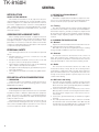
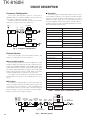
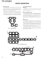
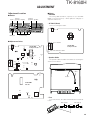
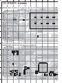
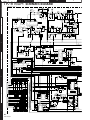
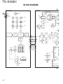
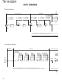
The CPU carries out the following tasks:
Controls the WIDE, NARROW, TX/RX outputs.
Controls the AQUA IC (IC241).
Controls the PLL (IC401).
Controls the D/A converter (IC201) and adjusts the volume, modulation and transmission power.
CK
DT
LD
IC201
D/A
converter
IC101
CPU
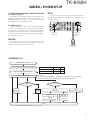
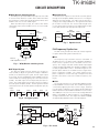
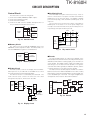
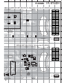
The TK-8160H front panel has function keys. Each of
them is connected to a cross point of a matrix of the KMI1 to
KMO3 ports of the IC1 LCD driver. The KMO1 to KMO3
ports are always high, while the KMI1 to KMI3 ports are always low.
The microprocessor monitors the status of the KMI1 to
KMO3 ports. If the state of one of the ports changes, the
microprocessor assumes that the key at the matrix point corresponding to that port has been pressed.
IC401
PLL
PLLE
Fig. 10 Control circuit
IC1
LCD
driver
■ Memory Circuit
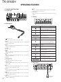
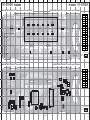
The transceiver has an 64k-bit EEPROM (IC81). The
EEPROM contains adjustment data. The CPU (IC101) controls the EEPROM through three serial data lines.
KMI1
KMI2
KMI3
VOL
UP
CH
UP
A
VOL
DN
CH
DN
<B
C>
S
KMO3
KMO2
KMO1
Fig. 13 Key matrix circuit
EEPCK
IC101
CPU
Fig. 11
EEPDT
EEPWP
IC81
EEPROM
■ Encode
Memory circuit
■ Display Circuit
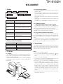
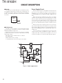
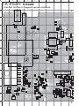
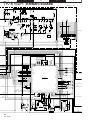
The CPU (IC101) controls the display LCD and LEDs.
When power is on, the CPU will use the MBL line to control
the LCD illumination and key backlight LEDs.
The dimmer function is controlled by the switch Q1. The
LCD controller (IC1) controls the functions of the LCD
through the DO, CE, CL, DI lines from the CPU.
IC101
CPU
CE
CL
DI
DO
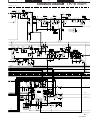
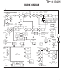
The QT and DQT signals are output from QT/DQT of the
CPU (IC101) and summed with the external pin DI line by the
AQUA IC (IC241) and the resulting signal goes to the D/A converter (IC201). The DTMF signal is output from DTMF of the
CPU and goes to the D/A converter (IC201). The signal is
summed with a MIC signal by the AQUA IC (IC241), and the
resulting signal goes to the D/A converter (IC201).
The D/A converter (IC201) adjusts the MO level and the
balance between the MO and QT/DQT levels. Part of a QT/
DQT signal is summed with MO and the resulting signal goes
to the VCOMOD pin of the VCO. This signal is applied to a
varicap diode in the VCO for direct FM modulation.
IC241
AQUA
IC
QT/DQT
IC1
LCD
driver
Q1
SW
BRI
BL
Q4
SW
Q3
SW
Fig. 12
Q2
SW
IC101
CPU
DI
DTMF
D7~D18
LCD
illumination
IC201
D/A
IC241
AQUA
IC
TCXO
MOD X401
TCXO
IC201
D/A
IC401
PLL
VCO
VCO
MOD
HT
Fig. 14 Encode
D1~D6
Key backlit
Display circuit
15