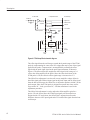
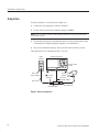
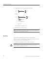
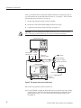
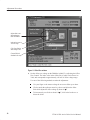
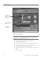
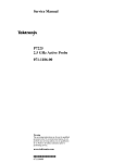
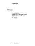
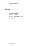
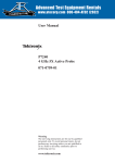
1
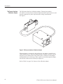
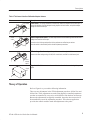
Service Manual
P7240 4 GHz
Active Probe
071-1056-00
Warning
The servicing instructions are for use by qualified
personnel only. To avoid personal injury, do not
perform any servicing unless you are qualified to
do so. Refer to all safety summaries prior to
performing service.
www.tektronix.com
*P071105600*
071105600
©
Copyright Tektronix, Inc. All rights reserved. Licensed software products are owned by Tektronix or its suppliers and
are protected by United States copyright laws and international treaty provisions.
Use, duplication, or disclosure by the Government is subject to restrictions as set forth in subparagraph (c)(1)(ii) of the
Rights in Technical Data and Computer Software clause at DFARS 252.227-7013, or subparagraphs (c)(1) and (2) of the
Commercial Computer Software – Restricted Rights clause at FAR 52.227-19, as applicable.
Tektronix products are covered by U.S. and foreign patents, issued and pending. Information in this publication supercedes
that in all previously published material. Specifications and price change privileges reserved.
Tektronix, Inc., P.O. Box 500, Beaverton, OR 97077
TEKTRONIX, TEK, TekConnect, and KlipChip are registered trademarks of Tektronix, Inc.
General Safety Summary
Review the following safety precautions to avoid injury and prevent damage to
this product or any products connected to it. To avoid potential hazards, use this
product only as specified.
Only qualified personnel should perform service procedures.
Do Not Service Alone. Do not perform internal service or adjustments of this
product unless another person capable of rendering first aid and resuscitation is
present.
While using this product, you may need to access other parts of the system. Read
the General Safety Summary in other system manuals for warnings and cautions
related to operating the system.
To Avoid Fire or
Personal Injury
Connect and Disconnect Properly. Do not connect or disconnect probes or test
leads while they are connected to a voltage source.
Observe All Terminal Ratings. To avoid fire or shock hazard, observe all ratings
and markings on the product. Consult the product manual for further ratings
information before making connections to the product.
Do not apply a potential to any terminal, including the common terminal, that
exceeds the maximum rating of that terminal.
Do Not Operate Without Covers. Do not operate this product with covers or panels
removed.
Do Not Operate With Suspected Failures. If you suspect there is damage to this
product, have it inspected by qualified service personnel.
Do Not Operate in Wet/Damp Conditions.
Do Not Operate in an Explosive Atmosphere.
Keep Product Surfaces Clean and Dry.
Provide Proper Ventilation. Refer to the manual’s installation instructions for
details on installing the product so it has proper ventilation.
P7240 4 GHz Active Probe Service Manual
i
General Safety Summary
Symbols and Terms
Terms in this Manual. These terms may appear in this manual:
WARNING. Warning statements identify conditions or practices that could result
in injury or loss of life.
CAUTION. Caution statements identify conditions or practices that could result in
damage to this product or other property.
Terms on the Product. These terms may appear on the product:
DANGER indicates an injury hazard immediately accessible as you read the
marking.
WARNING indicates an injury hazard not immediately accessible as you read the
marking.
CAUTION indicates a hazard to property including the product.
Symbols on the Product. The following symbols may appear on the product:
CAUTION
Refer to Manual
ii
WARNING
High Voltage
Double
Insulated
Protective Ground
(Earth) Terminal
Not suitable for
connection to
the public telecommunications network
P7240 4 GHz Active Probe Service Manual
Preface
This is the service manual for the P7240 4 GHz Active Probe. Read this preface
to learn how this manual is structured and where you can find other information
related to servicing this product.
Manual Structure
This manual contains three sections – Description, Performance Verification,
and Adjustment Procedures, and is intended to be used by qualified service
personnel. Replaceable parts are limited to accessories and adapters, and are
described in the Instruction Manual that is shipped with the probe.
Be sure to read the introductions to all procedures. These introductions provide
important information needed to do the service correctly, safely, and efficiently.
Related Documentation
The probe is shipped with the following manual:
H P7240 4 GHz Active Probe Instruction Manual. Tektronix part number
071-0759-XX.
P7240 4 GHz Active Probe Service Manual
iii
Preface
Contacting Tektronix
Phone
1-800-833-9200*
Address
Tektronix, Inc.
Department or name (if known)
14200 SW Karl Braun Drive
P.O. Box 500
Beaverton, OR 97077
USA
Web site
www.tektronix.com
Sales support
1-800-833-9200, select option 1*
Service support
1-800-833-9200, select option 2*
Technical support
Email: [email protected]
1-800-833-9200, select option 3*
6:00 a.m. – 5:00 p.m. Pacific time
*
iv
This phone number is toll free in North America. After office hours, please leave a
voice mail message.
Outside North America, contact a Tektronix sales office or distributor; see the
Tektronix web site for a list of offices.
P7240 4 GHz Active Probe Service Manual
Description
This document describes the Performance Verification and Adjustment Procedures for the P7240 4 GHz Probe. There are no user-replaceable parts inside the
probe. If the probe fails the performance verification procedure, and adjusting the
probe cannot compensate for the failure, contact your Tektronix service center.
Performance Verification
Use the performance verification procedures to verify the warranted specifications of the P7240 probe. The recommended calibration interval is one year. No
software is required to complete a performance verification of the probe.
The performance verification procedures check the following specifications:
H Output zero
H DC attenuation accuracy
H Rise time
Adjustments
The P7240 probe has two electronically-adjusted controls that rarely need
adjusting unless a performance verification yields a specification that is out of
tolerance, or the probe fails an oscilloscope probe calibration utility.
If you must make adjustments to the probe, you need the TekConnect Adjustment Software for the P7240 4 GHz Probe. Refer to Equipment Setup in the
Adjustment Procedures, step 7, for instructions on finding and loading the
adjustment software on your instrument.
The adjustment procedures describe the following adjustments for the probe:
H Offset zero
H Offset gain
P7240 4 GHz Active Probe Service Manual
1
Description
Equipment Required
Refer to Table 1 for the equipment required to perform the service procedures.
Table 1: Equipment required for performance verification and adjustment procedures
Item description
Performance requirement
Recommended example
TekConnect adjustment software1
P7240 Probe
Optional Applications for Windows-Based
Oscilloscopes CD
Sampling Oscilloscope
≥12.5 GHz bandwidth
Tektronix TDS8000
Sampling head, with extension cable
≥12.5 GHz bandwidth
Tektronix 80E0X with 012-1568-00 cable
Oscilloscope
TekConnect Interface
Tektronix TDS7404
TekConnect calibration adapter
TekConnect Interface
067-0422-00
Calibration Step Generator
250 mV step, ≤30 ps rise time
067-1338-0X
Adapter
TekConnect-to-SMA
TCA-SMA
Adapter
Probe tip with 50 W terminator
DC Power Supply
1 VDC at 1 mA
Tektronix PS280
DMM (2) with leads
0.05% accuracy, 0.1 mV resolution
Fluke 87 or equivalent
50 W ±0.05 W
Feedthrough Termination
015-0678-00
011-0129-00
BNC-to-BNC coaxial cable (2)
50 W coaxial cable
Coaxial cable
Male-to-Male SMA
012-0649-00
Adapter
SMA Male-to-Male
015-1011-00
Adapter
SMA Female-to-Female
015-1012-00
Adapter
SMA Male-to-BNC Female
015-0554-00
Adapter (2)
BNC Female-to-Dual Banana
103-0090-00
Adapter
Y-lead adapter
196-3456-00
Adapters (2)
KlipChip adapter
206-0364-00
SMA torque wrench
5/16-in, 7 in-lb.
SMA adapter wrench
7/32-in
1
012-0057-01
Required for adjustment procedures only
Special Adapters Required
Some of the adapters listed in Table 1 are custom-made and available only from
Tektronix. The adapters are described on the following pages.
2
P7240 4 GHz Active Probe Service Manual
Description
TekConnect-to-SMA
Adapter
The TekConnect-to-SMA Adapter, Tektronix part number TCA-SMA, allows
signals from an SMA cable or probe to be connected to a TekConnect input.
See Figure 1. Connect and disconnect the adapter the same way as you do the
P7240 Probe.
Figure 1: TekConnect-to-SMA adapter
Probe Tip Adapter
The probe tip adapter, Tektronix part number 015-0678-00, provides a low-noise
method for connecting the P7240 to signals present on SMA cables. The adapter
has a test point for the probe and two SMA connectors. A 50 ohm termination is
included with the adapter, and is connected to the SMA connector nearest the
probe test point to minimize relections. Connect the cable from the test circuit to
the other SMA connector. See Figure 2.
NOTE. When taking measurements, do not touch the probe tip adapter. Measurement accuracy is degraded when the probe tip adapter is handled.
SMA connector for test circuit
Probe test point
Terminator
Figure 2: Probe tip adapter
P7240 4 GHz Active Probe Service Manual
3
Description
TekConnect Interface
Calibration Adapter
The TekConnect Interface Calibration Adapter, Tektronix part number
067-0422-00, connects between the host instrument and the probe under test, and
provides connectors for probe signal and offset voltage measurements.
See Figure 3.
Figure 3: TekConnect Interface Calibration Adapter
When the adapter is connected to the oscilloscope, the adapter is identified as a
valid calibration device. However, additional power supplies necessary to power
the probe are not enabled until a TekConnect probe is connected to the adapter
and identified by the oscilloscope. When a probe is detected through the adapter,
the Volts/div readout on the oscilloscope displays ##.
Refer to Table 2 on page 5 for features of the calibration adapter.
4
P7240 4 GHz Active Probe Service Manual
Description
Table 2: TekConnect Interface Calibration Adapter features
Feature
Description
Latch button
Latch button. The spring-loaded latch mechanically retains the adapter to the oscilloscope. To
release the adapter, grasp the adapter housing, depress the latch button, and pull the adapter
straight out of the oscilloscope.
Latch
Offset output select switch. The offset output switch selects between ground and the offset
Offset
switch
voltage level from the oscilloscope.
Leave the switch in the ground position for the performance verification procedures.
Move the switch to the variable position for the adjustment procedures.
VAR
GND
Offset voltage. The offset voltage of the probe is accessed through the BNC connector.
Measure the offset voltage using a DVM, BNC coaxial cable, and BNC-to-dual-banana jack.
Offset
voltage
output
Signal out. The SMA connector on the rear of the box allows for direct monitoring of the probe
Signal
out
signal.
Theory of Operation
Refer to Figure 4 as you read the following information.
There are two adjustments in the P7240 adjustment procedure: Offset Zero and
Offset Gain. These adjustments are made using digitally controlled potentiometers that are controlled by a two-wire serial interface from the host oscilloscope.
Because the adjustments are digitally controlled, the probe does not need to be
disassembled as part of the adjustment procedure. The software application
provides the control needed to make the adjustments to the probe.
P7240 4 GHz Active Probe Service Manual
5
Description
Probe head
Compensation box
Oscilloscope
Probe tip
Signal Out
Probe tip
amplifier
Probe ID Out
Clock In
EEPROM
Offset ampifier
Offset to probe
+V
±1 V Offset
Offset
zero
–V
Offset
gain
+7 V
Linear
regulator
+15 V
–5 V
Ground
Probe
cable
TekConnect
Interface
Figure 4: P7240 simplified schematic diagram
The offset signal from the oscilloscope extends the dynamic range of the P7240
probe by compensating for some of the DC voltage that may be part of the signal
applied to the probe. Compensation is accomplished by summing the offset
signal with the probe input signal at the probe input attenuator, as shown in
Figure 4. The host oscilloscope supplies the offset signal (with a range of ±1
volt) to the offset amplifier in the probe. Since the offset scale factor of the
P7240 probe is 5X, the effective offset signal range is increased to ±5 V.
The Offset Zero adjustment is used to null out any amplifier voltage offsets in
the offset signal path. With no input signal at the probe input and no offset signal
from the host oscilloscope, the Offset Zero is adjusted to produce 0.0000 V at the
probe output. Since the P7240 probe is designed to operate into a host oscilloscope with a 50 Ω load, a precision 50 Ω feed thru terminator is used in the
adjustment procedure.
The Offset Gain adjustment is used to adjust the offset amplifier gain for a
precise 1X scale factor. Since the P7240 input signal scale factor has been
designed with a 5X scale factor, the Offset Gain is adjusted to null out the
difference between a DC input signal and a 5X-scaled offset signal from the host
oscilloscope.
6
P7240 4 GHz Active Probe Service Manual
Performance Verification
Use the following procedures to verify the warranted specifications of the P7240
probe. Before beginning these procedures, refer to page 14 and photocopy the
test record and use it to record the performance test results. The recommended
calibration interval is one year. These procedures test the following specifications:
H Output zero
H DC attenuation accuracy
H Rise time
Equipment Setup
Use this procedure to set up the equipment to test the probe.
1. Connect the probe calibration adapter to the oscilloscope.
2. Connect the probe to the probe calibration adapter.
3. Turn on the oscilloscope, and enable the channel.
4. Verify that the Volts/div readout on the oscilloscope channel displays ##
(the oscilloscope recognizes the probe through the adapter).
5. Set the multimeters to read DC volts.
6. Allow 30 minutes for the equipment to warm up.
P7240 4 GHz Active Probe Service Manual
7
Peformance Verification
Output Zero
Use this procedure to verify the probe output zero.
1. Connect the test equipment as shown in Figure 5.
2. Set the offset switch on the calibration adapter to GND.
NOTE. Leave the offset switch in the ground position for all of the performance
verification checks.
3. Ground the probe tip by connecting the probe tip to the probe ground socket.
(Connecting two KlipChip adapters together is recommended.)
4. Observe the multimeter display, and record the results on the test record.
The displayed DC level should be 0.000 V ±10 mV.
Digital
multimeter
TDS7404 Oscilloscope
Set offset switch
to GND
BNC-to-Dual
Banana Adapter
KlipChip
adapters Y-lead
adapter
TekConnect
Calibration adapter
50 W Precision
terminator
BNC cable
BNC-SMA adapter
P7240 Probe
Figure 5: Setup for output zero
8
P7240 4 GHz Active Probe Service Manual
Peformance Verification
DC Attenuation Accuracy
1. Disconnect the KlipChip adapters, and connect the setup as shown in
Figure 6.
TDS7404 Oscilloscope
Digital
multimeter
Set offset switch
to GND
BNC-to-Dual
Banana Adapter
50 W Precision
terminator
BNC-SMA
adapter
BNC cable
TekConnect
calibration
adapter
Digital multimeter
Power supply
P7240
Probe
–
+
KlipChip
adapters
Black (–)
Red (+)
Y-lead adapter
Figure 6: Setup for DC attenuation accuracy
Record the results of steps 2 through 5 separately. Use the results to calculate the
DC accuracy of the probe in step 6.
2. Set the power supply to +1.000 V. Use the multimeter connected to the
power supply to verify that the DC voltage is as close to +1.000 V as
possible. Record this measurement as Vmax.
3. Measure and record the reading of the other multimeter as M1.
4. Set the power supply to –1.000 V. Use the multimeter connected to the
power supply to verify that the DC voltage is as close to –1.000 V as
possible. Record this measurement as Vmin.
5. Measure and record the reading of the other multimeter as M2.
P7240 4 GHz Active Probe Service Manual
9
Peformance Verification
6. Determine the percent error by using the formula below:
%Error
M1–M2
+ (Vmax–Vmin)
.2
–1
100%
Example:
%Error
0.2028–(–02021)
+ [1.007–(–0.998)]
–1
.2
+ 0.4049
–1
100%
0.4010
+ 1.0097–1
+ ) 0.97%
100%
100%
The calculated error should be ≤2%.
7. Record the results on the test record.
NOTE. An unacceptable error value may result if a low tolerance termination is
substituted for the recommended termination.
Rise Time
This procedure verifies that the probe meets rise time specifications.
The probe rise time is calculated using rise times measured from the test system
separately, and the test system including the probe.
1. Connect the test equipment as shown in Figure 7 on page 11.
CAUTION. To prevent damage, use care when working with SMA connectors:
support equipment to avoid mechanical strain on the connectors, and use a
torque wrench when tightening connections.
10
P7240 4 GHz Active Probe Service Manual
Peformance Verification
TDS7404 Oscilloscope
Set offset switch
to GND
Sampling head
extender cable
80E0X
SMA
M-to-M
adapter
TekConnect
Calibration adapter
TekConnect-toSMA Adapter
CSA8000/TDS8000
Calibration
step generator
Generator remote
head
Trigger input
SMA cable
Internal
clock output
Figure 7: Test system rise time setup
2. Set the oscilloscope trigger to internal clock.
3. Select the channel you have connected to on the 80E0X sampling head, and
then set the oscilloscope vertical scale to 50 mV/div.
NOTE. The output of the step generator rises from a –250 mV level to ground.
4. Adjust the oscilloscope horizontal and vertical position controls to display a
signal similar to that shown in Figure 7.
5. Set the oscilloscope horizontal scale to 50 ps/div and center the waveform.
6. Use the oscilloscope measurement capability to display rise time. Increase
the stability of the pulse edge measurement by using averaging, if available.
Rise time is determined from the 10% and 90% amplitude points on the
waveform. Record the rise time as ts.
The system rise time (ts ) that you measured in step 6 represents the rise time of
the test system without the probe.
P7240 4 GHz Active Probe Service Manual
11
Peformance Verification
After you assemble the test setup that includes the probe, as shown in Figure 8,
you will measure the system and probe rise time (ts+p ) in step 13. This is used to
calculate the probe rise time (tp ) in step 14.
7. Set the step generator control switch to standby.
8. Remove the TekConnect-SMA adapter from the test setup.
9. Connect the test setup as shown in Figure 8 on page 12.
CAUTION. To prevent damaging the SMA connectors, use a 7/32-inch wrench
when connecting and disconnecting the female-to-female SMA adapter.
TDS7404 Oscilloscope
Sampling head
extender cable
SMA
M-to-M
adapter
80E0X
50 W Terminator
TekConnect
calibration adapter
Probe tip adapter
SMA F-to-F adapter
Generator remote head
P7240 Probe
CSA8000/TDS8000
Calibration
step generator
Trigger input
Internal
clock output
SMA Cable
Figure 8: Test system and probe rise time setup
10. Set the step generator control switch to on.
11. On the TDS8000, expand the horizontal scale to locate the step edge. Set the
vertical scale to 10 mV/div, and adjust horizontal range to 100 ps/div while
maintaining the edge view. For a more stable measurement display, turn
averaging on.
12
P7240 4 GHz Active Probe Service Manual
Peformance Verification
12. Adjust the TDS8000 horizontal and vertical position controls to display a
signal similar to that shown in Figure 8.
NOTE. Do not touch the probe tip adapter when making calibration measurements. Measurement accuracy is degraded when the probe tip adapter is
handled.
13. Use the TDS8000 measurement capability to display rise time. Rise time is
determined from the 10% and 90% amplitude points on the waveform.
Record the rise time as ts+p.
14. Calculate the probe-only rise time using the following formula:
tp
+
Ǹ
t s)p
(
)
2
*t
s
2
v
15. Check that the calculated rise time meets the probe specification. The rise
time (tp ) must be 120 ps.
16. Record the results on the test record.
P7240 4 GHz Active Probe Service Manual
13
Peformance Verification
Test record
Probe Model:
Serial Number:
Certificate Number:
Temperature:
RH %:
Date of Calibration:
Technician:
Performance test
Minimum
Incoming
Output zero voltage
(at probe output)
± 10 mV (20_ C to 30_ C)
– 10 mV
________ ________ + 10 mV
DC attenuation accuracy (% error)
N/A
________ ________ ≤2 %
Rise time
N/A
________ ________ ≤120 ps
14
Outgoing
Maximum
P7240 4 GHz Active Probe Service Manual
Adjustment Procedures
These instructions are for personnel who are familiar with servicing the product.
If you need further details for disassembling or reassembling the product, refer to
the appropriate product manual. Contact your nearest Tektronix, Inc., Service
Center or Tektronix Factory Service for installation assistance.
CAUTION. To prevent static discharge damage, service the product only in a
static-free environment. Observe standard handling precautions for static-sensitive devices when servicing the probe. Always wear a grounded wrist strap,
grounded foot strap, and static resistant apparel when servicing the probe.
Equipment Setup
Use this procedure to set up the equipment to adjust the probe.
1. Turn on the oscilloscope and enable the channel you intend to use.
2. Connect the probe calibration adapter to the oscilloscope.
3. Connect the probe to the probe calibration adapter.
4. Verify that the Volts/div readout on the oscilloscope channel displays ##
(the oscilloscope recognizes the probe through the adapter).
5. Set the multimeters to read DC volts.
6. Allow 30 minutes for the equipment to warm up.
7. While the equipment is warming, verify that the application has been loaded
onto the oscilloscope:
a. Minimize the scope application window by going to File→Minimize.
b. Go to: Start→Programs→Tektronix→TekConnect Adjust
c. If the application is not loaded on the oscilloscope, get the application:
Retreive the application CD that came with the oscilloscope, insert the
CD in the drive, select Start→Run, and then enter D:\setup.exe
Or, download the application from the Tektronix website at:
www.tektronix.com/Software and Drivers/Accessories
8. When the application starts, the display appears as shown in Figure 9.
P7240 4 GHz Active Probe Service Manual
15
Adjustment Procedures
Figure 9: TekConnect probe adjustment application
Application Setup
1. Make the following selections in the application dialog box:
a. Select P7240 in the Probe Type to Adjust list.
b. Select the oscilloscope channel that the adapter is connected to in the
Channel to Use list.
c. Select Adjustment in the Task to Perform list.
2. Click Continue.
3. The P7240 Probe Adjustments Dialog Box appears. See Figure 11 on
page 18.
NOTE. An error message appears if one of the following conditions exists:
H A probe is not connected to the adapter.
H A probe model other than a P7240 is connected to the adapter.
H The P7240 connected to the adapter is defective (unable to properly
communicate with the adapter).
16
P7240 4 GHz Active Probe Service Manual
Adjustment Procedures
If an error message appears, click OK, correct the condition that caused the
error message, and then click Continue.
4. Proceed to the Offset Zero procedure.
NOTE. To avoid corrupted test results, do not disconnect the probe under test or
the probe calibration adapter until you have completed the service procedures. If
the probe or adapter are disconnected before completing the procedures, you
must reconnect the probe and adapter, and exit and restart the application.
Offset Zero
Use this procedure to adjust the probe offset zero.
1. Connect the test equipment as shown in Figure 10.
Digital
multimeter
TDS7404 Oscilloscope
KlipChip
Set offset switch adapters
connected
to GND
together
BNC-to-Dual
Banana Adapter
50 W Precision
terminator
50 W BNC cable
BNC-SMA adapter
Y-lead
adapter
TekConnect
Calibration adapter
P7240 Probe
Figure 10: Setup for offset zero
2. Set the offset switch on the calibration adapter to GND.
3. Click Offset Zero in the application window. See Figure 11 on page 18.
P7240 4 GHz Active Probe Service Manual
17
Adjustment Procedures
Adjust slider to set
offset voltage on
DMM to 0.0000 V
Index value covers a
±20 mV range
Click Store Setting
after voltage is set
Channel Offset is
disabled in this step
Figure 11: Offset Zero window
4. Set the offset zero voltage on the DMM to 0.0000 V by adjusting the Offset
Zero Control. The index value in the Offset Zero Control varies from 0 to
3969, and corresponds to approximately ±20 mV of offset voltage range.
Use one of the following methods to make the adjustment:
H Use your finger or the mouse to drag the on-screen slider up or down.
H Click or touch the up/down arrow keys above and below the slider.
Each click adjusts the offset voltage by about 10 mV.
H To increment by ten clicks or about 100 mV, click in the bar above or
below the slider.
18
P7240 4 GHz Active Probe Service Manual
Adjustment Procedures
5. When the offset zero voltage displayed on the voltmeter is 0.0000 V
±0.0001 V, click Store Setting to save the offset zero voltage level.
NOTE. In the Summary Info box, the After field updates with the control value
from step 5. This is a temporary value until Accept is selected later, after all
adjustments have been made.
If you select Accept now, the application requests confirmation: If you click Yes,
the application exits; if you click No, you are able to make further adjustments.
You must complete all adjustments before selecting Accept.
6. Proceed to the Offset Gain procedure.
Offset Gain
Use this procedure to adjust the probe offset gain.
1. Set the DC power supply to –2.5 volts. Use a DMM to measure the voltage.
Record this voltage as M1.
2. Connect the test equipment as shown in Figure 12.
Digital
multimeter
#1
TDS7404 Oscilloscope
Digital
multimeter
#2
DC Power Supply
– +
BNC-to-Dual
Banana Adapter
Set offset switch
to VAR
BNC cable
TekConnect
Calibration adapter
50 W Precision
terminator
BNC cable
BNC-SMA adapter
BNC-to-Dual
Banana Adapter
KlipChip
adapters
Y-lead
adapter
P7240 Probe
Figure 12: Setup for offset gain
3. Set the offset switch on the calibration adapter to VAR.
4. Click OFFSET GAIN in the application window. See Figure 13 on page 20.
P7240 4 GHz Active Probe Service Manual
19
Adjustment Procedures
Adjust slider to set
offset gain on DMM
#1 to value calculated in step 6.
Click Store Setting
after gain and offset
are set.
Adjust slider to set
DMM #2 to 0.5 V.
Figure 13: Offset Gain window
NOTE. Channel offset is multiplied by the 5X attenuator in the probe. The offset
voltage (+ 0.5 V) measured at the BNC connector on the Calibration Adapter
nulls out the –2.5 V applied to the probe input.
5. Set the Channel Offset control to display 0.5 V on DMM #2.
Use one of the following methods:
H Use your finger or the mouse to drag the on-screen slider up or down.
H Click or touch the up/down arrow keys above and below the slider.
Each click adjusts the offset voltage by about 1 mV.
H To increment by ten clicks or 10 mV, click in the bar above or below the
slider.
Record this voltage as M2.
20
P7240 4 GHz Active Probe Service Manual
Adjustment Procedures
6. Determine the offset gain target value by using the formula below:
Offset gain target value
+ M15 ) M2
7. The Offset Gain voltage is displayed on DMM #1. Adjust the Offset Gain
Control to the offset gain target value, ±1 mV, using one of the following
methods:
H Use your finger or the mouse to drag the on-screen slider up or down.
H Click or touch the up/down arrow keys above and below the slider.
Each click adjusts the offset voltage by about 1 mV.
H To increment by ten clicks or 10 mV, click in the bar above or below the
slider.
8. When the offset gain displayed on DMM #1 is within ±1 mV of the offset
gain target value, click Store Setting to save the offset gain level.
In the Summary Info box, the AFTER field updates with the control value from
step 8. This is a temporary value until Accept is selected.
9. Click Accept to save all the values that you set in these procedures.
10. Click Yes to update the contents.
This completes the adjustments to the probe.
Verify Operation
Do the Performance Verification procedures to verify that the probe meets
specifications.
g End of document g
P7240 4 GHz Active Probe Service Manual
21
Adjustment Procedures
22
P7240 4 GHz Active Probe Service Manual