1
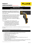
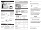
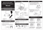
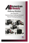
Broady Flow Control Limited,
English Street,
Kingston upon Hull,
East Yorkshire,
HU3 2DU.
www.broady.co.uk
Telephone: 01482 619600
Facsimile: 01482 619700
SERVICE MANUAL
Series 2500/F
Safety Relief Valve
(Screwed)
SD23/250F-GA1 10/01
Series 2500/F Safety Relief Valve
1. OPERATION
Safety Relief valves are automatic discharge valves and have the function of maintaining the pressure
in a circuit below a set limit.
A Safety Relief valve consists of three main parts:
Nozzle Disc Spring -
Which permits the discharge medium to be piped away correctly.
Which closes the Nozzle discharge orifice.
Which opposes the force of the medium below the Disc.
When the force exerted by the pressure of the medium on the disc exceeds the spring force, the disc
begins to lift. The pressure exerted by the discharge medium on the surface of the ring shaped
chamber of the disc holder produces immediate opening of the valve. The distance of the blowdown
ring relative to the disc holder has an effect on the change in the pressure between opening and
closing for valves used with gases and vapours.
For valves used with liquids, the blowdown ring must be lowered in such a way as to make it
ineffectual.
2. INSTALLATION
During mounting the Valve:
- Avoid bumping or shaking the Valve to prevent damaging the flange faces and misalignment of the
trim.
- Blow through the circuit line on which the Valve is to be installed to remove any foreign matter
(welding chips etc.)
- Clean thoroughly the Valve and Nozzle connections: impurities on the Nozzle may damage the
Valve Seat during popping.
- Install the Valve in the vertical position only with the inlet downwards.
- Tighten uniformly the bolts of the flanges connecting the Valve to the pipework.
- Use inlet and outlet pipework as short as possible and of dimensions equal to the valve
connections.
- Avoid strain on the outlet flange, with suitable supports.
- Secure the outlet pipework in order to reduce vibration and to avoid strain on the outlet flange.
- Avoid elbows with small curvature radius on the outlet pipe: for high temperature gas and vapour
discharge, use expansion joints.
After the Valve has been installed make it pop at least twice to allow automatic alignment of the trim.
Misalignment may be caused accidentally during transport or during installation of the Valve.
2
Series 2500/F Safety Relief Valve
3. TESTS
The valves are factory tested before consignment, according to the Customer’s required
specifications detailed in their order. It is nevertheless recommended that the following tests be
carried out before installation of the valve.
3.1 Disc seal
For this operation it is necessary to.
-
Connect the valve inlet to a container (fig 1) in which the pressure may be raised
gradually and measured by the means of a pressure gauge.
Close the valve with a plate, in the centre of which a tube is inserted which is immersed in a
container of water.
The seal test consists of raising the inlet up to 90% of the set pressure and checking that the number
of air bubbles per minute which pass through the container do not exceed the values shown in the
Valve Testing Data table (page 5).
Should the leakage exceed the values given in the testing data table, then consult the table “FAULTS
IN OPERATION” on page 7
3.2 Set pressure
For this operation it is necessary to connect the valve inlet to a container in which the pressure may
be raised gradually and measured by means of a pressure gauge.
The test consists of checking that the valve starts opening at the required set pressure (refer to Valve
Testing Data table)
Changes outside the stated tolerances must be corrected by varying the spring compression, by
means of the spring adjusting screw.
To regulate the set pressure (see fig 1).
(1)
(2)
(3)
(4)
(5)
(6)
Place the valve on the tests stand (fig 1) with no pressure on the valve inlet.
Remove the cap (3)
Prevent the disc-holder rotating by means of holding the spindle (5) with a screwdriver inserted
into the slot at the end.
Loosen lock nut (14) of the adjusting screw (13)
Regulate the spring adjusting screw until the desired set pressure is reached.
Do not allow the disc holder to rotate.
Reassemble the cap (3)
NOTE: For each successive set pressure check; the lock nut must be tightened.
3
Series 2500/F Safety Relief Valve
4
Series 2500/F Safety Relief Valve
Tag Number
Valve Set at
Cold Set
Seat Tightness
VALVE TESTING DATA
Refer to Name Plate on Valve
Refer to Name Plate on Valve
Refer to Name Plate on Valve
40 Bubbles / min at 90% of the set pressure
4. OVERHAUL
Overhaul of the Valve means dismantling it completely to clean every part thoroughly and to decide
whether the various parts may be re-used, adjusted or substituted.
It is necessary to check that the contact surfaces of the seat and disc area are in perfect condition.
Should scratching or pitting be present the surfaces must be ground and then lapped.
4.1 Lapping the Disc
Use a cast iron block with a perfectly smooth and flat surface, or a plate glass block of a suitable size. For
a perfect lap pass the disc across the smooth surface of the block, after applying a small quantity of
lapping compound, using a figure of eight movement. Lift the disc periodically away from the block so
that the compound may flow from the edges towards the centre.
4.2 Lapping the Nozzle Seat
Use a cast iron or plate glass block as for lapping the disc, and check that this does not tilt to avoid
rounding off the edges. After spreading the lapping compound over the smooth surface of the block, pass
the Nozzle seating surface over the block using a figure of eight movement. During the lapping operation,
make sure that there is no foreign matter on the lapped surface or on the block. The lapped parts must be
carefully cleaned before assembling, so as to remove every trace of lapping compound.
5. NORMAL MAINTENANCE
The most frequent operation to be carried out is a precise check, made at regular intervals, to observe
whether any obvious faults exist in the different parts of the Valve. It should be checked first of all that
there are no leakage’s; these must always avoided, especially when the medium is poisonous, highly
volatile or very explosive. Carry out periodic venting for Valves fitted with lifting devices to check regular
operation (at least two or three times a year). During these tests the pressure must be at least 75% of the
full working pressure.
5
Series 2500/F Safety Relief Valve
6. DISASSEMBLY
(1)
(2)
(3)
(4)
(5)
(6)
(7)
(8)
(9)
Remove Cap & Joint (3 & 32).
Measure position of the Adjusting screw (13) and record for re-assembly purposes.
Slacken Locknut (14) and unscrew Adjusting screw (13).
Remove Clampscrew (16).
Unscrew Nozzle (2), and lift off Body (1) and Joint (31).
Lift off the Spindle/Valve Lid assembly (parts 4, 5, 7, 9, 11 & 35).
Lift off the Spring Carriers (17) and Spring (29).
Remove Disc (4) from the Disc Holder (7) by tapping Disc Holder firmly onto
a clean wooden surface, care should be taken not to misplace the Circlip (35)
and Ball (11).
Unscrew Blowdown Ring (8) from Nozzle (2).
7. ASSEMBLY
Reassemble the Valve carrying out the operations listed for disassembly in reverse and taking care to:
Avoid scratching on the lapped surfaces of the Seat and Disc.
Clean the trim thoroughly throughout.
Spread with graphite grease all threads, the Adjusting Screw and the Spring Carrier.
FOR VALVES FOR OXYGEN SERVICE, CAREFULLY DE-GREASE ALL PARTS BEFORE ASSEMBLY.
Fit new gaskets. To prevent damage to Disc/Nozzle faces hold spindle with screwdriver in the slot on the
end of Spindle turning whilst compressing Spring.
6
Series 2500/F Safety Relief Valve
8. FAULTS IN OPERATION
FAULT
CAUSES
Leakage
Discharge at incorrect
pressure
Chatter (rapid opening
and closing cycle).
SOLUTIONS
(1) Presence of foreign matter between
seat and disc
(1) Discharge valve once or twice
consecutively. Should leakage continue,
disassemble valve and clean trim.
(2) Scratching or pitting on seat surface
(2) Disassemble valve, grind and lap seat.
(3) Valve used with a medium other than
specified when ordering
(3) Lap seat and disc more finely if the valve
originally ordered for liquid service, is
used with gas
(4) Valve not mounted vertically.
(4) Correct installation.
(1) Variable back pressure
(1) Check that discharge takes place in piping
whose dimensions are equal to or greater
than those of the outlet connections of the
valve, and that the discharge piping is free
from obstruction.
(2) Back pressures different from
specified when ordered
(2) The valve must be re-calibrated
correcting the spring compression for the
revised set pressure.
(3) Loosening of lock nut on spring
adjusting screw.
(3) Tighten lock nut after re-calibrating the
valve.
(4) Poor trim alignment.
(4) Discharge the valve 2 or 3 times to allow
self-alignment of the trim.
(1) Blowdown ring incorrectly adjusted.
(1) Ensure that the blowdown ring is in the lowest
position for liquid service. For valves used on
gas; regulate suitably.
(2) Insufficient discharge capacity.
(2) Check that the discharge piping is not too long.
Check that the valve is not undersized.
9. PARTS LIST
ITEM
1
2
3
4
5
7
8
9
11
13
14
15
16
17
18
29
31
32
33
34
35
36
DESCRIPTION
BODY
NOZZLE
CAP
DISC
SPINDLE
DISC HOLDER
BLOWDOWN RING
PIN
BALL
ADJUSTING SCREW
LOCKNUT (ADJUSTING SCREW)
SCREWED PIN
CLAMPSCREW
SPRING CARRIER
LOCKNUT (SCREWED PIN)
SPRING
JOINT (NOZZLE)
JOINT (CAP)
JOINT (CLAMPSCREW)
JOINT (PLUG)
CIRCLIP
PLUG
7
QTY
1
1
1
1
1
1
1
1
1
1
1
1
1
2
1
1
1
1
1
1
1
1
Series 2500/F Safety Relief Valve
Fig 2
Note - Valve illustrated shows Female Type Inlet (Part 2) this is also available with Male connections
8