1
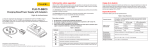
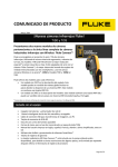
OPERATING INSTRUCTIONS
Category
Important! When fitting Pressure Gauge to valve body,
ensure threads do not penetrate, interfering with internal
moving parts, otherwise valve could jam.
II Pressure Accessory
Type C3 Reducing Valve
Notified Body No. 0038
Application
Suitable for compressed air, gas, water and oil service.
Operation
The outlet pressure can be varied as required by compressing or relaxing
the spring using the adjusting screw:
Maintenance
Examine annually for signs of defect, damage or deterioration.
Give special attention to contact/seating faces, if damaged these should
be re-faced. Discs, diaphragms, seals and springs should be replaced if
there is any sign of deterioration.
All parts should move freely in their respective guides.
Note: Quote the unique valve serial number when ordering spare parts.
Clockwise turns compress the spring increasing outlet pressure.
Important: All manual handling operations should be carried out in
compliance with the Manual Handling Operations Regulations 1992
(SI 1992/2793) (EC Directive 90/269/EEC).
Storage
If valve is bound to be stored longer than 6 months, turn back adjusting
screw to remove compression from spring. (Re-adjust spring
compression on installation).
Valves with Screwed ends shall have plugs fitted in their connections to
prevent ingress of dirt etc. Flanged valves shall have their bores blanked
off.
We recommend that plugs/blanks be removed immediately prior to
installation.
Installation and Commissioning
It is most important that the pipeline be clean and free from dirt, scale,
etc.
Fit valve in pipeline with flow as indicated by arrow cast on valve body
and with adjusting screw directly above or below pipeline.
It is also advisable to fit a stop valve on high-pressure side of line.
Before dismantling ensure that the valve has been isolated
from the pressure and the adjusting screw has been
removed.
Item Description
1
Dismantling and Reassembly
To replace Diaphragm: When the pressure is off: Remove; Adjusting
Screw (18); Bonnet (15); Spring Carrier (16) and Spring (14); Piston Nuts
(11 & 12) and Piston (10). Diaphragm (9) should come away freely.
Clean the diaphragm seating spigot on Body (3). Follow reassembly
instructions below.
Qty
Cap
1
Joint (Cap)
1
3
Body
1
4
Saddle Cap
1
5
Disc Holder
1
Disc
1
Saddle
1
2
6
7
To replace Disc: Follow the instructions for replacement of Diaphragm;
this will leave Saddle (7) unrestricted at Diaphragm end of valve. Remove
Cap (1) by turning in an anticlockwise direction and remove Joint (2),
this will give access to Saddle Cap (4) and Loading Spring (21 - If fitted ).
Remove Loading Spring then hold unrestricted Saddle (7) at Diaphragm
end of valve, unscrew Saddle Cap in an anticlockwise direction. Remove
Disc Holder (5); The Disc can then be prised out using a small
screwdriver (care must be taken not to damage Disc Holder).
The new Disc can be pushed into the Disc Holder; we recommend using
LOCTITE® 415 to bond it in place. Follow reassembly instructions below.
12
8
Pin
1
Diaphragm
1
10
Piston
1
11
Nut
1
Locknut
1
13
Piston Bolt
1
14
Spring
1
15
Bonnet
1
Note: Replace all joints with new ones.
16
Spring Carrier
1
Reassembly: The valve is reassembled in reverse order of above
dismantling procedures, in addition Disc must be held in fully closed
position while new Diaphragm is fitted, ensuring that faces of collar on
Saddle and diaphragm spigot on Body are level (as shown in the
illustration). Before fitting Bonnet (15) make sure Saddle (7) is square in
Body (3) and does not touch side of nozzle. Readjust the pressure as
necessary by means of the Adjusting Screw (18); Locknut (17) should
then be tightened.
17
Locknut, Adjusting Screw
1
18
Adjusting Screw
1
19
Setscrews
8
20
Plug
1
21
Loading Spring*
1
LOCTITE® is a Registered Trade Mark of Loctite Corp. USA
9
* If Required
Recommended spare parts
© Broady Flow Control Limited 2002
Lifting and Handling
Wooden cases should be lifted using either a Fork Lift
Vehicle or a Crane with adequate Safety Approved slings
applied to carry the weight, which will be evenly distributed
within the case.
Safety Warning!
SD23/C3 PRV Version 1.0 04/02 - APD
Anti-clockwise turns relax the spring decreasing outlet pressure.
SD23/C3 PRV Version 1.0 04/02 - APD
© Broady Flow Control Limited 2002