1
OPERATING INSTRUCTIONS
Safety Accessory
To regulate the set pressure:
Type 3500 Relief Valve
Notified Body No. 0038
1. Fit valve to Test Rig with no pressure on valve inlet.
Installation and Commissioning
2. Remove the cap (3).
It is most important that the pipeline and valve
connections be clean and free from dirt, scale, etc.
3. Prevent Disc Holder (7) rotating by holding Spindle (5) with screwdriver in
slot on Spindle end.
Avoid bumping or shaking valve, to prevent misalignment of trim
and damage to flange faces.
Application
4. Loosen Locknut (14) (fitted to Adjusting Screw (13))
Suitable for compressed air, gas, water, oil and steam service.
5. Adjust using Adjusting Screw (13) until the desired set pressure is achieved.
Do not allow Disc Holder (7) to rotate.
Operation
The set pressure can be varied as required by compressing or
relaxing the spring using the adjusting screw:
Clockwise turns compress the spring increasing the set pressure.
Anti-clockwise turns relax the spring decreasing the set pressure.
Lifting and Handling
Wooden cases should be lifted using either a Fork Lift Vehicle
or a Crane with adequate Safety Approved slings applied to
carry the weight, which will be evenly distributed within the
case.
Important: All manual handling operations should be carried out in
compliance with the Manual Handling Operations Regulations 1992
(SI 1992/2793) (EC Directive 90/269/EEC).
Storage
Valves with Screwed ends shall have plugs fitted in their
connections to prevent ingress of dirt etc. Flanged valves shall have their
bores blanked off.
We recommend that plugs/blanks be removed immediately prior to
installation.
Safety Warning!
Discharge from outlet may be violent and must not be
allowed to create a hazard to persons or property.
6. Reassemble Cap (3).
Fit valve in pipeline with flow direction as indicated by arrow cast
on valve body; with inlet down and Adjusting Screw in vertical
position above pipeline.
Note: For each set pressure check; Locknut (14) must be tightened.
It is also advisable to fit a stop valve on high-pressure side of line.
Opening Pressure Adjustment Settings
The following table gives an approximate guide to the amount of adjustment needed
to vary the opening pressure. Variations in springs are not taken into account.
Orifice
D
Percentage
variation of opening
pressure relative to
1mm of adjusting
screw stroke
E
F
G
H
J
33 22 18 15 12
9
K
L
M
7.5 5.5 4.5
N
4
P
Q
R
3.5 2.5 2.2 1.8
Cold Setting of high temperature valves
Percentage increase over set pressure
from -265 to +100
-
from 101 to 230
2%
from 231 to 480
3%
from 481 to 540
4%
It is recommended that the following tests be carried out before
installation of the valve: Seat tightness and set pressure.
Test Equipment
Connect valve inlet to a pressure vessel, of at least 100 litres capacity, in
which pressure may be raised gradually and measured by means of a
precision pressure gauge.
Raise inlet pressure to 90% of set pressure and check that the number of
air bubbles per minute which pass through the water does not exceed the
values below:
Orifice
Maximum Leakage
(Bubbles per minute)
From D to F
40
From G to T
20
Should the leakage exceed the stated value, refer to table "Faults in
Operation" (Fig. 2)
EQUIPMENT FOR SEAT TIGHTNESS TEST
Set pressure Kg/cm²
Percentage increase over set pressure
from 0.5 to 7
2%
from 7.1 to 21
3%
from 21.1 to 70
4%
from 70.1 to 210
5%
When there is a constant back pressure, valves without a balancing seal are set
differentially.
Example: A valve, without a balancing seal, has a set pressure of 20 kg/cm²
and a constant back pressure of 3 kg/cm²: Set valve at 20 - 3 = 17kg/cm². This
value is then increased by the corresponding percentage required for the
relative high temperature.
Valves fitted with a balancing seal are only subject to variation due to high
temperature or steam service.
Consult Broady Technical Staff before making any changes
to process conditions.
Blowdown
Broady Safety Relief Valves are fitted with a single blowdown ring which may
be used to regulate the blowdown.
Note: Blowdown tests must be carried out with the use of a compressed air
plant of high capacity especially for large sized valves.
When the desired blowdown is reached, tighten the Clampscrew (4).
The blowdown test, carried out with low discharge capacities, gives a reseating
pressure higher than that, which would occur in discharge conditions.
Therefore, to obtain the same reseating conditions as for a valve during
operation, lower the blowdown ring by two notches.
Changes outside the stated tolerances must be corrected by varying the
spring compression using the Adjusting Screw (13).
Leakages must be repaired immediately, especially when the
medium is poisonous, highly volatile or very explosive.
When valve is fitted with lifting device, vent periodically (at least
three or four times a year) to check operation. During these tests
the pressure must be at least 75% of the full working pressure.
Annual Checks:
Springs should be replaced if there is any sign of deterioration.
All parts should move freely in their respective guides.
Note: Quote the unique valve serial number when ordering spare
parts.
Lapping the Disc
Use a cast iron or plate glass block of suitable size, with a
perfectly smooth and flat surface. Apply a small quantity of
lapping compound to smooth surface of block. Pass Disc (4),
across smooth surface, in a figure of eight movement. Lift Disc
periodically away from block so that lapping compound may flow
from edges towards centre.
Lapping the Nozzle Seat
Use a cast iron or plate glass block of suitable size; check that it
does not tilt, to avoid rounding off edges. Apply lapping
compound to smooth surface of block. Pass Nozzle (2) seating
surface across smooth surface in a figure of eight movement.
During lapping operation, make sure no foreign matter is on either
lapped surface or block.
Note: Lapped parts must be carefully cleaned before assembling,
to remove every trace of lapping compound.
Safety Warning!
Safety Warning!
ii) Rotate blowdown ring (33) upwards to increase/downwards to decrease
blowdown.
Do not pop the valve if a tank of adequate capacity is not available,
to avoid denting the seat, which would cause leakage.
Regular Checks:
Check at regular intervals, for signs of obvious faults.
Give special attention to contact/seating faces, if damaged these
must be re-machined and lapped in.
i) Loosen Clampscrew (4) to allow rotation of Blowdown ring; if the ring is not
accessible through the valve outlet, remove Clampscrew completely and rotate
the ring with a screwdriver inserted into the hole left by the screw.
Set Pressure Test
Check that valve starts opening at required set pressure (refer to Valve
Nameplate for correct value), tolerating a change of +/- 0.15kg/cm2 for
set pressures of less than 5kg/cm2 and of +/- 3% for set pressures of
5kg/cm2 and higher.
After valve has been installed make it pop at least twice to allow
automatic alignment of trim.
Cold Setting of valves for steam service
To correct the blowdown setting proceed as follows:
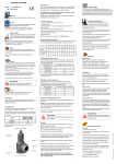
Fig. 1 - API 527 compliant leakage detector
Avoid elbows with small curvature radii on the outlet pipe: for high
temperature gas and vapour discharge, use expansion joints.
Examine annually for signs of defect, damage or deterioration.
Setting valves with constant back pressure
Seat Tightness Test
The valve outlet should be fitted with an appropriately sized leakage
detector (see Fig. 1) in accordance with API 527.
Secure outlet pipework in order to reduce vibration and avoid
strain on outlet flange.
This percentage increase offsets relaxation of the spring, caused by expansion
of the body and bonnet.
When possible, valves for steam service should be tested with steam.
When these valves are set with air at ambient temperatures, the following
percentage increases in set pressure must be borne in mind:
Testing
Uniformly tighten fasteners securing valve connections to pipework.
Maintenance
Cold setting of high temperature valves is often necessary. In this case valves
must be set at a pressure above the set pressure according to the percentages
shown in the following table:
Working temperature °C
T
Use inlet and outlet pipework as short as possible and of
dimensions equal to the valve connections.
In no case must the blowdown ring be fitted in contact with the disc
holder. The blowdown ring must be rotated at least two notches to lower
it away from the disc holder.
Before dismantling ensure that the valve has been
isolated from the pressure and the adjusting screw
has been removed.
Dismantling and Reassembly
Dismantling:
1. Remove Cap & Joint (3 & 32).
2. Measure position of the Adjusting screw (13) and record for reassembly purposes.
3. Unscrew Locknut (14) and remove with Adjusting screw (13).
4. Remove Bonnet (10) from Body (1) by unscrewing Nuts (24).
5. Remove Spring Carriers (17) and Spring (29) from Spindle (5).
6. Using Spindle (5) as a handle, lift out remaining internals.
7. Remove Pin (9) and unscrew Stem (11) from Disc Holder (6).
8. Remove Stem (11) from Guide (25).
9. Remove Disc (4) from Disc Holder (6) by tapping Disc Holder
firmly onto a clean wooden surface, care should be taken not to
misplace the Circlip (35).
10. Unscrew Clampscrew (16) from Body (1).
11. Unscrew Blowdown Ring (8) from Nozzle (2).
12. Unscrew Nozzle (2) from Body (1).
© Broady Flow Control Limited 2002-2003
IV
Note: Replace all Joints with new ones.
Installation Handling
When moving the valve, for installation/maintenance purposes, it is
recommended that an appropriate M10/M20 Lifting Eyebolt (65)† , fitted in
place of Plug/Gag (36), be used. Utilising this Eyebolt a Safety Approved
chain/strap, of adequate strength, may then be used, in conjunction with a
suitable crane, to lift and move the valve . † Lifting Eyebolt (65) Not supplied.
Danger of Explosion!
Oxygen Service - Carefully degrease all components
before assembling valves. Failure to do so will result
in an explosion.
SD23/3500 Version 2.1 07/03 - APD
Category
OPERATING INSTRUCTIONS
Danger of Explosion!
Fig. 2 - Faults in Operation
Oxygen Service - Carefully degrease all components
before assembling valves. Failure to do so will result in
an explosion.
FAULT
Leakage
Reassembly:
CAUSES
(1) Presence of foreign matter between
seat and disc
Carry out reverse of operations listed for disassembly, taking care to:
SOLUTIONS
(1) Discharge valve once or twice
consecutively. Should leakage continue,
disassemble valve and clean trim.
Avoid scratching lapped surfaces. Note: To prevent damage to
Disc/Nozzle faces hold Spindle (5) with screwdriver in slot on Spindle end;
turn whilst compressing Spring.
Clean the trim thoroughly throughout. Lubricate Adjusting Screw, Spring
Carrier and all threads with graphite grease.
(2) Scratching or pitting on seat surface
(2) Disassemble valve, grind and lap seat.
(3) Valve used with a medium other than
(3) Lap seat and disc more finely if the valve
specified when ordering
originally ordered for liquid service, is
used with gas
Discharge at
incorrect
pressure
(4) Valve not mounted vertically.
(4) Correct the installation.
(1) Variable back pressure
(1) Check that discharge takes place in piping
whose dimensions are equal to or greater
than those of the outlet connections of the
valve, and that the discharge piping is free
from obstruction.
(2) Back pressures different from
specified when ordered
(2) The valve must be re-calibrated
correcting the spring compression for the
revised set pressure.
(3) Loosening of lock nut on spring
adjusting screw.
(4) Poor trim alignment.
(3) Tighten lock nut after re-calibrating the
valve.
(4) Discharge the valve 2 or 3 times to allow
self-alignment of the trim.
Chatter (rapid
opening and
closing cycle)
(1) Blowdown ring incorrectly adjusted.
(1) Ensure that the blowdown ring is in the lowest
position for liquid service. For valves used on
gas; regulate suitably.
(2) Insufficient discharge capacity.
(2) Check that the discharge piping is not too long.
Check that the valve is not undersized.
Qty
Body
1
2
Nozzle
1
3
Cap
1
4
Disc
1
5
Spindle
1
6
Disc Holder
1
8
Blowdown Ring
1
9
Pin (Disc Holder)
1
10
Bonnet
1
11
Stem
1
12
Collar
1
13
Adjusting Screw
1
14
Locknut (Adjusting Screw)
1
15
Screwed Pin
1
16
Clampscrew
1
17
Spring Carrier
2
18
Locknut (Screwed Pin)
1
19
Pin (Collar - Large)
1
20
Pin (Collar - Small)
1
21
Bellows
1
22
Washer (when Bellows not fitted)
1
23
Stud (Body/Bonnet)
Various
24
Nut (Body/Bonnet)
Various
25
Guide Assembly
1
28
29
Drain Plug
Spring
1
1
30
Joint (Bellows)
1
31 Joint (Guide)
1/2*
32 Joint (Cap)
1
33 Joint (Clampscrew)
1
34 Joint (Plug/Gag)
1
35
Circlip (Disc)
1
36
Plug/Gag
1
65
Lifting Eyebolt
1
* Valves not fitted with Bellows have two Guide Joints.
Recommended spare parts
†
Lifting Eyebolt (65) Not supplied.
© Broady Flow Control Limited 2002-2003
1
SD23/3500 Version 2.1 07/03 - APD
Item Description