1
MP1100/MP1101
Plasma Freezers
Low Temperature Freezing
System for Blood Components
Operator & Service
Manual
37-00-053B
© ThermoGenesis Corp. 2001, 2005
Revision History
Rev A
Rev B
August 2005
January 2013
Table of Contents
Chapter 1 – INTRODUCTION
Intended Use .............................................. 1-1
How to Use this Manual ................................ 1-1
Text Conventions ......................................... 1-2
Electrical Safety........................................... 1-2
Safety Precautions ....................................... 1-3
Copyright Notice .......................................... 1-4
Trademarks ................................................ 1-4
Disclaimer................................................... 1-5
Contact Information ..................................... 1-5
Limited Warranty ......................................... 1-6
Warranty .................................................... 1-6
Procedure ................................................... 1-7
Limitations.................................................. 1-7
Chapter 2 – OVERVIEW
Specifications .............................................. 2-1
Overview .................................................... 2-2
Safety Devices ............................................ 2-3
Major Components of the Freezer................... 2-3
InstaCoolant IV ........................................... 2-9
Installation, Service and Maintenance Forms.... 2-9
Chapter 3 – INSTALLATION
Unpacking and Inspection ............................. 3-1
Connecting the Desiccant Filter Assembly —
P/N’s 8-1100-20/21/23 and
8-1101-20/21/23 only......................................3-1
MP1100 Plasma Freezer – Operator and Maintenance Manual, 37-00-053.B
TOC-1
Connecting Desiccant Filter Assembly and
Vacuum Pump — P/N’s 8-1100-27 and
8-1101-27 only ...................................... 3-2
Placing the Freezer in Position ....................... 3-3
Electrical Installation and Specifications .......... 3-5
Installing the Control Arm and Control
Panel Housing ........................................ 3-5
Connecting all the Wires ............................... 3-7
Adding the InstaCoolant IV to the Freezer ....... 3-8
Removing and Replacing a Pocket —
P/N’s 8-1100-20/21/23 and
8-1101-20/21/23.................................... 3-8
Removing and Replacing a Pocket —
P/N’s 8-1100-27 and 8-1101-27 ............... 3-9
Adjusting the Safety Thermostat .................. 3-10
Starting the MP1100 Freezer ....................... 3-10
Temperature Pull-down............................... 3-11
Verifying Operating Temperature ................. 3-13
Chapter 4 – OPERATING INSTRUCTIONS
Introduction ................................................ 4-1
Factors Influencing Plasma Freeze Times......... 4-2
Operational Input Codes ............................... 4-2
Setting the Operating Temperature ................ 4-3
Verifying Operating Temperature Calibration.... 4-4
Recalibrating the Operating Temperature ........ 4-4
Setting the Freeze Cycle Time........................ 4-5
Running the Freeze Cycle.............................. 4-6
Running the Night Cycle................................ 4-7
TOC-2
MP1100 Plasma Freezer – Operator and Service Manual, 37-00-053.B
Chapter 5 – MAINTENANCE
Maintenance Schedule ................................ 5-1
Checking and Cleaning the Pockets............... 5-1
Cleaning the Deck ...................................... 5-2
Removing and Replacing a Pocket —
P/N’s 8-1100-20/21/23 and
8-1101-20/21/23.................................. 5-2
Removing and Replacing a Pocket —
P/N’s 8-1100-27 and 8-1101-27 ............. 5-3
Repairing a Pocket ..................................... 5-4
Cleaning the Freezer .................................. 5-5
Checking the Desiccant Filters ..................... 5-5
Checking the Pump Motor Cooling Fans ......... 5-5
Checking the Coolant Level ......................... 5-6
Checking the Lid Gasket Seals ..................... 5-6
Checking the Hinges................................... 5-6
Checking the Deck Screws .......................... 5-7
Verifying Operating Temperature Calibration.. 5-7
The Defrost Cycle ...................................... 5-7
Before Starting the Defrost Cycle ................. 5-7
Initiating the Defrost Cycle.......................... 5-8
Draining Water from the System .................. 5-9
Restoring Freezer to Operating Temperature...5-10
Maintaining the Refrigeration System...........5-10
Chapter 6 – TROUBLESHOOTING
Introduction .............................................. 6-1
No Power to Unit........................................ 6-2
Freezer Display is Lit, but Pumps Do Not Work..... 6-2
Coolant Chamber Fills Initially, but During
the Cycle the Coolant Level Drops Off ...... 6-2
Product is not Completely Frozen ................. 6-2
Coolant Temperature is too High .................. 6-3
MP1100 Plasma Freezer – Operator and Service Manual, 37-00-053.B
TOC-3
Condensing Unit (Refrigerant System)
Shuts Down ......................................... 6-3
Pockets Tearing or Ripping .......................... 6-3
Vacuum Light is Not Activating .................... 6-3
Chapter 7 – REPLACING PARTS FOR THE MP1100 FREEZER
Safety Precautions ..................................... 7-1
Hinge ....................................................... 7-2
Lid ........................................................... 7-4
Lid Gasket ................................................ 7-4
Lid Gasket Plate......................................... 7-5
Deck ........................................................ 7-8
Motorbox Cover ......................................... 7-8
Control Panel ...........................................7-11
Power Panel .............................................7-12
Probe Box ................................................7-12
Motorbox – Removal and Installation ...........7-14
Motorbox – Disassembly and Assembly ........7-16
Defrost Heater..........................................7-18
Safety Thermostat ....................................7-19
Sensor Temperature Probe .........................7-22
Chamber .................................................7-23
Condensing Unit .......................................7-23
Chapter 8 – PARTS LIST
Parts List .................................................. 8-1
Ordering Information.................................. 8-2
Chapter 9 – REFERENCE DRAWINGS
7-24-033 Condensing System...................... 9-1
7-35-118 Electrical Box .............................. 9-2
7-65-018 Temp Probe ................................ 9-6
7-65-046 Motorbox Assembly ...................... 9-7
TOC-4
MP1100 Plasma Freezer – Operator and Service Manual, 37-00-053.B
Appendix A – FORMS
Installation Checklist .................................. A-1
Daily Maintenance Checklist ........................ A-2
Weekly Maintenance Checklist ..................... A-3
Monthly Maintenance Checklist .................... A-4
Quarterly Maintenance Checklist .................. A-5
Bi-Annual Maintenance Checklist .................. A-6
Parts Order Form ....................................... A-7
Service Form............................................. A-8
MP1100 Plasma Freezer – Operator and Service Manual, 37-00-053.B
TOC-5
Chapter
1
Introduction
TABLE OF CONTENTS
Intended Use ........................................1-1
How to Use this Manual ..........................1-1
Text Conventions...................................1-2
Electrical Safety.....................................1-2
Safety Precautions .................................1-3
Copyright Notice....................................1-4
Trademarks ..........................................1-4
Disclaimer ............................................1-5
Contact Information ...............................1-5
Limited Warranty ...................................1-6
Warranty ..............................................1-6
Procedure .............................................1-7
Limitations............................................1-7
Intended Use
NOTE: There are two types of MicroCascade freezers, the
MP1100 and MP1101. The only difference between the two models
is the certification. The MP1101 is the model CE-certified for sale
in Europe. Since operation and service requirements are the same
for both freezers, they will be referred to collectively as
“MP1100 Freezer” throughout the manual.
The ThermoGenesis Corp. MP1100 freezer with MicroCascade
Refrigeration is intended for the fast, efficient freezing of blood
and blood components.
This Operator and Service manual is organized to provide easy
access to setup and maintain the MP1100 Freezer. Please read this
manual in its entirety.
How to Use This Manual
Key Indicators
The “Pen-in-Hand” icon in the sidebar indicates to pay close
attention to the indicated text.
The “Exclamation” icon in the sidebar indicates a Caution or
Warning about a potential hazard. For example: injury to the
operator or other personnel and potential damage to the
equipment.
The “Lightning Bolt” icon in the sidebar indicates a Caution or
Warning about a potential electrical hazard. For example: injury to
the operator or other personnel and potential damage to the
equipment.
The “Flame” icon in the sidebar indicates a Caution or Warning
about a potential fire or explosion hazard. For example: injury to
the operator or other personnel and potential damage to the
equipment.
The “Freeze” icon in the sidebar indicates a Caution or Warning
about a potential hazard to cold or frostbite. For example: injury
to the operator or other personnel and potential damage to the
equipment.
MP1100 Freezer – Operator and Maintenance Manual, 37-00-053.B
1-1
Text Conventions
To convey information readily and consistently, certain text
conventions are used throughout this manual. These conventions
are as follows:
TEXT CONVENTION
Numbered Lists
USED FOR
Numbered lists should be carried out in the
order listed (for example);
1. Remove the screws from the rear of the
motor box.
2. Remove the screws from the Control
Panel.
Bulleted Lists
Bulleted Lists indicate items to be carried out,
but not necessarily in sequence (for
example):
Check the fuses.
Make sure all snap connectors are tight.
Bold Typeface,
Uppercase
Calls attention to a CAUTION, WARNING,
or DANGER.
Bold Typeface,
lowercase
Emphasizes any term or component that is
being described or referred to.
Italics
Used in designating another section in this
Operator and Maintenance Manual that
should be consulted (for example):
See Troubleshooting – Chapter 6
Electrical Safety
CAUTION: The MP1100 Freezer is designed in accordance with
Protection Class I (IEC). The chassis of the system is connected to
ground by means of a cable, and surfaces on the system that the
operator may come in contact with are connected to the chassis
by means of screw connections. For protection against electrical
hazards, the system must be directly connected to a properly
grounded electrical source approved by a qualified electrician.
Contact Helmer Technical Service for assistance if you have any
questions concerning the electrical connection for the MP1100
Freezer. When servicing the MP1100 Freezer, make sure the
power switch is turned off. If unit is hardwired, turn off circuit
breaker to unit.
1-2
MP1100 Freezer – Operator and Service Manual, 37-00-053.B
Safety Precautions
Safety precautions that are necessary when operating,
maintaining, and troubleshooting the MP1100 Freezer are outlined
below. It is important that these precautions be carefully read and
understood. This information should also be made available to new
employees.
CAUTION: For greatest assurance of proper and safe operation,
keep this manual in a place where it is readily accessible for
reference.
NOTE: During disassembly, keep parts in order to facilitate reassembly.
CAUTION: Prior to starting any electrical work, disconnect all
power to the freezer.
NOTE: Check all hose and wiring connectors to make sure they are
secure and correct.
NOTE: Special tools and materials may be required for certain
repairs and maintenance. Be sure to use these tools and materials
and follow the proper work procedure.
NOTE: When replacing fuses, be sure the new fuse has correct
amperage rating.
NOTE: General ESD Control Practices should be utilized when
servicing or repairing this equipment.
CAUTION – FIRE DANGER: Danger of fire if the vapors from the
InstaCoolant IV are allowed to reach 42°C (108°F). For
operational purposes THERMOGENESIS CORP. has set the limit on the
MP1100 Freezer safety thermostat at 27°C (80°F).
CAUTION – FIRE DANGER: When warming the coolant during a
defrost operation, DO NOT PLACE AN ELECTRIC IMMERSION
HEATER IN THE COOLANT.
MP1100 Freezer – Operator and Maintenance Manual, 37-00-053.B
1-3
CAUTION: Make sure the InstaCoolant IV is above freezing (0C
(32F)) before performing any service inside the machine. Placing
your hands in the coolant when it is below freezing creates an
extreme frostbite danger.
CAUTION: The 508b SUVA 95 is a high-pressure refrigerant.
Standard refrigeration components (gauges and hoses) cannot be
used with this refrigerant because of the high pressure. When
servicing the condensing unit, use protective gloves and protective
eyewear to prevent frostbite from exposure to refrigerant.
NOTE: This refrigerant would only need to be checked if all other
systems are working, but the freezer is not holding temperature.
CAUTION: The condensing unit should only be serviced by a
technician trained in cascade (high-pressure) refrigeration
systems.
CAUTION: The user shall be made aware that, if the equipment is
used in a manner not specified by the manufacturer, the
protection provided by the equipment may be impaired.
Copyright Notice
© 2005, 2010 ThermoGenesis Corp. All Rights Reserved
The material in this manual is intended for use by the purchaser of
the equipment covered by the manual. Permission is granted to
the purchaser to make one copy of the manual for record
retention and internal personal use. This does not create a license
to the purchaser under any copyright, trademark, patent, or other
intellectual property right. For additional copies of this manual,
contact Helmer Technical Service, or the equipment supplier.
Trademarks
ThermoGenesis Corp. proprietary trademarks identify products
and services of ThermoGenesis Corp., are the property of
ThermoGenesis Corp. and are protected under State and Federal
trademark laws, and under international treaties. Those
1-4
MP1100 Freezer – Operator and Service Manual, 37-00-053.B
proprietary trademarks and service marks may not be used,
except as provided by law, without the prior written consent of
ThermoGenesis Corp. Trademarks and service marks include
ThermoGenesis® and MicroCascade. Companies own other brand
trademarks and tradenames mentioned in this manual.
Disclaimer
ThermoGenesis Corp. has thoroughly reviewed the contents of this
manual to make it an informative and easy-to-use guide for the
operation of the equipment and devices described herein. All
statements, technical information and recommendations contained
in this manual or related documentation are current and believed
to be reliable as this document goes to press. For this reason, the
contents of this manual are not intended to be and should not be
understood as representations or warranties concerning the
equipment and devices described herein.
The ThermoGenesis Corp. products described in this manual are
covered by specific and limited warranties as described in this
chapter.
Contact Information
If there are questions about equipment, service or device
warranties, call Helmer Technical Service weekdays (except U.S.
holidays) from 8:00 a.m. to 5:00 p.m. Eastern Standard Time.
The fax line and website are accessible 24 hours a day.
Helmer Scientific
14400 Bergen Boulevard
Noblesville, IN 46060
Tel: 800.743.5637 (U.S./Canada)
Direct: +1.317.773.9092 (non-U.S./Canada)
Fax: +1.317.773.9082
Web: www.helmerinc.com
European Union Authorized Representative:
Medical Device Safety Service GmbH (MDSS)
Schiffgraben, 41D-30175 Hannover
Germany
Web: www.mdss.com
MP1100 Freezer – Operator and Maintenance Manual, 37-00-053.B
1-5
Limited Warranty
ThermoGenesis Corp. (“THERMO”) products are designed and
manufactured to provide reliable, trouble-free performance when
properly maintained and used in accordance with the operating
instructions provided with each unit. Each unit is carefully
inspected, tested and found to be in good working order prior to
shipping.
Warranty
THERMO warrants to the original purchaser that the unit will be
free from defects in materials or workmanship for one year from
the date of shipment. THERMO also warrants that spare parts will
be free from defects in material workmanship for a period of
ninety (90) days, or the maximum time required by applicable
local law, from the date of shipment of the spare part. Equipment
failure due to reasons other than manufacturing defects such as
accident, misuse or failure to timely perform scheduled
maintenance in accordance with the maintenance schedule
included with the operating instructions for the unit is excluded
from Warranty coverage. This Warranty covers only the cost of
parts needed to make Warranty repairs. Labor charges and
shipping charges for replacement parts will be billed to the
purchaser. THERMO reserves the right to replace any
malfunctioning unit or part with a new or refurbished unit in lieu of
repairing such unit.
This warranty and THERMO’s obligation to repair or replace
defective parts is the sole and exclusive remedy of purchaser.
Under no circumstances shall THERMO be liable for consequential
or economic damages that might arise from a defective part.
NOTE: The use of coolant, other than what is recommended by
ThermoGenesis Corp., could void product warranty.
THERMO WARRANTIES, AS SET FORTH HEREIN, ARE EXCLUSIVE
AND ARE IN LIEU OF, AND PURCHASER HEREBY WAIVES, ALL
OTHER WARRANTIES, EXPRESS OR IMPLIED, INCLUDING,
WITHOUT
LIMITATION,
ANY
IMPLIED
WARRANTIES
OF
MERCHANTABILITY OR FITNESS FOR A PARTICULAR PURPOSE OR
WARRANTY OF NON-INFRINGEMENT.
1-6
MP1100 Freezer – Operator and Service Manual, 37-00-053.B
Procedure
If Warranty repairs are needed, contact Helmer Technical Service
for emergency repairs at night or on weekends or holidays,
contact your THERMO Authorized Service Provider (“Service
Provider”) directly and notify Helmer Technical Service on the next
business day. Failure to notify Helmer Technical Service on the
next business day after a request for emergency repairs may
result in denial of coverage for that service call.
When calling for service have available: (1) detailed information
about the problem; (2) the serial number of the unit; (3) the
service record for the unit; (4) the date and place of purchase of
the unit.
Limitations
EQUIPMENT OR SPARE PART MALFUNCTIONS OTHER THAN THOSE
CAUSED BY DEFECTS IN MATERIALS OR WORKMANSHIP,
INCLUDING MALFUNCTIONS CAUSED BY MISUSE, ACCIDENT OR
FAILURE TO PERFORM SCHEDULED MAINTENANCE, ARE
EXCLUDED
FROM
COVERAGE.
ANY
ALTERATIONS
OR
MODIFICATIONS
MADE
TO
THE
UNIT
(OTHER
THAN
MODIFICATIONS OR ALTERNATIONS MADE BY THERMO) RENDER
THE WARRANTY NULL AND VOID. THERMO WILL NOT BE
RESPONSIBLE FOR ANY CONSEQUENTIAL OR INCIDENTAL
DAMAGES RESULTING FROM EQUIPMENT MALFUNCTION OR LOSS
OF USE OF THE EQUIPMENT. THERMO MAY AUTHORIZE
INDEPENDENT CONTRACTORS TO PERFORM SERVICE. SERVICE
PROVIDERS ARE INDEPENDENT CONTRACTORS, NOT THERMO
EMPLOYEES. CONSEQUENTLY, THERMO IS NOT RESPONSIBLE
FOR THE ACTS OR OMISSIONS OF THE SERVICE PROVIDERS,
INCLUDING WITHOUT LIMITATION, FAILURE BY A SERVICE
PROVIDER TO RESPOND TO CALLS FOR EMERGENCY SERVICE IN
A TIMELY FASHION.
MP1100 Freezer – Operator and Maintenance Manual, 37-00-053.B
1-7
Chapter
2
Overview
TABLE OF CONTENTS
Specifications ............................................ 2-1
Overview .................................................. 2-2
Safety Devices .......................................... 2-3
Major Components of the Freezer................. 2-3
InstaCoolant IV ......................................... 2-9
Installation, Service and Maintenance Forms.. 2-9
Specifications
FEATURE
SPECIFICATION
Height:
111 cm (44 inches)
Height with lid open:
175 cm (69 inches)
Height with control arm:
185 cm (73 inches)
Width:
201 cm (80 inches)
Depth (P/N’s 8-1100-20/21/23
82 cm (33 inches)
and 8-1101-20/21/23):
Depth (P/N’s 8-1100-27 and
95 cm (38 inches)
8-1101-27):
Electric defrost heater:
1000 W
Freezer weight:
475 kg (1055 lbs.)
Freezer weight with coolant:
715 kg (1585 lbs.)
Coolant volume:
284 Liters (75 US Gallons)
Compressor refrigerant:
High Side: R-507 (Allied Signal AZ-50)
Low Side: R-508b (DuPont SUVA 95)
Compressor operating
temperature:
-62°C (-80°F) Saturated Suction
Temperature
Condensing unit heat
output:
24,000 BTU
Temperature at inlet of
condensing unit coil:
<27°C (80F)
Line voltage / amperage:
200-240V~
Current (Max)
35 A
Frequency
50/60 Hz
Minimum Circuit breaker:
50 A
Noise level:
83 db
Installation Category
II
Vacuum range
10-12 inches vacuum
(P/N’s 8-1100-27 and
8-1101-27 only):
For Indoor Use Only
MP1100 Freezer – Operator and Maintenance Manual, 37-00-053.B
2-1
Ambient Operating Temperature
2-2
Temperature:
15°C to 27°C (59°F to 80°F)
Relative humidity:
10% to 80% RH
Altitude
≤ 2000m
IP
40
Pollution Degree
2
MP1100 Freezer – Operator and Maintenance Manual, 37-00-053.B
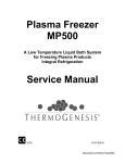
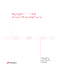
Overview
The ThermoGenesis Corp. MP1100 Freezer is a low temperature
freezing system. Blood components are frozen using a liquid
coolant which circulates around specially-designed pockets
containing the blood product. The MP1100 Freezer consists of the
following components (Figure 2-1):
MicroCascade ultra-low temperature condensing unit
Two (2) coolant circulating pumps
Deck and deck heater
Pockets
Pocket springs (P/N’s 8-1100-20/21/23 and 8-1101-20/21/23)
Primary and secondary power panels
Control panel
Figure 2-1: MP1100
Freezer
Control Arm
Chamber
Lids and
Deck
Drain Port
MP1100 Freezer – Operator and Maintenance Manual, 37-00-053.B
Control
Panel
Motor Box
Cover
Indicator
Light
Housing
2-3
Safety Devices
The Safety Thermostat
The MP1100 freezer consistently monitors the temperature of the
coolant with a temperature sensor and safety thermostat (see
Section InstaCoolant IV for a description of the coolant). If the
coolant temperature exceeds the safety thermostat temperature
setting, the thermostat turns off power to the major components
of the freezer, making the freezer inoperable. To adjust the safety
thermostat (see Section Safety Thermostat – Chapter 7).
Two situations can cause the safety thermostat to turn off
power to the major components of the freezer:
1. During equipment installation, when the coolant is added to
the freezer, it is most likely at room temperature or about
24ºC (75ºF). If the thermostat sensor detects the coolant is
above 27ºC (80ºF), it automatically shuts off power to the
major components of the freezer as a safety measure.
2. During a programmed defrost operation, the defrost heater
warms the coolant from its chilled temperature to about 3ºC–
5C (37ºF–41ºF). If the defrost heater does not shut off and
keeps warming the coolant, the safety thermostat will
automatically shut off power to the major components when
coolant reaches 27C (80F).
Major Components of the Freezer
Refrigeration System
The MP1100 Freezer is equipped with an ultra low temperature
refrigeration system.
Motor Box
Located at the right side of the freezer, the motor box contains
the two (2) coolant circulating pumps, electrical components,
safety thermostat, connection for the electrical defrost heating
element and the inlet/exhaust fans for cooling the motorbox
compartment.
Circulation Pumps
Located in the motor box compartment, the coolant circulating
pumps provide InstaCoolant IV to the freezing chambers during a
freeze cycle. Each pump runs independently of the other. If the
unit is not being used, the left pump motor will start if the
refrigeration comes on to circulate the coolant and maintain a
consistent temperature.
2-4
MP1100 Freezer – Operator and Maintenance Manual, 37-00-053.B
NOTE: In order to maintain a consistent temperature when the
condensing unit is on, the pump motor will start filling and
circulating coolant in the left chamber until set operating
temperature is reached. To remove or insert product during this
process, start a cycle in the right chamber.
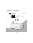
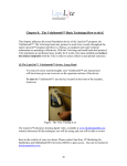
Deck and Pockets
The deck of the MP1100 Freezer is located under the two left-hand
lids and contains the pockets in which the blood products are
placed for freezing (Figures 2-2 – 2-5). The pockets are made of a
polyurethane material capable of maintaining flexibility at low
temperatures. The pockets hang down into the two chambers and
during a freezing cycle provide the enclosure for the blood
products during coolant circulation. The deck and pockets provide
a tight seal to insulate the low temperature reservoir from the
warmer room environment.
Figure 2-2: Deck for P/N
8-1100-20 and 8-1101-20
MP1100 Freezer – Operator and Maintenance Manual, 37-00-053.B
2-5
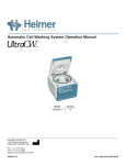
Figure 2-3: Deck for P/N
8-1100-21 and 8-1101-21
Figure 2-4: Deck for P/N
8-1100-23 and 8-1101-23
2-6
MP1100 Freezer – Operator and Maintenance Manual, 37-00-053.B
Figure 2-5: Deck for P/N
8-1100-27 and 8-1101-27
The Pocket Springs (available for P/N’s 8-1100-20/21/23
and 8-1101-20/21/23 only)
The pocket spring is a metal insert that acts as a stiffener for the
pocket and provides easy access for inserting and removing the bags
(Figure 2-6). The pocket spring adds tension to the pocket producing
a consistently flat, frozen bag, while decreasing freeze time.
Figure 2-6: Pocket spring
Freezing Chambers
Located below the deck are the two freezing chambers. During the
freezing cycle, these chambers are filled with low temperature
InstaCoolant IV that circulates around the pockets, freezing the
blood components.
MP1100 Freezer – Operator and Maintenance Manual, 37-00-053.B
2-7
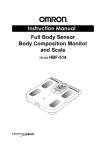
Power Panels
Located on the housing at the right end of the freezer, these panels
contain the electronics that operate the freezer (Figure 2-7). The
main power switch is located on the primary power panel and the
vacuum disable switch is located on the secondary power panel.
Fuses for the various electrical components are located in these
two panels.
Figure 2-7: Power panels
Primary Power Panel
Secondary Power
Panel
Control Panel
The control panel is located on the control arm (Figure 2-8). The
commands for operation, defrost, calibration and temperature
setpoint are entered using the keypads. Error messages are
shown on the temperature display.
Vacuum System (available for P/N’s 8-1100-27 and
8-1101-27 only)
The vacuum system expands the pocket to allow for easy insertion
of bottles.
2-8
MP1100 Freezer – Operator and Maintenance Manual, 37-00-053.B
Figure 2-8: Control arm
and control panel
Control Arm
Vacuum
Indicator Light
Temperature
Display
Keypad
Indicator Lights – Coolant Overtemperature Light
Located at the front, right end of the machine in the upper right
corner of the housing is a small red light. When lit, this light
indicates that the safety thermostat has shut off power to the
major components of the freezer due to high coolant temperature.
Indicator Lights – Vacuum Indicator Light
Located on top of the control panel is the vacuum indicator light.
This light (when not illuminated) indicates that the vacuum
system has been turned off or falls below 10” of vacuum. When
this light is illuminated, it indicates that the operator may load or
unload the blood components.
NOTE: The vacuum indicator light is activated only on P/N’s
8-1100-27 and 8-1101-27.
InstaCoolant IV
InstaCoolant IV is a silicone based heat transfer fluid specifically
designed for use in low temperature systems. While the fluid
operating range is -100ºC to 260ºC (-150ºF to 500ºF), the vapors
of the fluid have a flashpoint 1 at 42ºC (108ºF).
1
The lowest temperature at which the vapor of a combustible liquid can be made to ignite momentarily in air. This
assumes an ignition source is present such as a flame or electric heater element.
MP1100 Freezer – Operator and Maintenance Manual, 37-00-053.B
2-9
NOTE: ThermoGenesis Corp. provides a safety thermostat that
automatically shuts off power to the major components of the
freezer when the coolant temperature exceeds the safety
temperature setting. ThermoGenesis Corp. sets the safety
temperature limit at 27°C (80°F).
Installation, Service and Maintenance Forms
The forms shown in Appendix A are checklists designed to aid the
user in installation, service, and maintenance of the MP1100
Freezer.
2-10
MP1100 Freezer – Operator and Maintenance Manual, 37-00-053.B
Chapter
3
Installation
TABLE OF CONTENTS
Unpacking and Inspection .............................. 3-1
Connecting the Desiccant Filter Assembly —
P/N’s 8-1100-20/21/23 and
8-1101-20/21/23 only.......................................3-1
Connecting Desiccant Filter Assembly and Vacuum
Pump — P/N’s 8-1100-27 and
8-1101-27 only ....................................... 3-2
Placing the Freezer in Position ........................ 3-3
Electrical Installation and Specifications ........... 3-5
Installing the Control Arm and Control
Panel Housing ......................................... 3-5
Connecting all the Wires ................................ 3-7
Adding the InstaCoolant IV to the Freezer ........ 3-8
Removing and Replacing a Pocket —
P/N’s 8-1100-20/21/23 and
8-1101-20/21/23..................................... 3-8
Removing and Replacing a Pocket —
P/N’s 8-1100-27 and 8-1101-27 ................ 3-9
Adjusting the Safety Thermostat ................... 3-10
Starting the MP1100 Freezer ........................ 3-10
Temperature Pull-down................................ 3-11
Verifying Operating Temperature .................. 3-13
Unpacking and Inspection
Check for any shipping damage upon receiving the freezer. If
there is any apparent damage, notify the shipping company
immediately. Contact Helmer Technical Service if there are any
problems.
The following items are included with the freezer:
1
2
1
1
1
75 Gallons (284 liters) InstaCoolant IV
Spare Pockets
Control Panel Housing and Control Panel
Control Arm
Accessories Kit
NOTE: Each MP1100 requires 75 gallons of coolant. Coolant is
shipped in five boxes (22 gallons total) and one 55-gallon drum
containing 53 gallons.
Please record the following information from the back of the
freezer in the spaces marked below:
Part Number:
Serial Number:
Date of
Purchase:
Connecting the Desiccant Filter Assembly — P/N’s 8-1100-20/21/23
and 8-1101-20/21/23 only
The Desiccant Filter System on the MP1100 Freezer is located on
the back of the freezer. Before placing the freezer in position, it is
necessary to connect the desiccant filter tubing.
To connect the desiccant filter tubing:
1. Remove the plastic protective caps from the inlet and outlet of
the couplings attached to the desiccant filter.
2. Slide the tubing from the lid onto the inlet fitting on the
bottom coupling of the desiccant filter (Figure 3-1).
3. Slide the tubing from the chassis to the outlet fitting on top of
the coupling of the desiccant filter (Figure 3-1).
MP1100 Freezer – Operator and Service Manual, 37-00-053.B
3-1
Figure 3-1:
Desiccant Filter
assembly (control arm
and control panel not
installed)
}
Desiccant
Filter
Assembly
Connecting Desiccant Filter Assembly and Vacuum Pump —
P/N’s 8-1100-27 and 8-1101-27 only
The vacuum pump and the desiccant filter assembly on the
MP1100 Freezer are located on the back of the unit. Before placing
the freezer in position, it is necessary to connect these
assemblies. The vacuum pump assembly should be mounted on
the rear-upper-left of the freezer. The desiccant filter assembly
should be mounted on the rear, lower, right side of the freezer
(Figure 3-2).
To install vacuum pump assembly:
1. First, unscrew the four ¼-20x3/4 hex bolts from the rear of
the unit (hex bolts located next to the power junction box).
2. Next, position the vacuum pump into place – while aligning the
four ¼-20 tap holes. Torque the four ¼-20x3/4 hex bolts to 47
+/- 3 in-lb.
3. Plug vacuum pump connector to “pig-tail” connector on rear on
motor box cover assembly (left side).
4. The reinforced, spiral tubing coming out of the motor box
cover (from rear) should be assembled onto the “inlet” port of
the vacuum pump. Secure the tubing tightly with the supplied
adjustable clamp.
3-2
MP1100 Freezer – Operator and Service Manual, 37-00-053.B
Figure 3-2: Desiccant filter
and vacuum system
arrangement
Vacuum
System
Assembly
{
Desiccant
Filter
Assembly
{
To install desiccant filter assembly:
1. Unscrew the four #10x1 self-tapping screws from the rear of
the unit (screws located on the rear-lower –right of the unit).
2. With the desiccant filter clip on hand, thread self-tapping screw
through the hole of clip (1 screw / clip, total 4 times). Secure
the clip to rear of freezer unit, as depicted. Hand-tighten all
four desiccant clips into place.
3. Snap desiccant filter assembly onto clip.
4. With the supplied 50” long reinforced, spiral tubing, attach one
end to the inlet of the desiccant filter (the 1” PVC pipe location
beneath the gate valve). Secure tightly using the supplied
adjustable clamp.
5. Attach other end of tubing to the “outlet” port of the vacuum
pump. Again, secure tightly with one of the supplied adjustable
clamp.
6. Remove the plastic protective cap on the desiccant filter
assembly – exposing the barbed portion of the fitting. Attach
the free end of the clear flexible tubing (the one tubing in
conjunction with the lids) to the barbed portion of the fitting.
Placing the Freezer in Position
The MP1100 freezer must be located on a level floor. The freezer
must be located in a room where the ambient temperature is in
MP1100 Freezer – Operator and Service Manual, 37-00-053.B
3-3
the range of 15C to 26C (59F to 79F) with the condensing unit
running and the humidity is in the range of 10% to 60% RH.
Under no circumstances is the MP1100 to be located in an outside
environment (see Section Specifications – Chapter 2).
NOTE: This freezer puts out approximately 24,000 BTU heat
output while the condensing unit is operating. Use this heat output
specification, along with any other equipment in the room, when
calculating the amount air conditioning needed to conform to the
operating temperature requirements.
CAUTION: DO NOT add InstaCoolant IV to the freezer before
placing the freezer in its final location.
NOTE: For ease of movement and accessibility to the place of
location allow 4” (15 cm) clearance on both sides of the freezer
when passing through passageways and doorways.
NOTE: There must be at least 18” (46 cm) clearance from the
back and left side of the freezer to any wall to allow for adequate
ventilation. There must be 36” (91 cm) between the wall and right
side of the freezer to service the condensing unit. If adjacent
equipment is also putting out heat, additional space may be
required.
(For P/N’s 8-1100-27 and 8-1101-27) There needs to be enough
space to read the vacuum system gauge located on the back of
the freezer.
Contact Helmer Technical Service for assistance with additional
space requirements.
CAUTION: Make sure the Power Switch is in the OFF position
before connecting to the power supply.
Once the freezer is in position lower the leveling feet. There will
only be about 1/2” to level the unit with the feet. If more is
needed to level the unit, the unit may need to be relocated or call
Helmer Technical Service for help.
NOTE: Level the freezer, both side to side and front to back by
placing a level on the top of the freezer and adjusting the leveling
feet up or down.
3-4
MP1100 Freezer – Operator and Service Manual, 37-00-053.B
Electrical Installation and Specifications
A qualified electrician should wire the power source of the freezer.
The unit shall be wired directly to a minimum circuit plug of 50
amps or a 60 amp disconnect at the wall, by a qualified
technician. The electrician will need to supply an electrical line of
ten feet in length. This power cord will need to be colored as
follows:
USA, L1=Blue (Hot), L2=Brown (Hot), L3=Yellow/Green
(Ground)
Europe,
L1=Brown
(Hot),
L2=Blue
(Neutral),
L3=Yellow/Green (Ground)
The freezer requires a 50 amp dedicated circuit (See
Section Specifications – Chapter 2).
CAUTION: A qualified electrician must survey the existing power
availability to verify the electrical capabilities at your facility.
Installing the Control Arm and Control Panel Housing
The control panel housing for the MP1100 Freezer is located on a
control arm that holds the control panel at eye level for easy
viewing and can swivel out of the way to service the motor box
cover.
Install control arm and control panel by following the steps
below:
1. Remove the plastic wrap from the control arm.
2. Make sure the wiring bundle extends out each end of the
control arm.
3. At the back of the freezer, thread the wiring bundle through
the support and slide the control arm in place. Tighten the
setscrew of the support so that it engages the slot of the arm.
This will limit the throw of the control arm (Figure 3-3).
4. Unwrap the control panel housing, slide it on to the control arm
and tighten the setscrew to hold the control panel housing in
place (Figure 3-3).
MP1100 Freezer – Operator and Service Manual, 37-00-053.B
3-5
Figures 3-3, 3-4:
Control Arm Wiring
Detail
3-6
MP1100 Freezer – Operator and Service Manual, 37-00-053.B
Connecting all the Wires
Now that the control arm and control panel housing are in place,
the temperature probe wiring, control cable bundle, ground wire
and photo sensor cable can be connected.
1. Remove the screws holding the control panel in place in the
control panel housing (Figure 3-5).
2. Gently pry the control panel away from the control panel
housing and lay upside down in the control panel housing.
3. Connect the wires to the back of the control panel (Figure 3-5)
making sure that all ribbon connectors and cables are pressed
firmly in place.
4. Replace the control panel back in the housing and tighten the
screws in place (Figure 3-5).
5. At the rear of the freezer under the control arm support, remove
the screws holding the wiring cover in place, remove the cover
and connect the wiring (Figures 3-3, 3-4) making sure all ribbon
connectors and cables are pressed firmly in place.
6. Replace the wiring protective cover using the screws and
tighten the screws in place.
Figure 3-5: Control
Panel Wiring Detail
FRONT VIEW OF
CONTROL PANEL
REAR VIEW OF
CONTROL PANEL
SET SCREW
INDICATOR
LAMP CABLE
GROUND WIRES
MP1100 Freezer – Operator and Service Manual, 37-00-053.B
CONTROL CABLE
BUNDLE
3-7
Adding the InstaCoolant IV to the Freezer
The MP1100 uses 75 gallons of InstaCoolant IV silicone based
coolant. The coolant is added to the freezer in a 53-gallon (200.6liter) drum and small 4.5-gallon (9.5-liter) containers using the
following method:
1. Remove a pocket in the left hand chamber closest to the left
side of the chamber.
2. Insert the hose from the transfer pump through the pocket
opening.
3. Add the coolant to the freezer until the level is about 2.5”
(6.35 cm) above the bottom of each chamber.
NOTE: When coolant is added, wait two minutes before checking
coolant level in each chamber.
CAUTION: InstaCoolant IV should be stored in a room where the
temperature does not exceed 85°F (29.4°C). Never store
InstaCoolant IV in direct sunlight.
Removing and Replacing a Pocket — P/N’s 8-1100-20/21/23 and
8-1101-20/21/23
Removing a pocket
1. Remove the pocket spring by reaching in the pocket and
grasping the ends and pressing them slightly together as the
spring is removed (Figure 3-6).
Figure 3-6: Pocket Springs
Protective
Caps
Pocket
Spring
Pocket
3-8
MP1100 Freezer – Operator and Service Manual, 37-00-053.B
2. Grab the inside front seam of the pocket approximately one
inch (2.5 cm) below the snap seal ring.
3. Lift up to pop the snap seal ring loose from the deck lip.
4. Remove the pocket.
Replacing a pocket
1. Holding the top of the pocket, push the new pocket through
the opening in the deck.
2. Seams of the pocket should always be aligned toward the front
and rear of the freezer.
3. Place the snap seal ring onto the deck lip.
4. Press the snap seal ring into place on the deck lip. Starting at
the front seam, work around both sides of the snap ring, going
toward the opposite side.
5. If using pocket springs, remember to replace them. Make sure
the pocket spring is firmly in place under the snap seal of the
pocket, and the protective caps are on the ends of the spring
(Figure 3-6).
CAUTION: The protective caps must remain on the ends of the
spring when in use. Failure to do so will compromise the integrity
of the pocket.
6. When the pocket spring is in place, the tips of the pocket spring
should press against the ends of the pocket under the deck.
7. Close lid.
Removing and Replacing a Pocket — P/N’s 8-1100-27 and 8-1101-27
Removing a pocket
Each pocket has two seams down the sides and a clip at the
bottom. The clip holds the pocket to the rod at the bottom of the
freezing chamber. The top of the pocket has a snap seal ring
which is used to attach it to the deck.
1. Turn off the vacuum disable switch on the secondary power
panel.
2. Grab the inside front seam of the pocket approximately one
inch (2.5 cm) below the snap seal ring.
3. Lift up to pop the snap seal ring loose from the deck lip.
4. Holding the pocket, push the pocket down below the deck and
reach into the chamber. Grab the clip at the bottom of the
pocket and twist to detach it from the rod.
MP1100 Freezer – Operator and Service Manual, 37-00-053.B
3-9
CAUTION: Use care when removing the pockets. Placing hands in
coolant when coolant temperature is below freezing can cause
frostbite.
5. Remove the pocket.
Replacing a pocket
1. Holding the top of the pocket, push the new pocket through
the opening in the deck.
2. Attach the clip located on the bottom of the pocket to the rod
located at the bottom of the chamber by twisting the clip until
it locks onto the rod.
3. Bring the top of the pocket up through the opening in the
deck, being careful not to twist the pocket. Seams of the
pocket should always be aligned toward the front and rear of
the freezer.
4. Place the snap seal ring onto the deck lip.
5. Press the snap seal ring into place on the deck lip. Starting at
the side seam, work around both sides of the snap seal ring,
going toward the opposite side.
6. Close lid and turn vacuum disable switch back on.
Adjusting the Safety Thermostat
The safety thermostat is a safety feature which is set at the
factory to 80F. Though InstaCoolant is usually stored at room
temperature (75F to 85F (24C to 29C)). If the freezer detects a
coolant temperature of greater than 80F, the red indicator light
would be illuminated and the safety thermostat would need to be
temporarily adjusted. Call Helmer Technical Service for assistance
with adjusting the safety thermostat.
CAUTION: Only a trained service technician should adjust the
safety thermostat.
Starting the MP1100 Freezer
1. Make sure the unit is properly connected to power supply, then
turn on the power switch.
3-10
MP1100 Freezer – Operator and Service Manual, 37-00-053.B
NOTE: There is a built-in 2 to 5 minute time delay once the power
is turned on before the high-stage compressor turns on, along
with the condenser cooling fans. Thirty seconds after the high
stage compressor starts, the low stage compressor will start.
2. After the MicroCascade refrigeration system starts, the
MP1100 Freezer will begin to chill the InstaCoolant to the set
operating temperature.
Temperature Pull-down
At the start of the temperature pull-down it is
recommended to do the following:
1. Record the temperature on the display at the beginning of the
pull-down.
NOTE: Record the temperature approximately every 10 minutes
as the unit drops in temperature, to verify proper operation.
NOTE: During temperature pull-down it is necessary to run all
chambers in continuous 90-minute freeze cycles to circulate the
coolant.
Initiate a freeze cycle by doing the following:
1. Set a 90-minute freeze cycle in both chambers.
2. On each keypad press RESET.
3. Then enter “9000”.
4. Press START within 10 seconds to confirm the selection
5. Check to make sure the display reads “9000” for a 90-Minute
freeze cycle.
6. Begin a freeze cycle by pressing START again.
7. Then control panel will show “FILL” and the after 1-minute
the timer will start to count down in seconds.
8. By running a freeze cycle during the temperature pull-down the
coolant is continuously circulated resulting in a faster pull-down.
9. Run subsequent freeze cycles until the unit has reached
operating temperature. Once the unit has reached operating
temperature and the MicroCasade Condensing Unit has
turned off, terminate the freeze cycle by pressing
STOP/CLEAR.
10. The control panel will show ”DRN“ (for drain) for 1-minute.
Then at the end of the drain cycle, the display will show
“INT”, press STOP/CLEAR again to reset the display for the
next freeze cycle.
MP1100 Freezer – Operator and Service Manual, 37-00-053.B
3-11
11. (For P/N’s 8-1100-27 and 8-1101-27 only) Open lid and check
vacuum system gauge on the back of the freezer (Figure 3-7).
Figure 3-7: Vacuum
system gauge
Vacuum
Gauge
The required operational vacuum range is 10-12 inches
vacuum. If the vacuum gauge reading is more or less than 1012 inches vacuum, the vacuum system needs adjustment. To
increase vacuum, turn the red knob between the desiccant
tubes counterclockwise. To decrease vacuum, turn the red
knob clockwise (Figure 3-8).
3-12
MP1100 Freezer – Operator and Service Manual, 37-00-053.B
Figure 3-8:
Desiccant Tube
Assembly
Knob
Verifying Operating Temperature
After the freezer has reached the operating temperature, verify
the temperature by following the steps listed in Section
Verification of Operating Temperature – Chapter 4. After this
verification, the MP1100 is now ready for validation and operation.
MP1100 Freezer – Operator and Service Manual, 37-00-053.B
3-13
Chapter
4
Operating
Instructions
TABLE OF CONTENTS
Introduction .................................................. 4-1
Factors Influencing Plasma Freeze Times........... 4-2
Operational Input Codes ................................. 4-2
Setting the Operating Temperature .................. 4-3
Verifying Operating Temperature Calibration...... 4-4
Recalibrating the Operating Temperature .......... 4-4
Setting the Freeze Cycle Time.......................... 4-5
Running the Freeze Cycle................................ 4-6
Running the Night Cycle.................................. 4-7
Introduction
NOTE: In order to maintain a consistent temperature when the
condensing unit is on, the pump motor will start filling and
circulating coolant in the left chamber until set operating
temperature is reached. To remove or insert product during this
process, start a cycle in the right chamber.
This chapter outlines the following operations of the freezer using
the Control Panel Keypads (Figure 4-1):
The MP1100 Freezer is easy to adjust and to operate. This section
outlines the following basic operations of the freezer using the
control panel keypads.
Setting the operating temperature
Verifying the operating temperature calibration
Calibrating the operating temperature
Setting the freeze cycle time
Running a freeze cycle
Running a defrost cycle
Setting the MP1100 freezer for Night Cycle operation
Figure 4-1: MP1100
Control Panel
MP1100 Freezer – Operator and Service Manual, 37-00-053.B
4-1
Factors Influencing Plasma Freeze Times
There are a number of variables which could influence the time it
takes to freeze plasma in the MP1100. As additional variables are
added to the freeze process, the time to freeze plasma solid may
be extended.
Known factors which influence freeze time:
Higher volume of plasma in the bag
Greater number of bags per freeze cycle
Larger size of the collection bag
Folding plasma bags during freeze
Use of overwrap bags during freeze
Use of transport boxes during freeze
Attached satellite bags during freezing
Orientation of plasma bag in the pocket that allows part of
the bag to be above the coolant level
Lower coolant temperature
Ambient operating temperature
NOTE: Please take into account
determining your freeze cycle time.
the
above
variables
when
Operational Input Codes
The following codes are programmed to perform various functions
with the freezers. Enter the codes using the keypad on the control
panel. Codes are entered using the following sequence:
[CODE] RESET [DESIRED FUNCTION] START
For example, to set the operating temperature to -42C, the
operator would enter “100”, press RESET, enter “42” (for -42C)
and press START within 10 seconds to save the instructions.
For example, to set the freeze cycle time, press RESET. The
time/function display will flash the current freeze cycle time (i.e. –
“1230” for 12 minutes, 30 seconds). Enter the desired freeze cycle
time and press START to save the new cycle time.
NOTE: Press START within 10 seconds to save instructions;
otherwise, the MP1100 will default to the previous setting.
4-2
MP1100 Freezer – Operator and Service Manual, 37-00-053.B
CODE
FUNCTION
100
Set operating temperature
200
Set calibrated operating temperature
300
Nite cycle operation
400
Defrost cycle
RESET
Set or reset freeze cycle time
START
Begins freeze cycle and/or loads commands
to memory
STOP/CLEAR
Interrupts or cancels a function
Setting the Operating Temperature
The operating temperature is the set temperature of the
InstaCoolant IV during normal freezer operation. During a freeze
cycle, the coolant temperature may rise a few degrees for a period
of time as it absorbs the heat from the blood product. The MP1100
Freezer software allows the user to set the operating temperature
from -25°C to -55°C.
The following steps will guide you through adjusting the
operating temperature to the desired setpoint:
1. Enter 100 on a numeric keypad.
2. Press the RESET key.
3. The current operating temperature setting will flash on the
operating temperature display.
4. Enter the desired operating temperature on the keypad. For
example, enter 42 to set the operating temperature to -42°C.
The new temperature is displayed on the keypad. The temperature
range to be entered must be between -25C and -55C.
a) To erase any entry, press the RESET key.
b) To exit without saving, press the STOP/CLEAR key.
5. To save the new setting, press the START key within 10
seconds of the entry.
6. The coolant operating temperature is now set.
The coolant operating temperature is now set. To change the
setpoint for the coolant operating temperature at any time, repeat
steps 1 through 5 above.
MP1100 Freezer – Operator and Service Manual, 37-00-053.B
4-3
Verifying Operating Temperature Calibration
Verifying the operating temperature of the freezer confirms that
the digital temperature display is reading the actual coolant
temperature around the pocket. ThermoGenesis Corp. calibrates
the operating temperature of the freezer at the factory before
shipment. Verification (and re-calibration if required) should be
performed in the following instances:
quarterly maintenance
after relocation of the freezer
if freezer has been turned off for a period of time.
To verify the temperature calibration:
1. The temperature of a freeze cycle must be measured.
2. Lift the lid on a chamber. The display will display “LID” /
“OPEN”.
3. Insert a calibrated thermometer (capable of reading to -60°C)
into a middle pocket of the chamber corresponding to the
keypad being used.
4. Close the lid.
5. Enter 300 reset on the corresponding keypad to initiate the
freeze cycle. The chamber will fill and “NITE” will flash on the
display.
6. After four minutes lift the lid. Keeping the thermometer close
to the pocket, read and record the temperature. This will help
to prevent false reading due to exposure to ambient
temperature. Remove the thermometer from the pocket and
close the lid. Press STOP on the keypad and the chamber will
drain.
7. If the recorded temperature of the thermometer is not ±3°C
from the temperature displayed on the control panel, the
freezer operating temperature should be recalibrated (see
below).
Recalibrating the Operating Temperature
1.
2.
3.
4.
4-4
To recalibrate the temperature, enter 200 on an idle keypad.
Press the RESET key.
The temperature display will flash “00”.
On the keypad, enter the temperature obtained from the
thermometer. The new temperature will be displayed. For
example, if the calibrated thermometer reading was -35ºC and
the display showed -42ºC, enter 35 to set the operating
temperature to the calibrated temperature.
a) To exit without saving, press the STOP/CLEAR key.
MP1100 Freezer – Operator and Service Manual, 37-00-053.B
b) To erase any entry and start over, press the RESET
key.
5. Press the START key within 10 seconds to save the new
setting. The new setting will flash on the display panel for 10
seconds.
6. The operating temperature is calibrated. To recalibrate the
operating temperature at anytime repeat the steps above.
Setting the Freeze Cycle Time
The freeze cycle time can be adjusted from 1 second to 99
minutes and 59 seconds, depending upon the user’s requirements.
It is important to follow the validation requirements set by your
company to determine the freeze time required to produce the
desired final core temperature of the product.
Perform the following steps to set the freeze cycle time:
NOTE: Setting the time on one keypad does not affect the setting
on the other keypad.
1. Press the RESET key on the keypad corresponding to the
freezing chamber being used. The chamber must be idle and
the lid closed.
2. The current cycle time will flash on the display. The default is
90 minutes.
3. Enter the desired cycle time on the keypad. The new time is
displayed (non-flashing) on the display. For example, enter
3000 to set the time to 30 minutes and 00 seconds. The
maximum time that can be entered is 99 minutes and 59
seconds.
a) To erase an entry and start over, press the RESET
key.
b) To exit without saving, press the STOP/CLEAR key.
4. Press the START key within 10 seconds to save the new
setting. The new setting will be displayed.
5. The new freeze cycle time is now set. To change the freeze
cycle time for another chamber, repeat the steps listed above
on the appropriate keypad. Each chamber can have different
freeze cycle times depending on customer requirements.
MP1100 Freezer – Operator and Service Manual, 37-00-053.B
4-5
Running the Freeze Cycle
NOTE: Load right freezing chamber first and begin freeze cycle
before loading product into left chamber and starting a freeze
cycle in the left chamber.
Perform the following steps to run a freeze cycle on the
MP1100:
1. Open a lid. The corresponding display will alternate between
“LID” and “OPEN”.
2. Place blood components in the pockets.
CAUTION: To prevent pocket damage, do not drop or force blood
components in the pockets. If the unit has a vacuum system, wait
until the vacuum light is ON before loading or unloading the unit
with blood components.
3. Close the lid and press START. The control panel will flash
"FILL" for one minute, indicating that coolant is filling the
chamber.
4. Once the chamber is full, the corresponding display will begin a
countdown.
CAUTION: Unless absolutely necessary, do not raise the lid
during the freeze cycle. Do not add blood components at any time
during the freeze cycle without restarting the freeze cycle from the
beginning, as this will result in those blood components being
incompletely frozen.
5. If the lid is opened during the countdown, the chamber will
drain, the display will flash “DRN ”, and then a 5-second
alarm will sound. After the lid is closed, the chamber will fill,
the display will flash “FILL”, and then the freeze cycle will
resume at the point before the lid was opened.
6. During the freeze cycle, the countdown is displayed on the
control panel.
a) To stop the cycle, press STOP/CLEAR. The chamber
will drain, the display will flash “DRN ”, an alarm
will sound and “INT ” will flash on the control panel.
b) Press STOP/CLEAR again to restart freezing cycle or
press START and freezer will resume at the point
that the cycle was interrupted.
4-6
MP1100 Freezer – Operator and Service Manual, 37-00-053.B
7. The freeze cycle is complete when the countdown on the
Time/Function Display reaches “0”. The control panel will display
“DRN ”.
8. When the 75-second drain cycle is completed, an alarm will
sound.
9. Lift the lid. While the lid is open, the display will alternate
between “LID” and “OPEN”.
10. Remove the frozen blood components from the pockets.
CAUTION: To reduce the possibility of damaging the pockets,
slowly remove product from pockets.
Running the Night Cycle
NOTE: ThermoGenesis Corp. recommends running the MP1100 in
night cycle mode if unit is not being used for more than a 24-hour
period, such as weekends or holidays. The night cycle prevents
temperature variances when the unit is not being used to freeze
blood components.
The night cycle operation allows the user to place a load of blood
components in a chamber (or all chambers) before leaving for the
night or a weekend. When the night cycle is activated, the unit
performs a normal freeze cycle for the length of time last set on
the control panel. Upon completion of the freeze cycle, the freezer
will then cycle the pumps for five minutes every half-hour to
maintain the temperature of the frozen blood components.
Perform the following steps to run a night cycle:
1. Open the lid to an idle chamber and place the blood
components in the pockets. The corresponding keypad will
alternate between “LID” and “OPEN”.
2. Close the lid. The display will change back to the cycle time.
3. Enter 300 on keypad corresponding to the chamber where the
blood components have been loaded.
4. Press RESET. The corresponding display will flash “NITE”.
5. The night cycle is in operation. While the pumps are running,
the display will flash “NITE ” and when the pumps are not
running, “NITE ” will not flash.
6. The user can return to normal operating mode by simply
pressing the STOP/CLEAR button on the keypad.
7. To run a night cycle in more than one chamber, repeat these
steps on each keypad corresponding to the chamber being used.
MP1100 Freezer – Operator and Service Manual, 37-00-053.B
4-7
Chapter
5
Maintenance
TABLE OF CONTENTS
Maintenance Schedule ....................................5-1
Checking and Cleaning the Pockets...................5-1
Cleaning the Deck ..........................................5-2
Removing and Replacing a Pocket —
P/N’s 8-1100-20/21/23 and
8-1101-20/21/23......................................5-2
Removing and Replacing a Pocket —
P/N’s 8-1100-27 and 8-1101-27 .................5-3
Repairing a Pocket .........................................5-4
Cleaning the Freezer ......................................5-5
Checking the Desiccant Filters .........................5-5
Checking the Pump Motor Cooling Fans .............5-5
Checking the Coolant Level .............................5-6
Checking the Lid Gasket Seals .........................5-6
Checking the Hinges.......................................5-6
Checking the Deck Screws ..............................5-7
Verifying Operating Temperature Calibration......5-7
The Defrost Cycle ..........................................5-7
Before Starting the Defrost Cycle .....................5-7
Initiating the Defrost Cycle..............................5-8
Draining Water from the System ......................5-9
Restoring Freezer to Operating Temperature ..... 5-10
Maintaining the Refrigeration System.............. 5-10
The following are the minimum recommended maintenance
periods. Maintenance may be performed more frequently if
required. Forms are included in Appendix A of this Manual. The
table below outlines the maintenance schedules to be performed
by the blood center. The sections following the table provide detail
for the routine maintenance schedules listed.
Maintenance Schedule
SCHEDULE
MAINTENANCE DESCRIPTION
Daily
Clean the deck
Check and clean or repair the pockets
(repair or replace if necessary)
Weekly
Clean the unit
Monthly
Check desiccant filters
Check motor box cooling fans
Check vacuum gauge (P/N’s 8-1100-27
and 8-1101-27)
Quarterly
Check coolant level
Check lid gasket seals
Check hinges
Check deck screws
Verify operating temperature calibration
Defrost the freezer
Bi-annual
Maintain the refrigeration system
Checking and Cleaning Pockets
NOTE: If there is a blood component leak, dispose
biohazardous waste in a biohazardous waste container
accordance with local and national regulations.
of
in
1. (For P/N’s 8-1100-27 and 8-1101-27) Before using the
vacuum gauge, the vacuum light needs to be illuminated. If
the light is not working, see Section Troubleshooting – Chapter
6. Check the pockets for leaks using the vacuum test gauge
provided with the freezer. Insert foam part of test gauge into
each pocket. If the gauge registers any value greater than 0,
the pocket has a leak and needs to be repaired or replaced. If
not immediately replaced, a pocket plug can be inserted into
the pocket opening temporarily.
MP1100 Freezer – Operator and Service Manual, 37-00-053. B
5-1
CAUTION: Do not vacuum out the coolant.
2. If coolant is inside the pocket, it also indicates a leak. Repair
or replace the pocket.
3. If ice or frost is inside the pocket, remove the ice or frost with
a small, wet/dry vacuum cleaner.
4. Dry the lids and deck with a soft cloth and close the lids.
Cleaning the Deck
1. Raise both lids allowing ice to melt off the deck (approximately
15-20 minutes).
2. Once ice is melted, use a wet/dry vacuum cleaner or soft cloth
to remove water from the deck and around the pockets.
Removing and Replacing a Pocket — P/N’s 8-1100-20/21/23 and
8-1101-20/21/23
Removing a pocket
Remove the pocket spring by reaching in the pocket and grasping
the ends and pressing them slightly together as the spring is
removed (Figure 5-1).
Figure 5-1: Pocket springs
Protective
Caps
Pocket
Spring
Pocket
1. Grab the inside front seam of the pocket approximately 1 inch
(2.5 cm) below the snap seal ring.
5-2
MP1100 Freezer – Operator and Service Manual, 37-00-053,B
2. Lift up to pop the snap seal ring loose from the deck lip.
3. Remove the pocket.
Replacing a pocket
1. Holding the top of the pocket, push the new pocket through
the opening in the deck.
2. Seams of the pocket should always be aligned toward the front
and rear of the freezer.
3. Place the snap seal ring onto the deck lip.
4. Press the snap seal ring into place on the deck lip. Starting at
the front seam, work around both sides of the snap ring, going
toward the opposite side.
5. Replace pocket springs and ensure that black protective caps
are firmly seated on spring before placing into pockets (Figure
5-1).
6. Close lid.
Removing and Replacing a Pocket — P/N’s 8-1100-27 and 8-1101-27
Removing a pocket
Each pocket has two seams down the sides and a clip at the
bottom. The clip holds the pocket to the rod at the bottom of the
freezing chamber. The top of the pocket has a snap seal ring
which is used to attach it to the deck.
1. Turn off the vacuum disable switch on the secondary power
panel.
2. Grab the inside front seam of the pocket approximately 1 inch
(2.5 cm) below the snap seal ring.
3. Lift up to pop the snap seal ring loose from the deck lip.
4. Holding the pocket, push the pocket down below the deck and
reach into the chamber. Grab the clip at the bottom of the
pocket and twist to detach it from the rod.
CAUTION: Use care when removing the pockets. Placing hands in
coolant when coolant temperature is below freezing can cause
frostbite.
5. Remove the pocket.
Replacing a pocket (models 8-1100/1101-27):
1. Holding the top of the pocket, push the new pocket through
the opening in the deck.
2. Attach the clip located on the bottom of the pocket to the rod
located at the bottom of the chamber by twisting the clip until
it locks onto the rod.
MP1100 Freezer – Operator and Service Manual, 37-00-053. B
5-3
3. Bring the top of the pocket up through the opening in the
deck, being careful not to twist the pocket. Seams of the
pocket should always be aligned toward the front and rear of
the freezer.
4. Place the snap seal ring onto the deck lip.
5. Press the snap seal ring into place on the deck lip. Starting at
the side seam, work around both sides of the snap seal ring,
going toward the opposite side.
6. Close lid and turn vacuum disable switch back on.
Repairing a Pocket
CAUTION: Wear protective gloves and use safety precautions. If
repairing pocket during a decontamination procedure, follow
biohazardous precautions.
1. Use the pocket repair kit that comes with the freezer (See
Section Unpacking and Inspection – Chapter 3), a cotton swab
and a disposable cup.
2. Remove the leaking pocket (see previous Section Removing
and Replacing a Pocket). Use soft cloth to remove coolant from
pocket.
3. Locate the hole visually or by filling the pocket with water and
watching for leaks.
NOTE: The pocket repair kit is designed for repair of small holes,
not for tears along the seam or around the snap seal ring.
4. Make sure the surface of the pocket to be patched is dry.
Place a small amount of repair kit tape on the inside of the
pocket covering the hole.
5. Clean 1 cm around the hole by applying a small amount of
Cotol-240 with the cotton swab to the outside of the pocket.
6. In the disposable cup, mix equal amounts of Cotol-240 and
Aquaseal using the wooden stir stick. The consistency should
be like liquid glue.
7. Apply a coating of this mixture onto the hole overlapping 1 cm
around the hole.
8. Let dry for a full 2 hours. Test the repaired pocket for leaks by
following step 3. If there is no leak, then pocket is ready to
use. If there is a leak, repeat the repair procedure (steps 4
through 8). Re-test for leaks before use.
5-4
MP1100 Freezer – Operator and Service Manual, 37-00-053,B
9. A repaired pocket should be used as an interim solution. A
repaired pocket should be replaced with a new pocket.
NOTE: Place the opened container of Aquaseal in the refrigerator
for later pocket repairs. Once mixed, Cotol-240 and Aquaseal can
be used until the glue becomes thick.
Cleaning the Freezer
On a weekly basis, clean the freezer. Using a mild detergent in
warm water, wipe all outer surfaces, the control panel, the inner
surfaces of the lid and gasket and the deck.
Checking Desiccant Filters
The desiccant filter tube(s) are located on the back of the freezer
(Figures 3-1, 3-2). The blue indicating pellets in the desiccant
material need to be replaced when all the blue pellets fade to a
gray color.
To replace desiccant material:
1. Unsnap the clips holding the tube and remove the tube of
desiccant.
2. Remove the top coupling on the desiccant filter that holds the
desiccant beads.
3. Dispose of contents according to local regulations.
4. Fill clear tubes completely with new desiccant (P/N 7-01-038).
5. Replace top coupling and tighten.
6. Place the tube back into the clamps and snap closed.
7. Repeat for the other desiccant tube (P/N’s 8-1100-27 and
8-1101-27).
8. Verify proper tubing connection or inlet and outlet of tubes.
Checking the Pump Motor Cooling Fans
1. Hold a piece of paper against the intake fans on the right side
of the motor box cover. The paper should be drawn into the
fans indicating a good airflow.
2. Hold a piece of paper against the exhaust fans at the back of
the motor box cover. The paper should be blown away from
the cover.
3. If there is no airflow, turn the freezer off immediately and
contact Helmer Technical Service.
MP1100 Freezer – Operator and Service Manual, 37-00-053. B
5-5
Checking the Coolant Level
NOTE: Coolant level should only be checked with freezer at
operating temperature with none of the chambers running.
1. No chambers should be in use and it should be at least 5
minutes from the last freeze cycle.
2. Open a lid and remove one of the front pockets.
3. Look down into the chamber. The coolant level should be
about 2.5” (63.5 mm) above the bottom of the chamber. Use a
ruler or other measuring device to check the level.
4. Add coolant if level is less than 2.5” (63.5 mm). Pour coolant
into the chamber through the removed pocket opening using a
funnel until coolant level is at 2.5” (63.5 mm).
5. Replace the pocket and close the lid.
Checking the Lid Gasket Seals
1. All lids should be closed.
2. Visually inspect to make sure there are no gaps between the
lid and the gasket and the deck.
3. If a gap is found, then check hinges on the appropriate lid to
make sure the hinge is not loose. If hinge is loose, adjust hinge
until seal is restored. If hinge is not loose, replace the gasket
seal.
NOTE: A tight seal reduces water from entering into the unit,
reducing ice build-up on deck and in coolant.
Checking the Hinges
1. Open the lids. Lids should remain open.
2. Visually inspect the hinges for damage. Grasp either side of
the hinge and gently move hinge side-to-side and up-anddown. If hinges are loose, they will move during this test. If
hinges are loose, re-seat lid (if necessary) and tighten
appropriate hinge screws. Repeat test until no hinge
movement is detected.
3. Close lids and inspect them to make sure there is no gap
between the lid and gasket.
5-6
MP1100 Freezer – Operator and Service Manual, 37-00-053,B
Checking the Deck Screws
1. Open both lids.
2. Inspect the deck to ensure that all screws are tight. Tighten
the screws if needed.
Verifying the Operating Temperature Calibration
See Section Verifying Operating Temperature – Chapter 4.
The Defrost Cycle
Factors that may influence the need for defrost are:
Operation of the freezer in a high humidity environment
Improperly sealed pockets. When this happens, moisture in
the air condenses and turns to ice. Ice buildup in the reservoir
will eventually clog the pump inlets and cause improper filling,
resulting in unfrozen product. Ice buildup can also cause pump
breakage and costly repairs.
NOTE: THERMOGENESIS CORP. recommends, as a minimum,
defrosting the freezer every 90 days. If humidity in the room
where the freezer is located is higher than the specified humidity
range or the freezer pockets have not been properly maintained,
the freezer may require more frequent defrost and filter cycles.
NOTE: The MP1100 is equipped with an electric defrost heater to
aid in warming up the coolant.
The following steps will guide the user through the defrost cycle
procedure.
Before Starting the Defrost Cycle
There are two items to verify before starting a defrost cycle. Non
compliance of either of these may cause the sensing bulb of the
safety thermostat to be exposed above the coolant and cause the
termination of the defrost cycle. As a result of the termination of
the cycle, the control panel will go black. The system will
automatically return to the refrigeration cycle (the control panel
will reinitiate just as though the user had turned off, then turned
MP1100 Freezer – Operator and Service Manual, 37-00-053. B
5-7
on, the freezer). The unit will start to pull-down to set operating
temperature.
1. It is important to make sure that the freezer is level, both
front-to-back, and side-to-side.
2. The coolant level in each chamber should be about 2.5” (63.5
mm) above the bottom of the chamber when the unit is at
rest. There must be sufficient coolant in the freezer.
WARNING–FIRE DANGER: DO NOT place an electric immersion
heater in the coolant. (see Section Safety Precautions – Chapter 1).
Initiating the Defrost Cycle
1. Loosen a pocket and place 4 to 6 drops of dye (located in the
Accessories Kit) in either chamber.
2. To start the defrost cycle, enter 400 on one of the numeric
keypads, then press RESET. This closes the refrigerant liquid
line solenoid valve, shutting off refrigeration to the freezer. At
the same time, the pumps begin circulating the coolant
through the chambers, and the defrost heater is engaged to
warm up the coolant to 3ºC–5ºC (37ºF–41ºF). The MP1100
Freezer will take 6–10 hours (depending on operating
temperature) to warm the coolant to termination temperature.
3. Once the defrost warm-up cycle completes and shuts off the
pumps, allow the unit to sit for about 5 minutes (this will allow
the water in the system to settle) turn the power switch on the
freezer to the OFF position.
4. For P/N’s 8-1100-27 and 8-1101-27, before the defrost cycle
completes the warming of the coolant (to about +2°C),
remove the pockets from the front and back of each chamber.
(For P/N’s 8-1100-20/21/23 and 8-1101-20/21/23), simply
open the lip of the pocket.
NOTE: Since the pumps are still running, they will circulate the
dye throughout the reservoir and the chamber(s) allowing any
water in the freezer to absorb the coloring.
5. While still facing the primary power panel, remove the 4
screws holding the primary power panel in place and gently
slide the primary power panel out of the console.
6. Remove the solenoid fuse from the fuse holder marked
SOLENOID or the wire connector next to the fuse holder
marked solenoid coil.
5-8
MP1100 Freezer – Operator and Service Manual, 37-00-053,B
7. Replace the primary power panel in the console and secure
with the four screws.
Draining the Water from the System
1. Make sure that pockets at the front and back of the chambers
are removed to allow access to the bottom of the chambers for
removal of any water collected there.
2. Make sure that you have a 5-gallon pail and the hand pump
(located in the Accessories Kit).
3. Take the hand pump and carefully skim any colored water
residing on top of the coolant which is in the bottom of each
chamber.
4. Once the chambers are cleared of any collected water, turn the
power switch to the ON position, start the pumps again, and
run for a period of 15 minutes. This will deposit more water
into the chambers.
5. After shutting off the pumps, allow the unit to sit for a period
of 5 minutes to allow the water to settle in the chambers.
6. Repeat Steps 1 through 4 until no colored water is seen in the
chambers. Then turn the Freezer Power switch to the OFF
position.
7. Remove the small black port cover on the drain port of the
freezer (located on left hand side of freezer in upper right hand
corner). Attach the hand pump to the drain port.
8. Pump fluid until it becomes clear, then run pump for 15
minutes. Allow fluid to sit 5 minutes, then pump again. If no
colored water comes out, then the water has been drained. If
not, then repeat this process again.
9. Remove the hand pump from the drain port and replace the
small black port cover on the drain port.
10. Allow the fluid in the 5-gallon pail to settle for about 5
minutes. Place the pail into a walk-in freezer. In approximately
one hour, the water will freeze, but the coolant will not freeze.
This will separate the water from any coolant in the pail.
Properly dispose of the colored water. Pour the remaining
coolant into the unit (see previous Section Checking the
Coolant Level). Store the hand pump to prevent damage or loss;
you will need the hand pump for future use in defrost cycles.
NOTE: Freeze pail overnight. Remove ice and pour coolant back
into the freezer.
MP1100 Freezer – Operator and Service Manual, 37-00-053. B
5-9
Restoring Freezer to Operating Temperature
1. Replace all pockets removed in the defrost process to their
proper positions, making sure the snap-seals are firmly in
place. Also, check all the pockets for tears or holes.
NOTE: Remember that improperly sealed, or torn pockets allow
moisture to enter the freezer chamber. This moisture enters the
system quickly when the freezer is down to operating temperature
contributing to ice build up and resulting in the need for more
frequent defrost.
2. While facing the primary power panel, remove the 4 screws
holding the primary power panel in place and gently slide the
primary power panel out of the console.
3. Replace the solenoid fuse in the fuse holder marked SOLENOID
and/or the wire connector and verify that the fuse holder is
securely refastened.
4. Replace the primary power panel in the console and secure
with the four screws.
5. The refrigeration will start and the system will begin to cool
down to the set operating temperature (-25ºC to -55ºC or
-32ºF to -67ºF). Remember, there is a programmed 2–5
minute delay after the defrost cycle is terminated, prior to the
refrigeration system start up.
6. Set freeze cycle times on both keypads for 90 minutes and run
continuous freeze cycles to circulate coolant until the unit is
down to the set operating temperature.
7. After unit comes down to temperature, check the coolant level.
8. Verify operating temperature calibration and calibrate as
needed (see Section Calibrating the Operating Temperature –
Chapter 4).
Maintaining the Refrigeration System
1. Turn the power switch on the right side of the freezer to OFF.
2. Remove the screws holding the grille on the front of the
condensing unit section of the freezer.
3. Remove the grille and carefully place it next to the freezer. The
inlet side of the refrigeration condenser coil is now visible.
4. Using a soft vacuum brush, vacuum any dust and dirt off the
fins of the condenser coil, being careful not to bend any of the
fins on the coil. Then, vacuum the grille.
5-10
MP1100 Freezer – Operator and Service Manual, 37-00-053,B
Chapter
6
Troubleshooting
TABLE OF CONTENTS
Introduction .................................................. 6-1
No Power to Unit............................................ 6-2
Freezer Display is Lit, but Pumps Do Not Work ... 6-2
Coolant Chamber Fills Initially, but During
the Cycle the Coolant Level Drops Off ........ 6-2
Product is not Completely Frozen ..................... 6-2
Coolant Temperature is too High ...................... 6-3
Condensing Unit (Refrigerant System)
Shuts Down............................................ 6-3
Pockets Tearing or Ripping .............................. 6-3
Vacuum Light is Not Activating
(P/N’s 8-1100-27 and 8-1101-27 only)....... 6-3
Introduction
The following chart outlines common problems that could occur and
solutions to those problems. The chart indicates repair and/or
replacement procedures to accommodate the solutions indicated.
For further technical assistance, contact Helmer Technical Service:
14400 Bergen Boulevard
Noblesville, IN 46060
Tel: 800.743.5637 (U.S./Canada)
Direct: +1.317.773.9092 (non-U.S./Canada)
Fax: +1.317.773.9082
[email protected]
WARNING: Fuse replacement and troubleshooting the freezer's
electrical system should only be performed by a qualified
technician. Before servicing internal components of the MP1100,
turn off all power to the freezer and unplug from the wall.
NOTE: During disassembly, keep all parts for later re-assembly.
NOTE: Check all hose and wiring connectors to make sure they
are secure and correct.
NOTE: Special tools and service material may be required
depending on the repair. Be sure to use these tools and materials
and follow the proper work procedure.
NOTE: General ESD Control Practices should be utilized when
servicing or repairing this equipment.
CAUTION: Make sure the InstaCoolant IV is above freezing (32F
(0C)) before performing any service inside the machine. Placing
your hands in the coolant when it is below freezing creates an
extreme frostbite danger.
MP1100 Freezer – Operator and Service Manual, 37-00-053.B
6-1
Problem
Solution
Plug is not secured
into the wall.
Secure plug into the wall. In the case of a
twist lock plug, insert into wall and twist
clockwise into position.
Main power switch has
been turned off.
Turn the main power switch on.
Blown Fuse(s)
Remove primary power panel and replace
fuse(s).
Loose wires or snap
connectors
Remove the motor box cover and check all
wire connections and snap connectors to
verify that they are secure.
Coolant temperature
is too high. Coolant
temperature has
exceeded the safety
limit (26C, 80°F) and
the Safety Thermostat
has shut off power to
the freezer. If this is
the case, the red light
on the right side of
the freezer will be on.
Turn off the main power switch and contact
Helmer Technical Service.
Blown Fuse(s)
Remove primary power panel and replace
fuse(s).
Pump(s) is (are) iced
up.
Defrost the freezer (See Section Running
the Defrost Cycle – Chapter 5).
Coolant Chamber
fills initially, but
during the cycle,
the coolant level
drops off.
Freezer has
accumulated ice that
is clogging the pump
inlet(s).
Defrost the freezer (See Section Running
the Defrost Cycle – Chapter 5).
Product is not
completely frozen.
Freezing chamber is
not completely filling
with coolant. Freezer
has accumulated ice
that is clogging the
pump inlet.
Defrost the freezer (See Section Running
the Defrost Cycle – Chapter 5).
Coolant pump is not
running.
See Freezer display is lit, but pumps do not
work. Check fuses in primary power panel.
No Power to Unit
Freezer display is
lit, but pumps do
not work.
6-2
Probable Cause
MP1100 Freezer – Operator and Service Manual, 37-00-053.B
Problem
Probable Cause
Product is not
completely
frozen
(continued from
previous page).
Pump coolant transfer
hoses are loose on the
connections or have
broken.
Reconnect coolant hose to the fitting and
tighten clamps, or replace coolant hose.
The freeze cycle is out
of adjustment.
Adjust the freeze cycle time, according to
facility-validated procedures.
The freezer is out of
calibration.
See Section Calibrating the Operating
Temperature – Chapter 4.
Condensing unit is not
running.
Have a qualified refrigeration technician
check the refrigeration system.
Freezer is out of
calibration.
Calibrate the temperature of the coolant.
Coil has excessive ice
build-up.
Defrost the freezer.
Maintenance on the
condensing unit not
done.
Have a qualified refrigeration technician
check the refrigeration system.
Blown solenoid fuse.
Check the fuses in the primary power panel.
Room temperature is
out of specification.
Turn off the main power switch and contact
Helmer Technical Service for assistance.
Blood components are
being dropped or
forced into pockets.
Insert blood components smoothly into
pockets. Bags containing frozen blood products
have sharp edges. Pay careful attention when
placing frozen product into pockets.
Protective caps missing
from pocket springs.
Verify protective caps are on the pocket
spring. Replace if missing.
The vacuum system is
not working properly.
1. Check pockets for leaks. If leaking
pockets are found, repair or replace
leaking pockets (see Sections Removing
and Replacing a Pocket and Repairing a
Pocket – Chapter 5 Maintenance).
Coolant
temperature is
too high.
Condensing unit
(refrigerant
system) shuts
down.
Pockets tearing
or ripping
Vacuum light is
not activating
(P/N’s
8-1100-27 and
8-1101-27 only).
Solution
CAUTION: Always warm coolant to
at least 0°C before working around
the coolant.
2. If no leaking pockets have been found,
defrost freezer.
3. If vacuum system is still not working, have
a qualified technician check the system. If
vacuum system needs to be replaced,
contact Helmer Technical Service.
MP1100 Freezer – Operator and Service Manual, 37-00-053.B
6-3
Chapter
7
Parts Replacements
for the MP1100 Freezer
TABLE OF CONTENTS
Safety Precautions ..................................... 7-1
Hinge ....................................................... 7-2
Lid ........................................................... 7-4
Lid Gasket ................................................ 7-4
Lid Gasket Plate......................................... 7-5
Deck ........................................................ 7-8
Motorbox Cover ......................................... 7-8
Control Panel ...........................................7-11
Power Panel .............................................7-12
Probe Box ................................................7-12
Motorbox – Removal and Installation ...........7-14
Motorbox – Disassembly and Assembly ........7-16
Defrost Heater..........................................7-18
Safety Thermostat ....................................7-19
Sensor Temperature Probe .........................7-22
Chamber .................................................7-23
Condensing Unit .......................................7-23
Safety Precautions
NOTE: During disassembly, keep parts in order to facilitate reassembly.
CAUTION: Prior to starting any electrical work, disconnect all
power to the freezer.
NOTE: Check all hose and wiring connectors to make sure they are
secure and correct.
NOTE: Special tools and service material may be required
depending on the repair. Be sure to use these tools and materials
and follow the proper work procedure.
NOTE: General ESD Control Practices should be utilized when
servicing or repairing this equipment.
CAUTION: Make sure the InstaCoolant IV is above freezing before
performing any service inside the machine. Placing your hands in
the coolant when it is below freezing creates an extreme frostbite
danger.
See next page
MP1100 Freezer – Operator and Service Manual, 37-00-053.B
7-1
Hinge
Tools Required
T-Handle Allen wrench, 5/32”
Figures 7-1, 7-2: Hinges
Removal
1. Lift up upper and lower plastic hinge covers to expose mounting
screws (Figures 7-1, 7-2).
Hinges
Hinges
7-2
MP1100 Freezer – Operator and Service Manual, 37-00-053.B
2. Using the Allen wrench, remove the four screws and washers
that secure the upper hinge body to the lid (Figure 7-3).
Figure 7-3: Hinge Assembly
3. Remove the two upper screws, washers and spacer that secure
the lower-hinge body to the chassis (Figure 7-3).
4. Loosen the two lower screws that secure the lower-hinge body
to the chassis (Figure 7-3).
5. Remove the hinge by pulling upward.
Installation
1. Position lower mounting slots of lower-hinge body so they
engage between the freezer chassis and flat washers of the two
loosened lower mounting screws.
2. Align upper mounting slots of lower-hinge body with chassis
mounting holes and install the two upper-hinge mounting
screws and washers.
3. Align lid-mounting holes with upper-hinge mounting holes and
install the four remaining mounting screws and washers.
4. Check lid gasket-to-deck seal per Maintenance – Chapter 5.
5. Lower both upper and lower plastic hinge covers.
MP1100 Freezer – Operator and Service Manual, 37-00-053.B
7-3
Lid
Tools and Supply Required
T-Handle Allen wrench, 5/32”
3/8” rubber cap (or duct tape)
Removal
1. Remove (pull off) upper plastic hinge covers to expose hinge-tolid mounting screws.
2. Using Allen wrench, remove the 16 screws (eight per hinge) and
washers that secure upper hinge body to lid (Figures 7-1, 7-2).
3. Disconnect desiccant tube extending from rear of lid to filter
assembly mounted on rear of freezer chassis (Figures 7-1, 7-2).
4. Cap off desiccant filter fitting (duct tape works well in place of a
rubber cap).
5. Remove lid from deck.
Installation
1. Place lid on top of deck and align lid mounting holes with hinge
mounting holes.
2. Install eight-each, hinge mounting screws and washers.
3. Check lid gasket-to-deck seal per Maintenance – Chapter 5.
4. Install upper plastic hinge covers.
5. Remove cap from desiccant filter fitting and connect desiccant
tube extending from rear of lid to filter assembly.
Lid Gasket
Tools Required
#2 Phillips screwdriver
Awl (for new gasket installation)
Figure 7-4: Lid Gasket
Removal
7-4
Removal
1. Remove lid per Section Lid and place on flat work area with
gasket side up.
2. Starting on one side, lift inner flange of lid gasket toward
outside edge of lid to expose mounting screws (Figure 7-4).
MP1100 Freezer – Operator and Service Manual, 37-00-053.B
3. Using the screwdriver, remove the exposed mounting screws.
4. Continue around the lid by lifting the gasket and removing
exposed screws until all screws are removed.
5. Remove gasket by stretching flange over edge of mounting
plate.
Installation
1. Position gasket on gasket plate and stretch over edge all around
perimeter until gasket flange is fully seated between gasket
plate and lid.
2. Starting on one side, lift inner flange of lid gasket toward
outside edge of lid to expose gasket plate mounting holes.
3. Align one gasket plate mounting hole with corresponding gasket
and lid mounting holes and install one mounting screw.
NOTE: If installing a new gasket, installer should use gasket plate
as a template and transfer holes onto gasket using an awl before
proceeding with this step.
4. Continue around the lid by lifting gasket, aligning mounting
holes and installing mounting screws until all screws are secure.
5. Re-check each mounting screw to ensure tightness.
6. Re-install lid per Section Lid.
Lid Gasket Plate
Tools and Supplies Required
#2 Phillips screwdriver
Bostik 1100FS (P/N: 5-13-004)
4” cable tie
Removal
1. Remove lid gasket per Section Lid Gasket.
2. Separate gasket plate from lid by pulling up and away from lid.
NOTE: Gasket plate is factory bonded to lid with a flexible sealant.
Some force maybe required in breaking this bond. In some rare
cases, older freezers for instance, the old gasket plate may be
needed for a mounting hole template to transfer holes to new
gasket plate. Therefore, it is recommended that care be taken to
keep the old gasket plate intact during removal.
3. Disconnect desiccant tube from barbed elbow located on
backside of plate by cutting cable tie that secures tube to elbow
(Figure 7-5).
MP1100 Freezer – Operator and Service Manual, 37-00-053.B
7-5
4. Remove threaded barbed elbow from plate and retain for
installing on new gasket plate (Figure 7-5).
Installation
1. If new gasket plate does not have pre-drilled mounting holes,
use old gasket as a template and transfer holes to new plate.
2. Cut away any loose or raised portions of old bonding sealant
from lid surface.
3. Apply a continuous 5/32” line of silicone caulking all along the
inside edge of the foam-to-plastic joint (Figure 7-6).
4. Install threaded barbed elbow (removed from old gasket plate)
on backside of new plate until it is flush with textured surface.
5. Install desiccant tube onto barbed elbow.
NOTE: Some slight adjustment (tightening/loosening) of elbow
may be necessary to align it with tube.
6. Secure tube to elbow with new cable tie (Figure 7-5).
7. Locate gasket onto new gasket plate and install plate to lid
Section Lid Gasket.
8. Re-install lid per Section Lid.
Figure 7-5: Installing
Gasket Plate
7-6
MP1100 Freezer – Operator and Service Manual, 37-00-053.B
Figure 7-6: Gasket Plate
Sealant Application
Figure 7-7: Pocket/Pocket
Spring Configuration
MP1100 Freezer – Operator and Service Manual, 37-00-053.B
7-7
Deck
Tools Required
#2 Phillips screwdriver
Removal
1. Raise lid to its fully opened position.
2. Remove all the deck mounting screws.
3. Disconnect deck heater circuit at connection terminal located at
rear of unit under the motor box cover.
4. Remove deck by lifting straight up until the bottom of the
pockets clear the stainless steel top of chassis.
5. Unclip rod at bottom of pocket before removing deck (see Section
Removing and Replacing a Pocket –P/N’s 8-1100-27 and 8-110127 — Chapter 5).
Installation
1. Place deck over chamber opening and lower onto chassis.
2. Align mounting holes of deck to corresponding tapped holes of
chassis.
3. Install the deck mounting screws.
4. (For P/N’s 8-1100-20/21/23 and 8-1101-20/21/23) Check
pocket spring installation to ensure they engage under lip of
deck opening (Figure 7-7). (For P/N’s 8-1100-27 and
8-1101-27) Re-attach pockets according to instructions in
Section Removing and Replacing a Pocket – P/N’s 8-1100-2 and
8-1101-27 — Chapter 5).
5. Reconnect deck heater circuit at connection terminal located
inside metal housing at rear of unit under the motor box cover.
Motorbox Cover
Tools and Supplies Required
#2 Phillips screwdriver
Removal
1. Turn unit power off at switch located on primary power panel
(Figure 7-8).
7-8
MP1100 Freezer – Operator and Service Manual, 37-00-053.B
Figure 7-8: Power Panel
OFF/ON Switch
Primary
Power Panel
Secondary
Power Panel
2. Remove electrical plug from power source. If hardwired to
power source, then turn power off at supply panel.
3. Place protective covering over top of condensing housing. (The
condensing housing will act as a temporary workbench for this
operation).
4. Remove four screws that mount motorbox cover stainless steel
tie brackets to freezer chassis located at rear of unit.
5. Carefully lift back of motorbox cover until brackets clear top of
chassis. Slide cover toward front of unit until inner flange of
cover clears chassis mounting guide/holddown.
6. Remove motor box cover (P/N’s 8-1100-27 and 8-1101-27).
The vacuum hose will need to be removed before the motor box
cover is moved toward the front (Figure 7-9).
See next page
MP1100 Freezer – Operator and Service Manual, 37-00-053.B
7-9
Figure 7-9: Motor Box
Schematic
7. Rotate motorbox to its side and place on top of condensing
housing.
NOTE: If a circuit is disconnected, see Figure 7-9 to reconnect.
Installation
1. Place motorbox cover on its side on top of condensor housing.
2. Lower motorbox cover over motor assembly until tie brackets
contact top of freezer chassis. Make sure spiral wrapped cables
are routed over the left side of motor mounting plate.
3. Slide motorbox cover toward front of unit approximately two
inches. While lifting front, align slot in motorbox cover flange
with chassis mounting guide/holddown.
7-10
MP1100 Freezer – Operator and Service Manual, 37-00-053.B
4. Lower front of motorbox cover and slide it toward rear allowing
tie brackets to drop down into place at back of unit.
5. Lift up on the front of motorbox cover to make sure slotted
flange engaged chassis mounting guide/holddown. If it does
not, perform steps 8-10 taking care to ensure engagement of
slot and guide/holddown.
6. Install four screws that mount tie brackets to chassis. (P/N’s
8-1100-27 and 8-1101-27) The vacuum hose will need to be
installed before installing the four screws that mount the
brackets to the chassis.
CAUTION: DO NOT over tighten.
7. Reconnect to power source.
8. Turn power to unit on and verify operation per startup process
in Section Starting the MP1100 Plasma Freezer – Chapter 3.
9. If, during the repair process, the temperature of the
InstaCoolant has risen significantly, refer to Section
Temperature Pulldown – Chapter 3.
Control Panel
Tools and Supplies Required
#2 Phillips screwdriver
11/32” nutdriver or socket wrench
ESD protective bag
Removal
1. Turn unit power off at switch located on primary power panel
(Figure 7-8).
2. Unplug unit from power source. If hardwired to power source,
then turn power off at supply panel.
3. Using screwdriver, remove the panel mounting screws.
4. Lift up one edge of panel to get a finger grip, then lift panel up
to remove it from control box.
5. Turn panel over and disconnect ribbon cables at back of panel.
6. Using nutdriver, unscrew grounding nut and remove ground
wire from grounding stud on back of panel.
7. Place panel in an ESD bag and seal it. Keep sealed in bag until
ready to re-install.
Installation
1. Remove panel from ESD bag.
2. Re-install ground wire onto grounding stud. Sequence of
installation from panel is as follows: star washer, nut,
starwasher, ground ring terminal, starwasher, nut.
MP1100 Freezer – Operator and Service Manual, 37-00-053.B
7-11
3. Re-connect ribbon cables ensuring full
connections.
4. Place panel on flange of control box opening.
5. Re-install the panel mounting screws.
engagement
of
CAUTION: DO NOT over tighten.
Power Panel
Tools and Supplies Required
#2 Phillips screwdriver
1/4" nutdriver or socket wrench
Removal
1. Turn unit power off at switch located on power panel (Figure 7-8).
2. Unplug unit from power source. If hardwired to power source,
turn power off at supply panel.
3. Place covering on top of condensing housing to protect surface.
4. Remove four screws that mount power panel to condensor
housing (Figure 7-7).
5. Disconnect all wires and cables from back of power panel.
6. Using nutdriver, remove grounding wire from grounding
terminal.
7. Remove panel by lifting out of condensor housing opening.
Installation
1. Remove panel from packaging.
2. Place panel through opening in right side of condensing housing.
3. Re-install ground wire onto grounding stud. Sequence of
installation from panel is as follows: star washer, nut,
starwasher, ground ring terminal, starwasher, nut.
4. Reconnect wires and cables ensuring full engagement of
connections.
5. Re-install the four panel mounting screws.
CAUTION: DO NOT over tighten.
Probe Box
Tools and Supplies Required
#2 Phillips screwdriver
1/4” nutdriver or socket wrench
7/16” inch nutdriver or socket wrench
7-12
MP1100 Freezer – Operator and Service Manual, 37-00-053.B
Figure 7-10: Motor
Mounting Bracket
Connections
Removal
1. Turn unit power off at switch located on primary power panel
(Figure 7-7).
2. Unplug unit from power source. If hardwired to power source,
turn power off at supply panel.
3. Place covering on top of condensor housing to protect surface.
4. Remove motorbox cover per Section Motorbox – Removal and
Installation.
5. Remove four truss-head motor support bracket mounting
screws including guide/holddown and loop clamp (Figure 7-10).
Motor
Mounting
Bracket
6. Remove two hex cap-head motor support bracket mounting
screws (Figure 7-10).
7. Remove motor support bracket.
8. Remove remaining four truss-head screws, which mount both
stainless steel seal plate and probe box to chassis.
9. Remove plastic spiral cable wrap and multi cable loop clamp
from cables and wire.
10. Separate wires and cables to their corresponding assemblies.
This will aid in removal of probe box and motorbox.
11. Lift out probe box and metal cover plate assembly by pulling
straight up until the assembly clears top of freezer chassis.
CAUTION: If storing probe box assembly for later installation, lay
in flat position and support the heater and probes to keep weight of
assembly off these components.
MP1100 Freezer – Operator and Service Manual, 37-00-053.B
7-13
Installation
1. Lower the probe box and metal cover assembly into the
reservoir through opening at right side of unit.
2. Position motor support bracket over motor mounting plate and
install two, ¼-20 hex cap-head screws and fender washers. Do
not tighten screws at this time. (Figure 7-9).
3. Bundle together chassis and pump motor cables, and defrost
heater terminal wires, and install spiral wrap.
NOTE: Do not include temperature control cable in the bundle.
4. Bundle together temp control and chassis cables and install
multi-cable loop clamp.
5. Install truss-head screw.
6. Repeat for single loop clamp attached to temperature control
cable.
7. Install two remaining probe box mounting screws.
8. Install guide/holddown.
NOTE: Fender washer should be up against head of screw with
brass spacer between fender washer and motor support bracket.
9. Install two remaining motor support bracket mounting screws.
10. Tighten all eight truss-head mounting screws.
11. Install motorbox cover per Section Motorbox Cover Removal
and Installation.
Motorbox – Removal and Installation
Tools and Supplies Required
#2 Phillips screwdriver
¼” nutdriver or socket wrench
5/16” nutdriver or socket wrench
7/16” inch nutdriver or socket wrench
Removal
1. Turn unit power off at switch located on primary power panel
(Figure 7-8).
2. Unplug unit from power source. If hardwired to power source,
then turn power off at supply panel.
3. Place covering on top of condensor housing to protect surface.
4. Remove motorbox cover per Section Motorbox – Removal and
Installation.
5. Remove probe box per Section Probe Box.
7-14
MP1100 Freezer – Operator and Service Manual, 37-00-053.B
6. Remove the motor mount bracket using a Phillips screwdriver to
remove the screws.
7. Remove middle vacuum seal bracket located between the
motorbox assemblies.
8. Lift out motorbox assembly by pulling straight up on the
assembly.
9. Once motorbox assembly has cleared the top of the chassis,
place assembly on top of chassis at an angle which would allow
access to pump hose connection.
10. Loosen pump discharge hose clamp with 5/16” nutdriver and
remove hose from pump. Remove hose clamp from hose and
store with motorbox assembly.
11. Remove motorbox assembly enough so that it just clears the
coolant. Tip assembly on discharge side and allow remaining
coolant in pump to drain back into reservoir.
12. Remove motorbox assembly completely from reservoir and
place on its side.
CAUTION: Motorbox assembly is top-heavy and will easily fall over
if placed upright on pump housing.
Installation
1. Place assembly on top of chassis at an angle. Orient the
assembly so that motor will be toward the back when replaced.
2. Install hose and hose clamp on pump discharge fitting and
tighten with 5/16” nutdriver.
3. Apply a bead of silicone caulking on the underside of the flanges
and lower motorbox assembly down into position.
4. Install middle vacuum seal bracket.
5. Install the motor mount bracket(s).
6. Install probe box according to instructions in Section Probe Box.
7. Install motorbox cover.
8. Reconnect unit to power source.
9. Turn power onto unit and verify operation per startup process in
Section Starting the MP1100 Plasma Freezer – Chapter 3.
10. If, during the repair process, the temperature of the
InstaCoolant has risen significantly, refer to Section
Temperature Pulldown – Chapter 3.
MP1100 Freezer – Operator and Service Manual, 37-00-053.B
7-15
Motorbox – Disassembly and Assembly
NOTE: See drawing P/N 7-65-046 in Reference Drawings – Chapter 9.
Tools and Supplies Required
#2 Phillips screwdriver
¼” nutdriver or socket and ratchet
5/16” nutdriver or socket and ratchet
7/16” nutdriver or socket and ratchet
1/8” Allen wrench
1 tube, high vacuum grease
1 each, caulking tube of Bostik 1100FS
Disassembly
1. Turn unit power off at switch located on primary power panel.
(Figure 7-8).
2. Unplug unit from power source. If hardwired to power source,
then turn power off at supply panel.
3. Remove motorbox cover per Section Motorbox – Removal and
Installation.
4. Remove probe box per Section Probe Box.
5. Remove motorbox per Section Motor Box – Removal and
Installation and place it on its side.
6. Using 5/16” nut driver, remove the eight hex head screws that
secure the pump base to the pump head.
7. Remove pump impeller from end of drive shaft.
8. Loosen 1-½” compression nut located at base of motorbox.
Column of pump assembly should now slide freely through gray
PVC nipple.
9. Slide column up through motorbox enough to provide access to
Hex head bolts that secure motor to column. Loosen the three
bolts. (It is not necessary to remove them).
10. Pull motor, drive shaft coupler, and drive shaft out through
column/pump head assembly.
11. Using 1/8” Allen wrench, loosen the coupler set screw which
secures the pump drive shaft. Remove the drive shaft.
12. Loosen the coupler set screw, which secures the motor drive
shaft and remove the coupler from the motor.
13. Remove the aluminum bushing/seal from the motor drive shaft.
14. Remove column/pump head assembly from motorbox by sliding
out through nipple.
7-16
MP1100 Freezer – Operator and Service Manual, 37-00-053.B
Assembly
1. Inspect aluminum bushing/seal for damage or excessive wear
and replace if necessary.
2. Fill seal trough with high vacuum grease and install bushing on
motor drive shaft with bushing flange toward motor.
3. Install coupler onto motor shaft and tighten coupler set screw.
4. Install pump drive shaft in coupler and tighten coupler set
screw.
5. Inspect bearing of pump head for damage or excessive wear.
Replace if necessary.
6. Slide column/pump head assembly through bottom of
motorbox.
7. Install motor/drive shaft assembly down through column
ensuring that column end fully seats into hub of motor.
8. Orient Motor relative to pump discharge as shown in drawing
P/N 7-65-046 in Reference Drawings – Chapter 9.
9. Tighten the three hex head screws that secure the motor to the
column.
10. Inspect impeller for damage or excessive wear and replace if
necessary.
11. Install impeller on to drive shaft.
12. Inspect white caulked sealing surface between pump head and
pump base. Sealing surface should be continuous with no
breaks or junctions. If breaks exist, then clean old caulk from
pump head and/or base and apply a continuous new bead of
caulk.
NOTE: Let caulk cure for 15 minutes before proceeding to next step.
13. Install pump base to pump head.
14. Orient pump assembly in motorbox as shown in drawing P/N
7-65-046 in Reference Drawings – Chapter 9.
15. Slide pump assembly through motorbox until hub of motor rests
approx. ¼” from inner bottom of motorbox.
16. Hand-tighten compression nut on threaded nipple at motorbox
bottom to secure column from movement.
CAUTION: Compression nut will break if over-tightened.
17. Install motorbox per Section Motor Box – Removal and
Installation.
18. Install probe box per Section Probe Box.
19. Install motorbox cover per Section Motorbox – Removal and
Installation.
20. Reconnect unit to power source.
MP1100 Freezer – Operator and Service Manual, 37-00-053.B
7-17
21. Turn power onto unit and verify operation per startup process in
Section Starting the MP1100 Plasma Freezer – Chapter 3.
Defrost Heater
NOTE: See drawing P/N 7-65-018 in Reference Drawings – Chapter 9.
Tools and Supplies Required
#2 Phillips screwdriver
¼” nutdriver or socket and ratchet
5/16” nutdriver or socket and ratchet
7/16” nutdriver or socket and ratchet
5/8” open-end wrench
2 each, 4 inch cable ties
Removal
1. Turn unit power off at switch located on primary power panel
(Figure 7-8).
1. Unplug unit from power source. If hardwired to power source,
then turn power off at supply panel.
2. Remove motorbox cover per Section Motorbox – Removal and
Installation.
3. Remove probe box per Section Probe Box.
4. Remove thermal bulb heater bracket from heater. Secure bulb
out of way.
5. Cut cable ties from coil nipples (rubber boots) and remove from
heater terminals.
6. Remove nuts, washers, electrical wires, and insulators from
heater terminals. (Note sequence of removal).
7. Using 5/8” wrench, remove compression nuts from heater.
8. Slide heater up to reveal ferrules (compression bushings).
Loosen ferrules and remove from heater.
9. Slide heater down through compression fittings to remove.
Installation
1. Slide new heater up through compression fittings until
approximately 3” of heater (including terminals) protrudes
above fittings.
2. Install new ferrules onto heater and lower heater into
compression fittings until approximately ¼” of heater remains
above fitting (not including terminals).
3. Install compression nuts and tighten. Be sure to keep heater
stationary in order to maintain ¼” location indicated in step 2.
4. Install insulators onto heater terminals.
5. Install in sequence: nut-washer-terminal-washer-nut.
7-18
MP1100 Freezer – Operator and Service Manual, 37-00-053.B
NOTE: Be sure to connect BROWN and BLUE wires to heater
terminals according to drawing P/N 7-65-018 in Reference
Drawings – Chapter 9.
6. Install coil nipples over heater terminals and secure with cable
ties.
7. Install thermal bulb heater bracket with bulb oriented vertically.
8. Install probe box per Section Probe Box.
9. Install motorbox cover per Section Motorbox – Removal and
Installation.
10. Reconnect unit to power source.
11. Turn power onto unit and verify operation per startup process in
Section Starting the MP1100 Plasma Freezer – Chapter 3.
Safety Thermostat
NOTE: See drawing P/N 7-65-018 in Reference Drawings – Chapter 9.
Tools and Supplies Required
Razor Blade
#2 Phillips screwdriver
¼” nutdriver or socket and ratchet
5/16” nutdriver or socket and ratchet
7/16” nutdriver or socket and ratchet
5/8” open-end wrench
2 each, ESD protective bags
2 feet, cork insulation tape
Removal
1. Turn unit power off at switch located on primary power panel
(Figure 7-8).
2. Unplug unit from power source. If hardwired to power source,
then turn power off at supply panel.
3. Remove motorbox cover per Section Motorbox – Removal and
Installation.
4. Remove cork insulation tape from around both defrost heater
temperature probe and sensor temperature probe.
5. Remove rubber stopper from compression fitting of defrost
heater temperature probe.
6. Remove thermal bulb wire of probe from side of rubber stopper.
7. Remove thermal bulb heater bracket from defrost heater.
8. Slide probe up through fitting.
9. Loosen securing screw of temperature probe thermostat cover.
10. Remove two each, thermostat mounting screws and remove
thermostat.
MP1100 Freezer – Operator and Service Manual, 37-00-053.B
7-19
Installation
1. Loosen cover securing screw and remove cover from new
temperature probe thermostat.
2. Locate thermostat over mounting holes of probe box bracket
and install two-each 6-32x3/8 screws.
3. Reinstall cover and set thermostat to 80F (27C).
4. Slide bulb of probe through compression fitting.
5. Install thermal bulb heater bracket onto defrost heater with bulb
oriented vertically per drawing P/N 7-65-018 in Reference
Drawings – Chapter 9.
6. Feed probe wire through side of rubber stopper and snuggly
insert into top of compression nut.
7. Wrap sensor temperature probe with cork insulation tape
(include fittings).
8. Install probe box per Section Probe Box.
9. Install motorbox cover per Section Motorbox – Removal and
Installation.
10. Reconnect unit to power source.
11. Turn power onto unit and verify operation per startup process in
Section Starting the MP1100 Plasma Freezer – Chapter 3.
Adjusting the Safety Thermostat
Temporarily adjust the safety thermostat for a higher temperature
(see Section Safety Precautions – Chapter 1). The thermostat is
normally set to 80F (27C). The coolant is usually at room
temperature (75F to 85F (24C to 29C)) when it is added to the
freezer. Therefore, the safety thermostat must be set slightly
higher than the coolant temperature during the freezer pull-down to
operating temperature.
1. Remove the motor box cover by the following method:
2. Remove the four screws holding the rear of the motor box
cover.
3. At the front of the freezer, gently lift the rear of the motor box
cover about 2” and gently pull the cover toward you until you
can lift it upward from the front.
4. Tilt the motor box cover on its right side (Figure 7-11).
5. At the right front of the motor box is the safety thermostat
(Figure 7-11).
7-20
MP1100 Freezer – Operator and Service Manual, 37-00-053.B
Figure 7-11: Safety
Thermostat
Safety
Thermostat
Motor Box Cover
6. With a small flat head screwdriver remove the small round gray
plastic cover over the adjusting screw for the temperature.
7. Insert a small flat blade screwdriver in the adjustment screw
and adjust the temperature to indicate 80F. Adjust the
temperature higher if the coolant is higher than 80F. The lights
on the unit will come on when you reach the right temperature.
8. Replace the motorbox cover over the motorbox, but do not
secure the cover to the MP1100 chassis.
9. Make sure the unit is properly plugged into the wall, then turn
on the power switch.
NOTE: There is a built-in 2 to 5 minute time delay once the power
is turned on before the high-stage compressor turns on, along with
the condenser cooling fans. Thirty seconds after the high stage
compressor starts, the low stage compressor will start.
10. After the MicroCascade refrigeration system starts, the
MP1100 Freezer will begin to chill the InstaCoolant to the set
operating temperature.
NOTE: In order to maintain a consistent
is not being used, the pump motor will
coolant in the left chamber until set
reached. To remove or insert product,
chamber.
MP1100 Freezer – Operator and Service Manual, 37-00-053.B
temperature while the unit
start filling and circulating
operating temperature is
start a cycle in the right
7-21
Sensor Temperature Probe
NOTE: See drawing P/N 7-65-018 in Reference Drawings – Chapter 9.
Tools and Supplies Required
Razor Blade
#2 Phillips screwdriver
1/4” nutdriver or socket and ratchet
5/16” nutdriver or socket and ratchet
7/16” nutdriver or socket and ratchet
5/8” open end wrench
2 feet, cork insulation tape
Removal
1. Turn unit power off at switch located on primary power panel
(Figure 7-8).
2. Unplug unit from power source. If hardwired to power source,
then turn power off at supply panel.
3. Remove motorbox cover per Section Motorbox – Removal and
Installation.
4. Remove probe box per Section Probe Box.
5. Remove cork insulation tape from around both Defrost Heater
Temperature Probe and Sensor Temperature Probe.
6. Remove foam insulation tube from Sensor Temperature Probe.
7. Loosen compression nut from fitting.
8. Slide probe and compression nut up through fitting.
Installation
1. Remove compression nut and plastic ferrule (compression
bushing) from old Sensor Temperature Probe and install on new
probe at approximately the same location.
2. Slide new Sensor Temperature Probe through compression
fitting until ferrule seats into compression fitting.
3. Tighten compression nut approximately 3/4 turn beyond tight.
4. Wrap both Defrost Heater Temperature Probe and Sensor
Temperature Probe with cork insulation tape (include fittings).
5. Install probe box per Section Probe Box.
6. Install motorbox cover per Section Motorbox – Removal and
Installation.
7. Reconnect unit to power source.
8. Turn power onto unit and verify operation per startup process in
Section Starting the MP1100 Plasma Freezer – Chapter 3.
7-22
MP1100 Freezer – Operator and Service Manual, 37-00-053.B
Chamber
Tools and Supplies Required
#2 Phillips screwdriver
5/16” nutdriver or socket wrench
7/16” nutdriver or socket wrench
½” nutdriver or socket wrench
Removal
1. Turn unit power off at switch located on primary power panel
(Figure 7-7).
2. Unplug unit from power source. If hardwired to power source,
then turn power off at supply panel.
3. Remove deck per the instructions in this section.
4. Remove middle deck support bar.
5. Remove four, ¼-20 hex cap screws and lock washers, which
mount chamber splash plate using 7/16 nutdriver.
6. Remove two, ¼-20 hex cap screws and lock washers, which
mount chamber.
7. Remove chamber by gripping sides and lifting straight up.
Installation
1. Lower chamber onto chamber support bracket.
2. Align mounting holes and install two hex cap screws and lock
washers. Do not tighten at this time.
3. Align splash plate mounting holes with that of chamber and
chamber support bracket and install four hex cap screws and
lock washers.
4. Tighten all six mounting screws.
5. Install deck support bracket onto chassis mounting clips.
6. Install deck per Section Deck.
7. Reconnect unit to power source.
8. Turn power onto unit and verify operation per startup process in
Section Starting the MP1100 Plasma Freezer – Chapter 3.
Condensing Unit
CAUTION: Only a licensed refrigeration service technician should
service the condensing unit.
NOTE: For service of the condensing unit, follow standard
refrigeration practices and refer to the condensing unit
manufacturer’s service procedures.
MP1100 Freezer – Operator and Service Manual, 37-00-053.B
7-23
Chapter
8
Parts List
TABLE OF CONTENTS
Parts List ...................................................... 8-1
Ordering Information...................................... 8-2
Parts List
MP 1100’s Models -20/21/23/27
Part Description
Please Note:
Parts that are ordered but not
listed here are considered a
“Special Order” and are subject
to availability and variable
pricing. Although we will do
everything in our power to
expedite delivery there could be a
lead time of up to 6 weeks to
receive these parts. In the event
that you frequently order parts
not on this list we highly
encourage you to maintain a
small stock at your facility.
2” White Foam Tape
Breaker Switch
Condenser Fan
Contactor, 30 amp
Desiccant Pack Replacement (1 lb package)
Display Front Panel, Two Timer
Dye, Blue Coloring
Fan
Gasket, Magnetic, Left Lid
Gasket, Magnetic, Right Lid
Hand Siphon Pump
Hinge, Lid
InstaCoolant IV Cubitainer (4.5 Gallons/17
Part
number
2-33-002
1-27-020
1-15-030
1-23-031
5-31-001
7-51-077
5-34-001
1-15-001
6-53-011
6-53-010
2-72-026
7-41-004
70024
Liters)
InstaCoolant IV Drum (53 Gallons/200.6 Liters)
Keypad Membrane
Manual, Operator/Service
Pocket Repair Kit
Primary Power Panel
Pump Assembly without Motor
Pump Coupler
Pump/Motor Box Assembly
Pump/Motor Assembly
Pump Shaft
Strain Relief Fitting
70025
1-61-008
37-00-053
7-01-002
7-51-003
7-03-006
2-00-008
7-65-046
7-26-011
6-13-011
1-46-023
Model Specific Parts
MP 1100-20
Pocket
Pocket Spring
Secondary Power Panel
MP 1100-21
Pocket
Pocket Spring
Secondary Power Panel
MP1100 Freezer – Operator and Service Manual, 37-00-053.B
Part Number
7-47-141
6-16-109
7-51-004
7-47-157
6-16-130
7-51-004
Continued on next page
8-1
Please Note:
Parts that are ordered but not
listed here are considered a
“Special Order” and are subject
to availability and variable
pricing. Although we will do
everything in our power to
expedite delivery there could be a
lead time of up to 6 weeks to
receive these parts. In the event
that you frequently order parts
not on this list we highly
encourage you to maintain a
small stock at your facility.
MP 1100-23
Pocket
Pocket Spring
Secondary Power Panel
7-47-140
6-16-115
7-51-004
MP 1100-27
Pocket
Secondary Power Panel
7-47-137
7-51-020
* The Primary Components Kit include: fan (230VAC, 50/60 Hz), adjustable
hose clamp, clear urethane coolant hose, temperature sensor, primary control
panel, secondary control panel, control panel, deck heater assembly and motor
box assembly.
Ordering Information
Contact Helmer Technical Service at 800.743.5637 (U.S./Canada) or
+1.317.773.9092 (non-U.S./Canada), or fax your purchase order
to +1.317.773.9082. Use the form in Appendix A to itemize your
order.
8-2
MP1100 Freezer – Operator and Maintenance Manual, 37-00-053.B
Chapter
9
Reference
Drawings
TABLE OF CONTENTS
7-24-033 .................................................. 9-1
7-35-118 .................................................. 9-2
7-65-018 .................................................. 9-6
7-65-046 .................................................. 9-7
3
1
2
B2
3
1
2
C
3
LOW-STAGE, START
HI-STAGE, RUN
HI-STAGE, START
HI-STAGE, COMMON
HI-STAGE, GROUND
1
E
2
1
H
2
1
G
2
1
2
N
3
1
J
2
X
G
F
(G) YEL/GRN, LOW-STAGE, GROUND POINT
(7) BLUE, LOW-STAGE, COMMON
(8) BLUE, HI-STAGE, COMMON
12 AWG, BLUE
12 AWG, BLUE
Ctr2
12 AWG, YEL/GRN
13
6
7
14
59
8
9
10
11
2
9 2X
C4
12
Tr1
(5) BLACK, LOW-STAGE, RUN
13
59
Crt1
59
5
YEL
14
R5
3
4
8 4X
2
1
59
4
2
4
2
3
1
3
7
4
2
1
1
(4) BROWN, LOW-STAGE, START
38
8
6
2
8
(2) BROWN, HI-STAGE, START
2
1
1
(1) BLACK, HI-STAGE, RUN
K
7
TS1
TS2
Tm1
Tm2
6
5
2
12 AWG, BROWN
12 AWG, BROWN
12 AWG, BLACK
1
10
5
TS
For reference only
Not for circulation
© ThermoGenesis Corp. 2005
CONFIDENTIAL
1
12 AWG, BLACK
Y
TWISTLOCK PLUG
TOP CONDENSOR FAN
BOTTOM CONDENSER FAN
SOLENOID
PLASMA BATH MAIN POWER
LOW STAGE, LOW PRESSURE CONTROL
HIGH STAGE, DISCHARGE TEMP. SENSOR
LOW STAGE, DISCHARGE TEMP. SENSOR
HIGH STAGE, HIGH PRESSURE CONTROL
HIGH STAGE, LOW PRESSURE CONTROL
LOW STAGE, HIGH PRESSURE CONTROL
CONTROL POWER FOR ARC PANEL
1
2
LOW-STAGE, GROUND
B1
B2
C
F
E
G
H
J
K
M
N
WHT
BLK
B1
M1
LOW-STAGE, GROUND
L1
L2
T2
T1
5
C3
C2
C1
R1
R2
2
1
T1
T2
L2
L1
5
4
8 4X
9 2X
64
20 2X
7-35-118, sheet 6
Page 9-3
R4
PLUG # DESCRIPTION
1
1
M2
LOW-STAGE, COMMON
LOW-STAGE, RUN
R3
2
2
1
2
WHT
BOTTOM FAN
B2
CAPACITOR
4MFD
TOP FAN
B1
CAPACITOR
4MFD