1
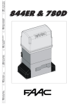
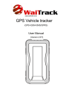
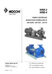
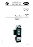
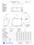
Installation Manual 740/741 Sliding Gate System Leading the way ... EC DECLARATION OF CONFORMITY FOR MACHINES (DIRECTIVE 98/37/EC) Manufacturer: FAAC S.p.A. Address: Via Benini, 1 - 40069 Zola Predosa BOLOGNA - ITALY Declares that: 740 / 741 mod. operator with electronic control unit 740D • is built to be integrated into a machine or to be assembled with other machinery to create a machine under the provisions of Directive 98/37/EC; • conforms to the essential safety requirements of the following EEC directives: 73/23/EEC and subsequent amendment 93/68/EEC. 89/336/EEC and subsequent amendment 92/31/EEC and 93/68/EEC and also declares that it is prohibited to put into service the machinery until the machine in which it will be integrated or of which it will become a component has been identified and declared as conforming to the conditions of Directive 98/37/EC. Bologna, 01 January 2004 The Managing Director A. Bassi WARNINGS FOR THE INSTALLER GENERAL SAFETY OBLIGATIONS 1) ATTENTION! To ensure the safety of people, it is important that you read all the following instructions. Incorrect installation or incorrect use of the product could cause serious harm to people. 2) Carefully read the instructions before beginning to install the product. 3) Do not leave packing materials (plastic, polystyrene, etc.) within reach of children as such materials are potential sources of danger. 4) Store these instructions for future reference. 5) This product was designed and built strictly for the use indicated in this documentation. Any other use, not expressly indicated here, could compromise the good condition/operation of the product and/or be a source of danger. 6) FAAC declines all liability caused by improper use or use other than that for which the automated system was intended. 7) Do not install the equipment in an explosive atmosphere: the presence of inflammable gas or fumes is a serious danger to safety. 14) Make sure that the earthing system is perfectly constructed, and connect metal parts of the means of the closure to it. 15) The automated system is supplied with an intrinsic anti-crushing safety device consisting of a torque control. Nevertheless, its tripping threshold must be checked as specified in the Standards indicated at point 10. 16) The safety devices (EN 12978 standard) protect any danger areas against mechanical movement Risks, such as crushing, dragging, and shearing. 17) Use of at least one indicator-light (e.g. FAACLIGHT ) is recommended for every system, as well as a warning sign adequately secured to the frame structure, in addition to the devices mentioned at point “16”. 18) FAAC declines all liability as concerns safety and efficient operation of the automated system, if system components not produced by FAAC are used. 19) For maintenance, strictly use original parts by FAAC. 8) The mechanical parts must conform to the provisions of Standards EN 12604 and EN 12605. For non-EU countries, to obtain an adequate level of safety, the Standards mentioned above must be observed, in addition to national legal regulations. 20) Do not in any way modify the components of the automated system. 9) FAAC is not responsible for failure to observe Good Technique in the construction of the closing elements to be motorised, or for any deformation that may occur during use. 22) Do not allow children or adults to stay near the product while it is operating. 10) The installation must conform to Standards EN 12453 and EN 12445. For non-EU countries, to obtain an adequate level of safety, the Standards mentioned above must be observed, in addition to national legal regulations. 11) Before attempting any job on the system, cut out electrical power . 21) The installer shall supply all information concerning manual operation of the system in case of an emergency, and shall hand over to the user the warnings handbook supplied with the product. 23) Keep remote controls or other pulse generators away from children, to prevent the automated system from being activated involuntarily. 24) Transit is permitted only when the automated system is idle. 25) The user must not attempt any kind of repair or direct action whatever and contact qualified personnel only. 12) The mains power supply of the automated system must be fitted with an all-pole switch with contact opening distance of 3mm or greater. Use of a 6A thermal breaker with all-pole circuit break is recommended. 26) Maintenance: check at least every 6 months the efficiency of the system, particularly the efficiency of the safety devices (including, where foreseen, the operator thrust force) and of the release devices. 13) Make sure that a differential switch with threshold of 0.03 A is fitted upstream of the system. 27) Anything not expressly specified in these instructions is not permitted. 1 AUTOMATED SYSTEM 740-741 These instructions apply to the following models: FAAC 740 - 741 The 740-741 gearmotor is an electro-mechanical operator designed for moving sliding gates. The non-reversing reduction system ensures the gate is mechanically locked when the gearmotor is not operating, therefore it is not necessary to install any electric lock A convenient manual release with customised key makes it possible to move the gate in the event of a power failure or malfunction of the operator. The 740-741 gearmotor was designed and built for controlling vehicle access. AVOID ANY OTHER USE WHATEVER. 1. DESCRIPTION AND TECHNICAL SPECIFICATIONS 1. Motor lid 2. Electronic control unit 3. Release device 4. Gearmotor body 5. Foundation plate 6. Pinion 7. Limit switch 8. Motor cover 9. Cable holes 10. Capacitor 11. Protective side panels 햲 햻 햳 햽 햵 햹 햸 햺 햷 햴 햶 MODEL Power supply (+6% -10%) Fig.01 740 741 740 115V 741 115V 230 V~ 50Hz 230 V~ 50Hz 115 V~ 60Hz 115 V~ 60Hz Absorbed power (W) 350 500 350 600 Absorbed current (A) 1.5 2.2 3 5.2 Capacitor (µF) 10 12.5 30 50 Thrust on pinion (daN) 45 65 45 65 18 24 18 24 Winding thermal protection (°C) Torque (Nm) 140 140 140 140 Leaf max weight (Kg) 500 900 500 900 Type of pinion Z16 Z16 Z16 Z16 Gate speed (m/min) 12 12 14 14 Gate max length (m) 15 15 15 15 Mechanical Mechanical Mechanical Mechanical Electronic Electronic Electronic Electronic Use frequency S3 - 30% S3 - 40% S3 - 30% S3 - 40% Operating temperature (°C) -20 +55 -20 +55 -20 +55 -20 +55 10 11 10 11 IP44 IP44 IP44 IP44 See Fig.02 See Fig.02 See Fig.02 See Fig.02 Type of limit switch Clutch Gearmotor weight (Kg) Protection class Gearmotor overall dimensions 2. DIMENSIONS 322 Values are expressed in mm 18 0 5 29 221 Fig.02 2 Warning:The Thearrow arrow foundation pate must always Warning: onon thethe foundation plate must always point to point to thesee gate, see Figs 05-06. the gate, Figs. 05-06. 3. MAXIMUM USE CURVE Percentuale di lav. % % Duty cycle % Fréquence d'utilisation % Benutzungsfrequenz 3- After determining the position of the foundation plate, make a plinth as shown in Fig. 07 and wall the plate, providing several sheaths for routing the cables. Using a spirit level, check if the plate is perfectly level. Wait for the cement to set. 4- Lay the electric cables for connection to the accessories and power supply as shown in diagram of Fig. 03. To facilitate connections to the control unit, allow the cables to protrude by at least 50 cm from the hole on the foundation plate. % Frecuencia de utilización 100 90 80 70 60 50 40 30 20 10 Values are expressed in mm 0÷50 Fig.05 90 ° Calculation use frequency frequency Calculation of use Use frequency is the percentage of effective work time (opening + closing) compared to total time of cycle (opening + closing + pause times). Calculation formula: Ta + Tc X 100 %F= Ta + Tc + Tp + Ti where: Ta = opening time Tc = closing time Tp = pause time Ti = time of interval between two complete cycles 90 ° 1 2 3 4 5 6 7 8 9 10 11 12 Tempo (h) Time (h) Temps (h) Zeit (Std.) Tiempo (h) 56±5 0 56±5 The curve makes it possible to establish maximum work time (T) according to use frequency (F). With reference to IEC 34-1 Standard, the 740-741 gearmotor with an S3 duty, can operate at a use frequency of 30-40%. To ensure efficient operation, it is necessary to operate in the work range below the curve. Important:the Thecurve curveisis obtained Important: obtained a temperature at aat temperature of 20oC.of 20°C. Exposure to the direct rays Exposure to the direct sunsun rays reduce use frequency cancan reduce frequency down to 20%down to 20%. Values are expressed in mm 0÷50 Fig.06 4. ELECTRICAL SET-UP (standard system) Values are expressed in mm 89 ,5 0 32 6 10 100 18 0 20 0 5 33 Fig.07 1- Operator with unit 2- Photocells 3- Key-operated push button 4- Flashing lamp 5- Radio receiver *other safety may be required 5.3. Mechanical installation Fig.03 5. INSTALLING THE AUTOMATED SYSTEM 5.1. Preliminary checks To ensure safety and efficiency of the automated system, make sure the following requirements are observed before installing the system: • The gate structure must be suitable for automation. The following are necessary in particular: wheel diameter must be in proportion to the weight of the gate, an upper track must be provided, plus mechanical travel stops to prevent the gate derailing. • The ground soil must guarantee a perfect stability of the foundation plinth. • There must be no pipes or electric cables in the plinth excavation area. • If the gearmotor is located in the vehicle transit or manoeuvre area, adequate means of protection should be provided against accidental impact. • Check if an efficient earthing is available for connection to the gearmotor. 1 Fig.08 Attention:This This operation is Attention: operation is necessary ensure rack necessary to to ensure thethe rack is is correctly secured and enable correctly secured and to to enable any new adjustments. any new adjustments. Values are expressed in mm 5.2. Masonry for foundation plate 4- Secure the gearmotor to the plate, tightening the nuts. 5- Prepare the operator for manual operation as described in paragraph 8. 60-80 1- Assemble the foundation plate as shown in figure 04. 2- In order to ensure that the pinion and rack engage correctly, the foundation plate must be positioned as shown in Fig. 05 (right closing) or Fig. 06 (left closing). 1- Remove the cover, Fig. 08 ref. 1. 2- Position the operator on the foundation plate, using the supplied washers and nuts as shown in Fig. 09. During this operation, route the cables through the appropriate openings in the motor body (See Fig.01 ref.9). If necessary, the two holes can be joined using a hammer to obtain a wider space. 3- Adjust the height of the gearmotor and the distance from the gate, referring to dimensions in Fig. 10. Fig.04 Fig.09 3 Values are expressed in mm 12,5 ÷ 50 42 90 (Z16) Values are expressed in mm Fig.15 56 6. START-UP Fig.10 5.4. Assembling the rack 5.4.1. Steel rack to weld (Fig. 11) 1) Fit the three threaded pawls on the rack element, positioning them at the bottom of the slot. In this way, the slot play will enable any future adjustments to be made. 2) Manually take the leaf into its closing position. 3) Lay the first section of rack level on the pinion and weld the threaded pawl on the gate as shown in Fig. 13. 4) Move the gate manually, checking if the rack is resting on the pinion, and weld the second and third pawl. Fig.11 5) Position another rack element end to end with the previous one, using a section of rack (as shown in Fig. 14) to synchronise the teeth of the two elements. 6) Move the gate manually and weld the three threaded pawls, thus proceeding until the gate is fully covered. 6.1. Control board connection Before attempting any work on the board (connections, programming, maintenance), always turn off power. Follow points 10, 11, 12, 13 and14 of the GENERAL SAFETY OBLIGATIONS. Following the instructions in Fig. 3, route the cables through the raceways and make the necessary electric connections to the selected accessories. Always separate power cables from control and safety cables (pushbutton, receiver, photocells, etc.). To avoid any electric noise whatever, use separate sheaths. 6.1.1. Earthing Connect the earth cables as shown in Fig.16 ref.A. 5.4.2. Steel rack to screw (Fig. 12) 1) Manually take the leaf into its closing position. 2) Lay the first section of rack level on the pinion and place the spacer between the rack and the gate, positioning it at the bottom of the slot. 3) Mark the drilling point on the gate. Drill a Ø 6,5 mm hole and thread with an M8 male tap. Screw the bolt. 4) Move the gate manually, checking if the rack is resting on the pinion, Fig.12 and repeat the operations at point 3. 5) Position another rack element end to end with the previous one, using a section of rack (as shown in figure 14) to synchronise the teeth of the two elements. 6) Move the gate manually and carry out the securing operations as for the first element, thus proceeding until the gate is fully covered. Notes on rack installation • Make sure that, during the gate travel, all the rack elements do not exit the pinion. • Do not, on any account, weld the rack elements either to the spacers or to each other. • When the rack has been installed, to ensure it meshes correctly with the pinion, it is advisable to lower the gearmotor position by about 1.5 mm (Fig.15). • Manually check if the gate correctly reaches the mechanical limit stops maintaining the pinion and rack coupled and make sure there is no friction during gate travel. • Do not use grease or other lubricants between rack and pinion. Fig.13 Fig.16 6.1.2. Electronic control unit In the gearmotors, the electronic control unit is fitted to an adjustable support (Fig. 16 ref. 1) with transparent lid (Fig. 16 ref. 3). The board programming push buttons (Fig. 16 ref. 4) have been located on the lid. This allow the board to be programmed without removing the lid. For correct connection of the control unit, follow indications the specific instructions: 6.2. Positioning the limit switches The operator has a mechanical travel stop with spring-lever, which commands gate movement to stop when a profiled steel plate, secured on the top of the rack, activates the spring until the microswitch is tripped. The plate support can be fitted to all racks with max. width of 13 mm. Procedure for correct positioning of the two Fig.17 travel stop plates supplied: 1) Fit and secure the 2 profiled steel plates on the 2 U-supports, using the supplied nuts and washers, as shown in figure 17. 2) Prepare the operator for manual operation as described in paragraph 8. 3) Power up the system. 4) Securing the opening limit switch: manually take the gate to opening position, leaving 20 mm from the mechanical travel stop. 5) Allow the plate to slide over the rack in opening direction (Fig.18). As soon as the opening limit switch LED on the control board goes off, take the plate forward by about 20÷30 mm and secure it provisionally on the rack, using the supplied screws. 6) Repeat the operations at points 4 and 5 for the closing limit switch, Fig. 19. Fig.14 4 1 2 3 2 3 Fig.19 Fig.18 Fig.26 Fig.25 8. MANUAL OPERATION Warning: toto thethe system to to prevent an an involuntary Warning:Cut Cutpower power system prevent involuntary pulse from activating thethe gate during the release manoeuvre. pulse from activating gate during the release manoeuvre. Fig.20 Important: To release the operator proceed as follows: 1) Insert the key provided and turn it clockwise as shown in Fig. 27 ref. 1 and 2. 2) Turn the release system clockwise, until the mechanical stop is reached, Fig. 27 ref. 3. 3) Open and close the gate manually. Important: a) The plate must activate the limit-switch on the profiled part as shown in figure 20. b) If the wheel and the travel stop plate are too close, it may be necessary to shorten the limit-switch spring by a couple of turns. Procedure for shortening the spring: anticlockwise This operation requires - To remove the spring, turn it clockwise. some force. - Shorten the spring as shown in Fig. 22: two turns correspond to about 3 mm. - Fit the spring turning it clockwise, Fig. 23, until the stop is reached; see Fig. 24. - Once the spring is back in place, ensure the wheel is horizontal. A wrong wheel orientation may jeopardise the operation of the limit switches. 3 2 1 Fig.27 9. RESTORING NORMAL OPERATION Warning: to the thesystem systemtoto prevent involuntary Warning: Cut power to prevent anan involuntary pulse pulse from activating gate during manoeuvre restorfrom activating thethe gate during thethe manoeuvre forfor restoring ingnormal normaloperation. operation. Fig.21 Values are expressed in mm Fig.22 To restore normal operation proceed as follows: 1) Turn the release system anti-clockwise, until its stop is reached, Fig. 28 ref. 1. 2) Turn the key anti-clockwise and remove it from the lock, Fig. 28 ref. 2 and 3. 3) Move the gate until the release system meshes (corresponds to gate locking) 4) Power up the system. 1 Fig.23 Fig.24 8) Re-lock the system (see paragraph 9). Important: sure thethe gate Important: Before Beforesending sendingaapulse, pulse,make make surethat that gate cannot be moved manually. cannot be moved manually. 9) Command a complete gate cycle to check if the limit switch is tripped correctly. Warning: the operator and/or interrupting Warning:To Toavoid avoiddamaging damaging the operator and/or interrupting operation of the system, allow a space of about operation of automated the automated system, allow a space of about 20 mm mechanical travel stops. 20mm fromfrom the the mechanical travel stops. 10) Appropriately adjust the position of the travel stop plates and definitively secure them on the rack. 2 3 Fig.28 10. SPECIAL APPLICATIONS There are no special applications. 11. MAINTENANCE 7. TESTING THE AUTOMATED SYSTEM After installing the operator, carefully check operating efficiency of all accessories and safety devices connected to it. Return the board support to its original position. Fit the cover (Fig. 25 ref. 1), tighten the two side screws provided (Fig. 25 ref 2) and snap-fit the side panels (Fig. 25 ref.3). Apply the danger sticker on the top of the cover (Fig. 26). Hand the “User’s Guide” to the Customer and explain correct operation and use of the gearmotor, indicating the potentially dangerous areas of the automated system. 5 Check the operational efficiency of the system at least once every 6 months, especially as regards the efficiency of the safety and release devices (including operator thrust force). 12. REPAIRS For any repairs, contact the authorised Repair Centres. 13. AVAILABLE ACCESSORIES Refer to the catalogue for available accessories. CONTROL BOARD 740D WARNINGS 3. LAYOUT AND COMPONENTS Important: Before attempting any work on the control board (connections, maintenance), always turn off power. F2 - Install, upstream of the system, a differential thermal breaker with adequate tripping threshold. DL - Connect the earth cable to the appropriate terminal on the J7 connector of the equipment (see fig. 30). + - Always separate power cables from control and safety cables (push-button, receiver, photocells, etc.). To avoid any electric noise, use separate sheaths or a shielded cable (with earthed shield). + – FCA OPEN B FSW OP STOP FCC OPEN A FSW CL EDGE SAFE F F TECHNICAL SPECIFICATIONS 2 3 4 5 7 J2 1 LIMITS 2 ENCODER 3 4 7 8 9 10 11 12 13 14 15 16 17 MOTOR J6 LAMP PE N L MAIN J7 9 10 11 12 PE N L LAMP N COM J1 CLOSE SIGNALLING AND PROGRAMMING DISPLAY INPUTS STATUS CONTROL LED LOW VOLTAGE TERMINAL BOARD CONNECTOR FOR DECODER/MINIDEC/RP RECEIVER ENCODER CONNECTOR LIMIT -SWITCH CONNECTOR MOTORS AND FLASHING LAMP CONNECTION TERMINAL BOARD POWER SUPPLY TERMINAL BOARD 115Vac(740D-115V)-230Vac(740D-230V) MOTORS AND TRANSF. PRIMARY FUSE (740D 115V=F10A - 740D 230V=F 5A) LOW VOLTAGE AND ACCESSORIES FUSE (T 800mA) "F" PROGRAMMING PUSH-BUTTON "–" PROGRAMMING PUSH-BUTTON "+" PROGRAMMING PUSH-BUTTON J7 J6 13 14 15 16 17 MOTOR ACCESSORIES LAMP PE N L MAIN C M 115Vac (740D 115V) max. 60W 230 Vac (740D 230V) max. 60W 115Vac 50-60Hz (740D 115V) 230Vac 50-60Hz (740D 230V) STOP STOP PARTIALLY OPEN TOTALLY TOTALLY OPEN PE N L N CLOSE COM OPEN W.L. + + TX-FSW 24V 6 J7 J6 ACCESSORIES OPEN DL Led J1 J2 J3 J5 J6 J7 F1 F2 F – + For connection of the photocells and safety devices, see paragraph 4.1. LIMIT-SWITCH LIMIT-SWITCH STOP 5 J1 J1 Fig. 29 24 Vdc 3W ENCODER (optional) F1 -- EDGE FSW CL OPEN B J3 J3 FSW OP J5J5 + + 8 Led ENCODER TX-FSW 24V EDGE 6 -- J2 BLUE BLUE 1 STOP ENCODER FSW CL LIMITS FSW OP J3 OPEN B J5 OPEN A ELECTRIC CONNECTIONS F1 RADIO OPEN A Model 740D-115V 740D-230V Power supply V~ ( +6% -10%) 50 Hz 115 230 Absorbed power (W) 10 10 Motor max. load (W) 1200 1000 Accessories max. load (A) 0.5 0,5 Operating ambient temperature -20 °C +55 °C Protection fuses 2 (see fig. 29) Function logics: Automatic / “Stepped” automatic / Semi-automatic / Safety devices / Semi-automatic B / Dead-man C / “Stepped” semi-automatic / Mixed B/C logic Work time Programmable (from 0 to 4 min.) Pause time Programmable (from 0 to 4 min.) Thrust force Adjustable over 50 levels Terminal board inputs Open / partial Pàartial opening / Safety devices at opng. / Safety devices at clsng. / Stop / Edge / Power supply + Earth On-connector inputs Opening and closing limit-switches / Encoder optional Terminal board outputs Flashing lamp - Motor - 24 Vdc accessories power supply - 24 Vdc indicator-light / Timed output. - Fail safe Rapid connector 5-pin card connection for Minidec, Decoder or RP receivers Programming 3 keys (+, -, F) and display, "basic" or "advanced" mode Basic mode programmable functions Function logic - Pause time - Thrust Force - Gate direction Advanced mode programmable functions: Torque at initial thrust - Braking - Fail safePre-flashing - Indicator-light/Timed output/Electric lock or 'traffic lights' command Opening and closing safety devices logic - Encoder/ Anti-crushing sensitivity Decelerations - Partial opening time - Work time - Assistance request - Cycle counter 4. - W.L. 2. F2 LAMP 1. Fig. 30 NB.: The capacitor is supplied with the operator. 6 Connection of photocells and safety devices 4 5 6 7 8 W.L. STOP EDGE 3 TX-FSW FSW CL 2 24V FSW OP 1 -- + + OPEN B Connection of an "edge" safety device OPEN A 4.1. Before connecting the photocells (or other devices) we advise you to select the type of operation according to the movement area they have to protect (see fig. 31): 9 10 11 12 Opening safety Opening/closing Opening/closing safety devices safety devices Opening safety devices devices Fig. 35 6 7 8 RX W.L. EDGE 5 TX-FSW STOP 4 + + FSW CL 3 24V FSW OP 2 9 10 11 12 TX 1 2 1 - 3 4 - 5 + + 2 Fig. 36 4 5 6 N.B. If two or more safety devices have the same function (opening, closing, opening and closing, edge), the contacts must be connected to each other in series (fig. 32). N.C. contacts must be used. 7 8 W.L. 3 TX-FSW 2 -- + + EDGE 1 24V STOP Connection of a pair of closing photocells FSW CL motion and stopping after two seconds. (Optional) 1 -- FSW OP Opening safety devices: they are tripped when an obstacle is deOpening safetygate devices: they are tripped when an obstacle is tected only during opening movement. They cause detected only during gate opening movement. They immediate closure and resumption of opening motion on release (see cause immediate closure and resumption of opening programming in par 5.2). motion on release (see programming in par.5.2). Closing safety devices: they are tripped when an obstacle is Closing safety devices: they are trippedThey when an obstacle is detected only during gate closing movement. cause re-opening, detected only during gate closing movement. They caueither immediate or on release se re-opening, either immediate or on release (see (see programming in par 5.2). programming in par.5.2). Opening/closing safety devices: they are tripped during the gate Opening/closing safety devices: are trippedand during the opening and closing movements. Theythey cause stopping restart opening and closing movements. They cause motion on gate release. stopping and restart motion release. “Edge” safety devices: they are trippedonduring the gate opening and "Edge" safety devices: are tripped during theofgate opening closing movements, They they cause immediate reversal motion and andtwo closing movements. They cause immediate reversal stopping after seconds. stopping after twoduring seconds. Encoder: of it ismotion trippedand if there is an obstacle gate opening and Encoder: it is tripped if thereimmediate is an obstacle during gate opening closing movements. It causes reversal of motion and stopand closing movements. It causes immediate reversal of ping after two seconds. (optional) OPEN B Fig. 31 device OPEN B closingClosing safety device safety OPEN A “Edge” safety devices "Edge" safety devices OPEN A Connection of a pair of photocells for opening 9 10 11 12 RX TX 1 2 Connection of two N.C. contacts in series (e.g. Photocells, Stop, Edge, etc.) Fig. 32 RX CL Fig. 33 6 7 8 W.L. 5 TX-FSW 4 -- + + 3 24V 2 EDGE STOP 1 9 10 11 12 FSW CL 8 FSW OP 7 + OPEN B 6 - 5 Connection of a pair of opening photocells, a pair of closing photocell and an edge safety device OPEN A STOP EDGE 5 W.L. FSW CL 4 TX-FSW FSW OP 3 24V OPEN B 2 + + OPEN A Connection of no safety device 1 4 + 2 Fig. 37 N.B: If safety devices are not used, jumper connect the terminals as shown in fig. 33. -- 1 - 3 9 10 11 12 TX CL 1 2 The most common photocell and safety device lay-outs are shown below (from fig. 34 to fig. 41). - 5 + TX OP W.L. TX-FSW 24V -- + + STOP EDGE FSW CL FSW OP OPEN B OPEN A Connection of a closing safety device and an opening safety device - 1 3 4 + 2 RX OP 1 2 1 2 3 4 5 6 7 8 9 10 11 12 1 2 + 3 - 4 + 5 Fig. 38 Fig. 34 7 1 9 10 11 12 6 RX CL 7 8 W.L. 5 TX-FSW 4 24V 3 -- + + 2 EDGE STOP 8 FSW CL 7 FSW OP 6 OPEN A STOP EDGE 5 W.L. FSW CL 4 TX-FSW FSW OP 3 24V OPEN B 2 + + OPEN A 1 -- OPEN B Connection of a pair of closing photocells and a pair of opening/closing photocells Connection of two pairs of closing photocells and two edge safety devices 9 10 11 12 TX CL 1 2 - 1 3 TX CL1 RX CL1 1 2 4 - 5 + + 2 - 1 3 + 2 4 - 5 + 1 2 1 2 RX CL2 TX CL2 1 5 2 1 3 4 TX OP/CL RX OP/CL Fig. 41 3 2 4 5 Fig. 39 Connection of two N.O. contacts in parallel (e.g. Open A, Open B) STOP EDGE 4 5 6 7 8 W.L. FSW CL 3 TX-FSW FSW OP 2 -- + + OPEN B 1 24V OPEN A Connection of a pair of closing photocells, a pair of opening photocells and a pair of opening/closing photocells Fig. 42 9 10 11 12 4.2. J7 Terminal board - Power supply (fig. 30) RX CL POWER SUPPLY (terminals PE-N-L): PE : Earth connection N : Power supply ( Neutral ) L : Power supply ( Line ) TX CL 1 2 - 1 3 4 - 5 + NB.: For correct operation, the board must be connected to the earth conductor in the system. Install an adequate differential thermal breaker upstream of the system. + 2 4.3. J6 Terminal board - Motors and flashing lamp (fig. 30) MOTOR - (terminals 13-14-15): Motor connection. In gearmotors with a built-in control unit, this connection is prewired standard. For leaf opening direction, see basic programming in par. 5.1. LAMP - (terminals 16 -17): Flashing lamp output. 1 2 1 3 2 4 5 TX OP/CL RX OP 4.4. J1 Terminal board - Accessories (fig. 30) RX OP/CL OPEN A - "Total Opening" command (terminal 1): any pulse generator (push-button, detector, etc.) which, by closing a contact, commands total opening and/or closing of the gate leaf. To install several total opening pulse generators, connect the N.O. contacts in parallel (see fig. 42). TX OP 1 2 - 1 3 4 - 5 + + 2 Fig. 40 OPEN B - "Partial opening " or "Closing" command (terminal 2): any pulse generator (push-button, detector, etc.) which, by closing a contact, commands partial opening and/or closing of the gate leaf. In the B, C and B/C logics, it always commands gate closure. To install several partial opening pulse generators, connect the N.O. contacts in parallel (see fig. 42). 8 FSW OP - Opening safety devices contact (terminal 3): The purpose of the opening safety devices is to protect the leaf movement area during opening. During opening, in the AAP-S-E-EP logics the safety devices reverse the movement of the gate leaves, or stop and restart the movement when they are released (see advanced programming in Par 5.2). During the opening cycle in logics B, C and B/C, they interrupt movement. They never operate during the closing cycle. If the Opening safety devices are engaged when the gate is closed, they prevent the leaf opening movement. To install several safety devices, connect the N.C. contacts in series (fig. 32). NB.: If no opening safety devices are connected, jumper connect inputs OP and -TX FSW (fig. 33). FSW CL - Closing safety devices contact (terminal 4): The purpose of the closing safety devices is to protect the leaf movement area during closing. During closing, in the AAP-S-E-EP logics, the safety devices reverse the movement of the gate leaves, or stop and reverse the movement when they are released (see advanced programming in Par 5.2). During the closing cycle in logics B, C and B/C, they interrupt movement. They never operate during the opening cycle. If the Closing safety devices are engaged when the gate is open, they prevent the leaf closing movement. To install several safety devices, connect the N.C. contacts in series (fig. 32). NB.: If no closing safety devices are connected, jumper connect terminals CL and -TX FSW (fig. 33). STOP - STOP contact (terminal 5): any device (e.g. a pushbutton) which, by opening a contact, is able to stop gate movement. To install several STOP devices, connect the N.C. contacts in series. NB.: If STOP devices are not connected, jumper connect the STOP and - terminals. EDGE - EDGE safety device contact (terminal 6): The purpose of the "edge" safety device is to protect the leaf movement area during opening/closing against fixed obstacles (pillars, walls, etc.). In all logics, during opening and closing, the safety devices reverse gate leaf movement for 2 seconds. If the safety devices operate again during the 2-seconds reversing time, they STOP movement without any reversing. If the Edge safety devices are engaged while the gate is closed or open, they prevent the leaves movement. To install several safety devices, connect the N.C. contacts in series (fig. 32). NB.: If edge safety devices are not connected, jumper connect the EDGE and - inputs. (fig. 33). – Negative for power supply to accessories (terminals 7 and 8) + 24 Vdc - Positive for power supply to accessories (terminals 9 and 10) Important: Accessories max. load is 500 mA. To calculate absorption values, refer to the instructions for individual accessories. TX -FSW - Negative for power supply to photocell transmitters (terminal 11) If you use this terminal for connecting the negative for supplying power to the photocell transmitters, you may, if necessary, also use the FAIL SAFE function (see advanced programming in par. 5.2). If this function is enabled, the equipment checks operation of the photocells before every opening or closing cycle. W.L. - Power supply to indicator light / timed exit / electric lock/ 'traffic lights' (terminal 12) Connect any 24 Vdc - 3 W max indicator light, timed exit, command device for electric lock or 'traffic lights' between this terminal and the +24V (see advanced programming in par. 5.2). To avoid geopardising correct operation of the system, do not exceed the indicated power. 9 4.5. Connector J2 - Rapid connection to Minidec, Decoder and RP This is used for rapid connection of Minidec, Decoder and RP receivers (see fig. 43, 44, 45). Connect the accessory, with the components side facing the inside of the board. Insert and remove after cutting power. PLUS PLUS 740D 740D 740D 740D DECODER MINIDEC Fig. 44 Fig. 43 RP 740D 740D Fig. 45 4.6. Connector J6 - Limit-switches rapid connection (fig. 30) This input is intended for rapid connection of the opening and closing limit-switches designed to stop the leaf, or for start of decelerations or for braking (see advanced programming in Par. 5.2.). In gearmotors with a built-in control unit, this connection is pre-wired as standard (fig. 30). For leaf opening direction, see advanced programming in Par 5.2. 4.7. Connector J3 - Encoder rapid connection (fig. 30) This input is designed for rapid connection of the Encoder (optional). To fit the encoder on the motor, refer to the relevant instructions. The presence of the encoder is signalled - when the gearmotor is running - by the flashing of the "Encoder" LED on the board. When the encoder is used, the control unit knows the exact position of the gate while it is moving. The encoder controls the adjustments of some of the control unit's functions in a different way (partial opening or deceleration - see advanced programming in Par 5.2) and as an anti-crushing device. If the gate strikes an obstacle during opening or closing, the encoder immediately reverses the gate leaf for 2 seconds. If the encoder operates again during the 2 seconds reversing time, it STOPS movement without commanding any reversing. 5. PROGRAMMING To program operation of the automated system, you have to access the "PROGRAMMING" mode. Programming is split into two parts: BASIC and ADVANCED. 5.1. BASIC PROGRAMMING To access BASIC PROGRAMMING, press key F: •if you press it (and hold it down), the display shows the name of the first function. •if you release the key, the display shows the value of the function that can be modified with keys + and -. •if you press F again (and hold it down), the display shows the name of the next function, etc. •when you reach the last function, press F to exit the program, and the display resumes showing the gate status. The following table shows the sequence of functions accessible in BASIC PROGRAMMING: BASIC PROGRAMMING Display 5.2. ADVANCED PROGRAMMING To access ADVANCED PROGRAMMING, press key F and, as you hold it down, press key +: •if you release key + , the display indicates the name of the first function. •if you release key F too, the display shows the value of the function that can be modified with keys + and -. •if you press key F (and hold it down), the display shows the name of the next function, and if you release it, the value that can be modified with keys + and - is shown. •when you reach the last function, press F to exit the program, and the display resumes showing the gate status. The following table shows the sequence of functions accessible in ADVANCED PROGRAMMING: F Function Default FUNCTION LOGICS (see table of logics): PA PAUSE TIME: This has effect only if the automatic logic was selected. Adjustable from 0 to 5 0 sec. in one-second steps. Subsequently, display changes to minutes and tens of seconds (separated by a point) and time is adjusted in 10-second steps, up to the maximum value of 4.1 minutes. E.g. if the display shows is 2 min. and 50 sec. FO d1 EP ADVANCED PROGRAMMING Display bo OPENING DIRECTION: Indicates the gate opening movement and makes it possible not to change the motor and limitswitches connections on the terminal board. = Right-hand opening movement E - = Left-hand opening movement br 50 STATUS OF AUTOMATED SYSTEM: Exit from programming, save data, and return to gate status viewing. 0 0 = Closed 0 1 = Now opening 0 2 = At "STOP" 0 3 = Open 0 4 = Pause 0 5 = "FAIL SAFE" tripped 0 6 = Now closing 0 7 = Now reversing 0 8 = Photocells tripped Function MAXIMUM TORQUE AT INITIAL THRUST: FINAL BRAKING: When the gate engages the opening or closing limit-switch, a braking stroke can be selected to ensure the leaf is stopped immediately. If decelerations are selected, braking starts when they finish. At 0 0 value, braking is disabled. Time can be adjusted from 0 1 to 2 0 in 0.01-second steps. 00 from FS E- SE + + Default y y = Active n o = Disabled 2.5, pause time FORCE: Adjusts Motor thrust. 0 1 = minimum force 5 0 = maximum force F The motor operate at maximum torque (ignoring the torque setting) at start of movement. Useful for heavy leaves. 2.0 E- LO A = Automatic A P = "Stepped" automatic S = "Safety" Automatic E = Semi-automatic E P = "Stepped" Semi-automatic C = Dead-man b = "B" Semi-automatic b C = Mixed Log. (B opening / C closing) 05 = Braking disabled to 2 0 = Timed braking 01 FAIL SAFE: If this function is activated, it enables a function test of the photocells before any gate movement. If the test fails (photocells on not serviceable signalled by value the display), the gate does not start moving. no y = Active n o = Disabled PRE-FLASHING (5 s): PF Activates the flashing lamp for 5 seconds before start of movement. no oP CC OC 10 = Disabled = Only before opening = Only before closing = Before every movement no Display Function Default Display INDICATOR-LIGHT: SP If 0 0 is selected, the output functions as a standard indicator-light (lighted at opening and pause, flashing at closing, and off when gate closed). Courtesy light: Different figures correspond to timed activation of the output, which can be used (by a relay) to power a courtesy lamp. Time can be adjusted from 1 to 5 9 sec. in 1-second steps, and from 1.0 to 4.1 min. in 10-second steps. Electric lock command and 'traffic lights' functions: If you press key - from the 0 0 setting, the command for theE 1closing electric lock is activated; If you press - again, the command for the E 2 closing and opening electric lock is set; if you press the - key again, you can set the 'traffic lights' functions E 3 and E 4 . 0 0 = Standard indicator-light from 0 1 to 4.1 = Timed output. E 1 = electric lock command before opening movement E 2 = electric lock command before opening and closing movements E 3 = 'traffic lights' function: the output is active in "open" and "open on pause" status and is disabled 3 seconds before the closing manoeuvre starts. Note: there is 3 seconds of pre-flashing before the closing manoeuvre. E 4 = 'traffic lights' function: the output is active only in "closed" status. Attention: do not exceed the output's maximum load (24Vdc-3W). If necessary, use a relay and a power supply source outside the equipment. 00 EC Ph Select the tripping mode of the closing photocells. They operate for the closing movement only: they stop movement and reverse it when they are released, or they reverse it immediately. rP Pre-limit switch DECELERATION: You can select gate deceleration before the opening and closing limit-switches have been tripped. Time can be adjusted from 0 0 to 9 9 in 0.04-second steps. If an encoder is used, the adjustment is not determined by time but by motor revs, thus obtaining greater deceleration precision. 00 = Deceleration disabled from 0 1 to 9 9 = Deceleration enabled no Post-limit switch DECELERATION: You can select gate deceleration after the opening and closing limit-switches have been tripped. 05 Time can be adjusted from 0 0 to 2 0 in 0.02-second steps. If an encoder is used, the adjustment is not determined by time but by motor revs, thus obtaining greater deceleration precision. 0 0 = Deceleration disabled from 0 1 to 2 0 = Deceleration enabled OPENING PHOTOCELLS LOGIC: Select the tripping mode of the opening photocells. They operate for the opening movement only: they stop the movement and restart it when they are released, or they reverse it immediately. 00 00 y = Reverse on release n o = Reverse immediately to opening oP Default from 0 1 to 9 9 = Encoder active and sensitivity adjustment 0 0 = Encoder disabled rA CLOSING PHOTOCELLS LOGIC: Function ENCODER: If the encoder is used, you may select its presence. If the encoder is present and enabled, "decelerations" and "partial opening" are controlled by the encoder (see relevant paragraphs). The encoder operates as an anti-crushing device: If the gate strikes an obstacle during opening or closing, the encoder immediately reverses gate leaf movement for 2 seconds. If the encoder operates again during the 2-seconds reversing time, it stops movement (STOP) without commanding any reversing. If no sensor is supplied, the parameter must be set on 0 0 . If there is the encoder, adjust the sensitivity of the anti-crushing system, by varying the parameter between 0 1 (maximum sensitivity) and 9 9 (minimum sensitivity). no PARTIAL OPENING: PO y = Reverse immediately to closing n o = Restart movement on release 11 You can adjust the width of partial leaf opening. Time can be adjusted from 0 1 to 2 0 in 1-second steps. If an encoder is used, the adjustment is not determined by time but by motor revs, thus obtaining greater partial-opening precision. For example, with pinion Z20, partial opening can vary from about 60 cm to 4 m. 05 Display E Function Default WORK TIME (time-out): We advise you to set a value of 5 to 10 seconds over the time taken by the gate to travel from the closing limit-switch to the opening limit-switch and vice versa. Adjustable from 0 to 5 9 sec. in onesecond steps. Subsequently, display changes to minutes and tens of seconds (separated by a point) and time is adjusted in 10 second steps, up to a maximum value of 4.1 minutes. 4.1 AS If activated, at the end of countdown (settable with the next function i.e. "Cycle programming") it effects 2 sec. (in addition to the value already set with the PF function) of pre-flashing at every Open pulse (job request). Can be useful for setting scheduled maintenance jobs. LEDS FCA FCC OPEN B OPEN A FSW OP FSW CL STOP EDGE no SE OFF Limit-switch engaged Limit-switch engaged Command inactive Command inactive Safety devices engaged Safety devices engaged Command activated Safety devices engaged NB.: 7. FINAL OPERATIONS CYCLE PROGRAMMING: For setting countdown of system operation cycles. Settable (in thousands) from 0 0 to 9 9 thousand cycles. The displayed value is updated as cycles proceed. This function can be used to check use of the board or to exploit the "Assistance request". LIGHTED Limit-switch free Limit-switch free Command activated Command activated Safety devices disengaged Safety devices disengaged Command inactive Safety devices disengaged • The status of the LEDs while the gate is closed at rest are shown in bold. y = Active n o = Disabled nc 6.1. INPUTS CHECK The table below shows the status of the LEDs in relation to to the status of the inputs. Note the following: LED LIGHTED = closed contact LED OFF = open contact Check the status of the LEDs as per Table. Operation of the signalling status LEDs Attention: the set value does not exactly matchthe motor's maximum operating time, because the latter is modified according to the performed deceleration spaces. ASSISTANCE REQUEST (combined with next function): 6. START-UP 00 At end of programming, run a few complete cycles to check if the automated system and the accessories connected to it are operating correctly, giving special attention to safety devices, operator thrust force adjustment, and to the anti-crushing device (Encoder sensor, optional). Hand over the "User's guide" page (in the operator instructions) to the customer, and describe how the system works, as well as the operator release and locking operations indicated in the said guide. GATE STATUS: Exit from programming, data saving, and return to viewing gate status (see par. 5.1.). NB.: modification of programming parameters comes into effect immediately, whereas definitive memory storage occurs only when you exit programming and return to gate status viewing. If the equipment is powered down before return to status viewing, all modifications will be lost. To restore the default settings of the programming disconnect terminal strip J1, press the three buttons +, -, F simultaneously and keep them pressed for 5 seconds. 12 13 No effect (1) (3) Closes the leaf (3) OPENING LOCKED Closes the leaf (3) LOCKED Re-closes the leaf immediately (3) Re-opens the leaf immediately Stops operation (3) Closes the leaf (with Closing Safety devices engaged, opens at the 2nd pulse) (3) CLOSING OPENING LOCKED Opens the leaf CLOSED Opens leaf for the partial opening time OPEN OPEN-A Logic "E" GATE STATUS OPEN-B Re-closes the leaf immediately (3) OPENING Tab. 3/d Re-opens the leaf immediately CLOSING CLOSED Re-closes the leaf immediately (3) Opens leaf for the partial opening time and closes after pause time Opens the leaf and closes it after pause time OPEN on PAUSE OPEN-B OPEN-A GATE STATUS Logic "S" Tab. 3/c LOCKED Stops operation (3) OPENING Closes the leaf (with Closing Safety devices engaged, opens at the 2nd pulse) (3) Re-opens the leaf immediately CLOSING CLOSED Stops operation (3) Opens leaf for the partial opening time and closes after pause time Opens the leaf and closes it after pause time OPEN on PAUSE OPEN-B OPEN-A GATE STATUS Logic "AP" Tab. 3/b Re-opens the leaf immediately (1) CLOSING Opens the leaf and closes it after pause time (1) CLOSED Reloads pause time (1)(3) Opens leaf for the partial opening time and closes after pause time (1) OPEN on PAUSE OPEN-B OPEN-A GATE STATUS Logic "A" Tab. 3/a No effect (OPEN disabled) Stops operation STOP No effect (OPEN disabled) Stops operation STOP No effect (OPEN disabled) Stops operation STOP No effect (OPEN disabled) Stops operation STOP PULSES No effect CLOSING SAFETY DEVICES see paragraph 5.2. No effect (saves OPEN) No effect No effect (if on part.opng. OPEN A disabled) No effect (OPEN disabled) OPENING SAFETY DEVICES Reverses to close for 2" (2) Reverses to close for 2" (2) Locks and, on release, continues opening EDGE SAFETY DEVICE Locks and, on release, continues opening No effect (saves OPEN) No effect No effect see paragraph 5.2. No effect (3) (OPEN disabled) EDGE SAFETY DEVICE Reverses to close for 2" (2) Locks and, on release, continues opening No effect (OPEN disabled) Reverses to open for 2" (2) Locks and, on release, reverses to open No effect (OPEN disabled) No effect (OPEN disabled) OP/CL SAFETY DEVICE No effect OPEN disabled) Reverses to close for 2" (2) Reverses to open for 2" (2) Locks and, on release, reverses to open see paragraph 5.2. No effect (OPEN disabled) OP/CL SAFETY DEVICE No effect (OPEN disabled) Reverses to open for 2" (2) Locks and, on release, reverses to open Reloads pause time (OPEN disabled) Reloads pause time (OPEN disabled) EDGE SAFETY DEVICE No effect (OPEN disabled) OP/CL SAFETY DEVICE No effect (OPEN disabled) Reverses to open for 2" (2) Reloads pause time (1) (OPEN disabled) Locks and, on release, continues opening Reloads pause time (1) (OPEN disabled) Locks and, on release, reverses to open Reloads pause time (1) (OPEN disabled) CLOSING SAFETY DEVICES No effect PULSES see paragraph 5.2. No effect (saves OPEN) EDGE SAFETY DEVICE No effect (OPEN disabled) OP/CL SAFETY DEVICE On release, closes after 5" (OPEN disabled) No effect On release, closes after 5" (OPEN (if on part.opng. OPEN A disabled) disabled) (3) No effect (OPEN disabled) OPENING SAFETY DEVICES No effect see paragraph 5.2. Reloads pause time (3) (OPEN disabled) No effect CLOSING SAFETY DEVICES No effect PULSES see paragraph 5.2. No effect (saves OPEN) No effect (if on part.opng. OPEN A disabled) No effect (OPEN disabled) OPENING SAFETY DEVICES PULSES No effect No effect see paragraph 5.2. see paragraph 5.2. Reloads pause time (1) (3) No effect (saves OPEN) No effect CLOSING SAFETY DEVICES No effect (if on part.opng. OPEN A disabled) No effect (OPEN disabled) OPENING SAFETY DEVICES 14 LOCKED / Stops operation No effect (OPEN-B disabled) Stops operation / OPEN CLOSING OPENING No effect Reverses to open No effect Opens the leaf OPEN CLOSING OPENING LOCKED No effect Opens the leaf No effect Reverses to open No effect Opens the leaf CLOSED OPEN CLOSING OPENING LOCKED No effect (OPEN A/B disabled) Stops operation No effect (OPEN B disabled) STOP No effect (OPEN A/B disabled) Stops operation No effect (OPEN B disabled) STOP Stops operation No effect (OPEN-A/B disabled) STOP (1) If maintained, it prolongs the pause until disabled by the command (timer function) (2) If a new pulse occurs within 2 seconds after reversing, it immediately stops operation. Closes the leaf No effect No effect Closes the leaf OPEN-B (closing) OPEN-A (opening) GATE STATUS Logic "B/C" Closes the leaf No effect No effect Closes the leaf No effect OPENING PULSE/CLOSING HOLD TO RUN CONTROLS Opens the leaf CLOSED Tab. 3/h OPEN-A (opening) Logic "B" GATE STATUS OPEN-B (closing) Closes the leaf Opens the leaf CLOSED Tab. 3/g No effect (OPEN-A disabled) OPEN-B (closing) OPEN-A (opening) Logic "C" GATE STATUS CONTROLS ALWAYS HELD DOWN No effect (if it must open, it disables OPEN) Tab. 3/f see paragraph 5.2. No effect (OPEN disabled) Stops operation (3) Restarts movement in reverse direction (3) (always closes after a Stop) OPENING PULSES No effect Stops operation (OPEN-A disabled) EDGE SAFETY DEVICE Reverses to close for 2" (2) Locks and, on release, continues opening EDGE SAFETY DEVICE EDGE SAFETY DEVICE Reverses to close for 2" (2) Reverses to open for 2" (2) No effect (OPEN-A/B disabled) Reverses to close for 2" (2) Reverses to open for 2" (2) No effect (OPEN-A/B disabled) EDGE SAFETY DEVICE Reverses to close for 2" (2) Reverses to open for 2" (2) No effect (OPEN-A/B disabled) No effect (OPEN A/B disabled) Stops operation (OPEN-A/B disabled) No effect (OPEN B disabled) No effect (OPEN A disabled) OP/CL SAFETY DEVICE No effect (OPEN A/B disabled) Stops operation (OPEN-A/B disabled) No effect (OPEN B disabled) No effect (OPEN A disabled) OP/CL SAFETY DEVICE Stops operation (OPEN-A/B disabled) No effect (OPEN B disabled) No effect (OPEN A disabled) OP/CL SAFETY DEVICE No effect (OPEN disabled) Reverses to open for 2" (2) Locks and, on release, reverses to open No effect (OPEN disabled) No effect (OPEN disabled) OP/CL SAFETY DEVICE (3) During the partial opening cycle, an OPEN A pulse causes total opening. NB.: Effects on other active pulse inputs in brackets. No effect (OPEN B disabled) Stops operation (OPEN-B disabled) No effect (saves OPEN A) No effect (OPEN-A disabled) No effect (OPEN B disabled) No effect CLOSING SAFETY DEVICES No effect No effect (OPEN A disabled) OPENING SAFETY DEVICES No effect (OPEN B disabled) No effect No effect (saves OPEN A) Stops operation (OPEN-A disabled) No effect (OPEN-A disabled) Stops operation (OPEN-B disabled) No effect No effect No effect (OPEN B disabled) No effect (OPEN A disabled) OPENING SAFETY DEVICES CLOSING SAFETY DEVICES No effect Stops operation (OPEN-A disabled) PULSES Stops operation (OPEN-B disabled) No effect (OPEN B disabled) No effect CLOSING SAFETY DEVICES PULSES No effect (if it must close, it disables OPEN) No effect see paragraph 5.2. No effect (OPEN disabled) (3) No effect CLOSING SAFETY DEVICES No effect No effect (OPEN A disabled) No effect (OPEN A disabled) OPENING SAFETY DEVICES No effect (saves OPEN) Stops operation Stops operation No effect (if on part.opng. OPEN A disabled) No effect (OPEN disabled) CLOSING CLOSED PULSES OPENING SAFETY DEVICES Re-closes the leaf immediately (3) Opens leaf for the partial opening time Opens the leaf STOP OPEN OPEN-B OPEN-A GATE STATUS Logic "EP" Tab. 3/e Users guide 1 3 2 2 1 3 Fig.01 Fig.02 AUTOMATED SYSTEM 740-741 Read the instructions carefully before using the product and keep them for future consultation. GENERAL SAFETY RULES If installed and used correctly, the 740-741 automated system will ensure a high degree of safety. Some simple rules regarding behaviour will avoid any accidental trouble: • Do not stand near the automated system and do not allow children and other people or things to stand there, especially while it is operating. • Keep radiocontrols or any other pulse generator well away from children to prevent the automated system from being activated involuntarily. • Do not allow children to play with the automated system. • Do not willingly obstruct gate movement. • Prevent any branches or shrubs from interfering with gate movement. • Keep light signalling systems efficient and clearly visible. • Do not attempt to activate the gate by hand unless you have released it. • In the event of malfunctions, release the gate to allow access and wait for qualified technical personnel to do the necessary work. • After enabling manual operation, switch off the power supply to the system before restoring normal operation. • Do not make any alterations to the components of the automated system. • Do not attempt any kind of repair of direct action whatsoever and contact qualified personnel only. • Call in qualified personnel at least every 6 months to check the efficiency of the automated system, safety devices and earth connection. DESCRIPTION The 740-741 automated system is ideal for controlling vehicle access areas of medium transit frequency. The 740-741 automated system for sliding gates is an electromechanical operator transmitting motion to the sliding gate via a rack pinion or chain appropriately coupled to the gate. Operation of the sliding gate is controlled by an electronic control unit housed inside the operator or in a hermetically sealed outdoor enclosure. When, with the gate closed, the unit receives an opening command by radiocontrol or from another suitable device, it activates the motor until the opening position is reached. If automatic operation was set, the gate re-closes automatically after the selected pause time has elapsed. If the semi-automatic operation was set, a second pulse must be sent to close the gate again. An opening pulse during re-closing, always causes movement to be reversed. A stop pulse (if provided) always stops movement. The light signalling indicates that the gate is currently moving. For details on sliding gate behaviour in different function logics, consult the installation technician. The automated systems include obstacle-detection and/or safety devices (photocells, edges) that prevent the gate from closing when 15 there is an obstacle in the area they protect. The system ensures mechanical locking when the motor is not operating and, therefore, it is not necessary to install any lock. Manual opening is, therefore, only possible by using the release system. The gearmotor does not have a mechanical clutch and, therefore, it is coupled to a unit with an electronic clutch offering the necessary anti-crushing safety if the system is completed with the necessary safety devices. A convenient manual release with customised key makes it possible to move the gate in the event of a power failure or malfunction. MANUAL OPERATION Warning:Cut Cutpower power to to the system to prevent prevent an Warning: aninvoluntary involuntarypulse pulse from activating thethe gate during the the release manoeuvre. from activating gate during release manoeuvre To release the operator proceed as follows: 1) Insert the key provided and turn it clockwise as shown in Fig. 01 ref. 1 and 2. 2) Turn the release system clockwise, until the mechanical stop is reached, Fig. 01 ref. 3. 3) Open and close the gate manually. RESTORING NORMAL OPERATION Warning: Cut power to the system to prevent an involuntary pulse from activating the gate during the manoeuvre for restoring normal operation. To restore normal operation proceed as follows: 1) Turn the release system anti-clockwise, until its stop is reached, Fig. 02 ref. 1. 2) Turn the key anti-clockwise and remove it from the lock, Fig. 02 ref. 2 and 3. 3) Move the gate until the release system meshes (corresponds to gate locking). 4) Power up the system. MAINTENANCE To ensure trouble-free operation and a constant safety level, an overall check of the system should be carried out every 6 months. A form for recording routine maintenance operations is enclosed. REPAIRS For any repairs, contact the authorised Repair Centres. AVAILABLE ACCESSORIES Refer to catalogue for available accessories. 16 The descriptions and illustrations contained in this manual are not binding. FAAC reserve the right, whilst leaving the main features of the main equipment unaltered, to undertake any modifications it holds necessary for either technical or commercial reasons, at any time and without revising the present publication. FAAC (UK) Limited, 6 Hamilton Close Houndmills Estate, Basingstoke, RG21 6YT Telephone: 01256 318100 Fax: 01256 318101 Email: [email protected] Website: www.faac.co.uk V5 01/07 Your authorised FAAC dealer