1
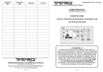
IMPORTANT
Keep this service manual to hand during the machine/
equipment's working life
“AMENITY”
SPRAYERS
user manual
ENGLISH
Edition 1
09-2003
IDM CO3680372.fm
Serial number
All rights reserved. No part of this service manual may be reproduced without written authorisation from the manufacturer. Our company has an on-going policy of improvement and this manual may be updated without prior notice being issued as long as there is no
safety risk involved. © 2003 - IDM esperti in comunicazione tecnica - Forlì - Author of the text, illustrations and page layout. This text is registered as IDM's intellectual property and may be partially or entirely reproduced with acknowledgements to the author.
- DIVISIONE SPRAYERS
SPRAYERS DEPT.
via della Cooperazione, 20 - 40026 IMOLA (BO) - ITALY
tel.+390542648511 - fax +390542640539 www.bargam.com - e-mail: [email protected]
- DIVISIONE MACCHINE AGRICOLE DA RACCOLTA
HARVESTING AGRICULTURAL MACHINERY DEPT.
- DIVISIONE DECANTER ECOLOGICI E INDUSTRIALI
ECOLOGICAL AND INDUSTRIAL DECANTER DEPT.
- DIVISIONE IMPIANTI OLEARI
OIL'S PLANT DEPT.
via Rossini, 148 - frazione STRADA - 62011 CINGOLI (MC) - ITALY
tel. +390733616726 - fax +390733616554 www.bargam.com - e-mail: [email protected]
Index
368.037
1
GENERAL INFORMATION
1.1.
PURPOSE OF THE MANUAL.........................3
1.2.
MANUFACTURER’S IDENTIFICATION
AND EQUIPMENT ..........................................4
1.3.
LIST OF ANNEXES ENCLOSED....................4
2
TECHNICAL INFORMATION
2.1.
OPERATION DIAGRAMS ...............................6
2.3.
TECHNICAL SPECIFICATIONS .....................9
2.4.
SAFETY DEVICES........................................10
2.5.
SAFETY RATING PLATES POSITION AND DESCRIPTION ...................11
2.6.
ATTACHMENTS UPON REQUEST..............13
3
SAFETY INFORMATION
3.1.
GENERAL SAFETY REGULATIONS ...........14
3.2.
HANDLING SAFETY REGULATIONS ..........14
3.3.
OPERATION SAFETY REGULATIONS .......14
3.4.
ADJUSTMENT AND MAINTENANCE
SAFETY REGULATIONS..............................15
4
HANDLING AND LOADING
4.1.
TRANSPORTATION AND PACKAGING ......16
4.2.
LOADING AND UNLOADING .......................16
4.3.
CLAMPS OF THE REMOVABLE
UNIT - INSTALLATION ................................17
5.1.
HITCHING TO TRACTOR............................ 26
Front tracker trailed units - hitching to tractor......26
Mounted units - hitching to tractor ................ 28
Trailed units - hitching to tractor ................... 29
Removable units - hitching to tractor ............ 31
Cardan shaft coupling (just for TRAILED
UNITS, FRONT TRACKER TRAILED
UNITS and MOUNTED UNITS).................... 32
6.1.6 Hydraulic connection (if fitted) ...................... 34
6.2.
6.4. DESCRIPTION OF CONTROLS .................. 38
6.4.1 Description of the distributor
(STANDARD 461) ........................................ 39
6.4.2 Description of the distributor (IDROMINUS).......40
6.4.3 Description of the distributor
(ELECTRO 461) ........................................... 42
DRAWBAR LENGTH - ADJUSTMENT
(JUST FOR TRAILED UNITS) ......................21
TRACK - ADJUSTMENT...............................22
5.3.
WATER DISTRIBUTOR - POSITION
ADJUSTMENT (ONLY FOR
TRAILED AND REMOVABLE UNITS) ..........22
PRECAUTIONS TO BE ADOPTED
DURING THE TRANSFER WITH
HITCHED EQUIPMENT ............................... 34
6.3. UNCOUPLING FROM THE TRACTOR ....... 34
6.3.1 Front tracker trailed units uncoupling from tractor................................. 35
6.3.2 Mounted units - uncoupling from the tractor .......36
6.3.3 Trailed units - uncoupling from tractor .......... 36
6.3.4 Removable units - uncoupling from the tractor...37
ADJUSTMENT AND SETTING UP
5.2.
USE AND OPERATION
6.1.
6.1.1
6.1.2
6.1.3
6.1.4
6.1.5
GENERAL DESCRIPTION
OF THE SPRAYERS.......................................5
2.2.
5
6
6.5.
TANK FILLING ............................................. 45
6.6.
CHEMICAL PRODUCTS HANDLING .......... 46
6.7.
CHEMICAL PRODUCT MIXTURE PREPARATION........................... 46
6.8.
CHEMICAL PRODUCT SPRAYING............. 50
6.9.
EMPTYING THE TANK FROM
THE RESIDUES ........................................... 51
7
EQUIPMENT MAINTENANCE
7.1.
DAILY MAINTENANCE ................................ 52
7.2.
SUCTION FILTER CLEANING..................... 54
7.3.
ROUTINE MAINTENANCE EVERY 40 HOURS ...................................... 55
7.4. UNSCHEDULED MAINTENANCE ............... 55
7.4.1 Equipment functions control devices. ........... 56
PRODUCT SPRAYING PARAMETERS SETTING UP .......................23
5.4.1 Tractor forward speed calculation .................24
5.4.2 Nozzles spray check .....................................24
7.5.
WINTER STOP............................................. 56
8
TROUBLESHOOTING
8.1.
TROUBLES, CAUSES, CURES................... 57
5.4.
–2–
1GENERAL INFORMATION
1
368.037
1.1.
PURPOSE OF THE MANUAL
Read carefully this manual before servicing
the equipment.
This manual defines the purpose for which the equipment has been designed and manufactured and contains all the information necessary to ensure a safe
and correct operation.
This manual has been drafted by the Manufacturer and it
is integral part of the equipment.
Tractor operating instructions, as well as safety information, are included here.
Some important parts of the text have been highlighted
and preceded by the symbols shown and defined below.
Said information is aimed at the professional user (operator), who, in addition to a specific skill relevant to the driving
of the tractor on which this equipment is fitted, must also
have acquired a certain experience in the field for which
this equipment has been designed and manufactured.
DANGER-WARNING: it shows an impending
danger which might cause serious injury; give it
the greatest attention.
CAUTION: it points out situations requiring a
particular procedure to avoid accidents or damages to property.
Furthermore, a generic mechanical experience and an agricultural mechanics skill are of the utmost importance to
allow the user either to fit the equipment or to carry out adjustment and maintenance operations in safe conditions.
INFORMATION: Important technical information.
DANGER-WARNING: it is absolutely forbidden to
any user and / or operator to use the equipment for a
different aim than the ones it is specifically conceived
for.
In pursuing a policy of constant development and updating of the product, the manufacturer might introduce changes to the equipment without any prior
notice.
–3–
GENERAL INFORMATION
368.037
Front tracker trailed units
Mounted units
Trailed units
Removable units
1.2.
A
B
C
D
E
F
G
-
1.3.
MANUFACTURER’S IDENTIFICATION AND
EQUIPMENT
A
Manufacturer’s identification.
Model.
Serial number.
Dry weight.
Total permitted weight.
Max. pressure.
Year of construction.
1
H
B
E
C
D
F
G
LIST OF ANNEXES ENCLOSED
Booklets including information about different elements that can be assembled to Your tractor are enclosed.
Even if your tractor is considerably different from pictures shown in this document, safety information is valid in any case.
–4–
Annexes enclosed:
❑ Spraying boom operation manual .......booklet F.
2TECHNICAL INFORMATION
2
368.037
2.1.
GENERAL DESCRIPTION OF THE SPRAYERS
“AMENITY” is a complete line of sprayers, consisting
of equipment engineered and manufactured by assembling several elements in order to meet different
operational needs.
Setting up of the units
The main units forming “AMENITY” equipment are
shown in the picture:
A - Spray product tank.
B - Pump
C - Water distributor.
D - Fresh water container.
E - Clothes holder (upon request)
F - Mixer
G - Blob marking tank (if fitted).
H - Hose reel (if fitted)
L - Spraying boom (see booklet F)
The sprayers consist of equipment with diversified
characteristics, devised for agricultural use and, in particular, for spraying chemical substances (fertilisers,
weed-killers, antiparasitic substances, etc.) on the
ground or directly on cultivated products.
This equipment, coupled to the tractor, contains chemical substances to be sprayed. A pump driven by the
tractor power take off, through a cardan shaft, directs
the product to the spraying boom.
Front tracker trailed units
Mounted units
D
A
E
C
D
C
E
A
B
F
L
B
Trailed units
Removable units
A
C
A
H
B
L
G
L
C
H
F
F
G
B
D
E
IDM - 37.002 Ec.0
–5–
D
E
TECHNICAL INFORMATION
368.037
2.2.
OPERATION DIAGRAMS
We describe herewith the different types of operation
cycles according to the models of sprayers and the
types of control units.
De-mountable sprayers with electric control unit
IDM-3680370621.tif
–6–
2
TECHNICAL INFORMATION
368.037
Trailed sprayers with manual control unit
Special mixing with
bottom return pipe
(on demand)
IDM-3680370601.tif
De-mountable sprayers with manual control unit
Special mixing
with bottom return
pipe (on demand)
IDM-3680370611.tif
–7–
2
TECHNICAL INFORMATION
368.037
0RXQWHGVSUD\HUVZLWKPDQXDOFRQWUROXQLW
Special mixing
with bottom return
pipe (on demand)
IDM-3680370581.tif
Trailed sprayers with manual control unit
Special mixing with
bottom return pipe
(on demand)
IDM-3680370591.tif
–8–
2
TECHNICAL INFORMATION
368.037
2.3.
2
TECHNICAL SPECIFICATIONS
Front tracker trailed units
Mounted units
Model
Capacity I
A mm B mm C mm
kg
SAG 200 Amenity
200
1550 1400 1250
140
Model
Capacity I
POG 200 Amenity
POG 300 Amenity
POG 400 Amenity
POG 600 Amenity
POG 800 Amenity
200
300
400
600
800
A mm B mm C mm
1540
1540
1540
2050
2455
710
710
710
810
955
1200
1350
1550
1600
1856
kg
89
93
105
161
208
Removable units without feet
Trailed units
Model
Capacity l
A mm B mm C mm kg
GTG 650 Amenity
GTG 850 Amenity
600
800
1350 2630 1315 300
1350 2630 1280 321
Model
Capacity l
GSG 350 Amenity
GSG 450 Amenity
GSG 600 Amenity
GSG 650 Amenity
GSG 850 Amenity
300
400
600
600
800
Removable units with feet
Model
Capacity l
GSG 350 Amenity
GSG 450 Amenity
GSG 600 Amenity
GSG 650 Amenity
GSG 850 Amenity
300
400
600
600
800
A mm B mm C mm
2080
2080
2080
2180
2180
1650
1650
1650
1910
1910
1215
1350
1530
1350
1495
kg
186
190
210
226
235
–9–
A mm B mm C mm
1620
1620
1620
1720
1720
1600
1600
1600
1860
1860
1085
1220
1400
1220
1365
kg
186
190
210
226
235
TECHNICAL INFORMATION
368.037
Q Technical residue
The volume of the liquid which can not be correctly
distributed does not exceed 0.5% of the nominal volume plus 2 litres per boom meter.
Model
nominal cap. (l)
GSG350 Amenity
GSG450 Amenity
Residual volume (l)
soluble
not soluble
total
300
10
3,4
13,4
400
10
3,4
13,4
GSG600 Amenity
600
10
3,4
13,4
GSG650 Amenity
600
11,4
3,5
14,9
GSG850 Amenity
800
11,4
3,5
14,9
Note: data in the table refer to equipment with 6m booms.
2.4.
SAFETY DEVICES
A - Fixed guard; cardan transmission protection.
Mounted units
Front tracker trailed units
A
Trailed units
A
Removable units
A
A
IDM - 37.003 Ec.0
– 10 –
2
TECHNICAL INFORMATION
368.037
2.5.
2
SAFETY RATING PLATES - POSITION AND DESCRIPTION
INFORMATION: Make sure all the rating plates
are clear, otherwise replace them and position
them exactly in the same point.
4
4
1
1
A - Danger of arms crushing. Give the
greatest attention during the hooking to
the tractor height adjustment.
C - Read this manual. The operator using
the equipment must read this manual to
know the position and controls function
and learn all the information contained
herein. The manual must always be kept
within reach.
5
D - Always wear gloves. To be used whenever handling products.
6
E - Wear a gas-mask. To be worn whenever handling and using chemical products.
5
2
2
B - Genericdanger. Turn off the tractor and
read the operation manual before carrying out any servicing whatsoever.
Front tracker trailed units
L
M
M
6
Mounted units
C-D-E
F-G-H
M
L
A-B-N-P
C-D-EF-G-H
A-B-N-P
M
C-D-E-F-G
T
T
Trailed units
Removable units
C-D-E
F-G-H
B
C-D-E
F-G-H
A-B-N-P
C-D-E
F-G
M
A-B-N-P
T
L
C-D-E
F-G
M
M
T
M L
– 11 –
TECHNICAL INFORMATION
368.037
7
F - Wear protective clothes. To be worn
whenever handling and using chemical
products.
7
8
8
8
G- Arms corrosion danger. Give the
greatest attention whenever handling
chemical products. Always wear gloves.
H - General danger. Warning: do not introduce any parts of your body into the tank.
8
10
L - Always use clean water. Always wash
hands when handling chemical products.
10
15
15
M - Do not pass. Non-authorised
people are not allowed to stand
or pass within the machine
range.
N - Warning: general danger. Do not
use pressure exceeding 20 bars.
P - Warning: danger of pressurised oil
leaks. Read the instruction manual
before carrying out any maintenance
operations on the machine.
T - general danger. Before fitting
in the cardan shaft, check the
direction of rotation and
number of revolutions of the
power takeoff.
– 12 –
2
TECHNICAL INFORMATION
368.037
2.6.
2
ATTACHMENTS UPON REQUEST
The attachments that can be installed on “AMENITY”
equipment are listed and described below.
The attachments that can be installed on different
models of equipment are listed in the table.
Front tracker
trailed units
Mounted units
Trailed units
Removable
units
Mixer kit
•
•
• ( *)
System washing kit
•
•
•
Foam marker kit
•
•
•
Hose reel kit
•
•
•
Special mixing kit
•
•
•
•
•
•
Attachment
Electric distributor
•
(*) Current accessories for units with 650 and 850-litre tanks.
Q Mixer kit
It mixes chemical substances with water inside the
tank.
Q System washing kit
To wash the fluid distribution ducts at the end of the
working cycle.
Q Foam marker kit
It consists of an air compressor, a blob marking tank
and two sprayers fitted on the spraying boom end.
Whenever this device is operating, foam blobs fall on
the ground, thus marking the ground already sprayed.
Q Hose reel kit
It allows to reel the hose used for the attachment “nozzle”.
Q Special mixing kit
Enables to keep the liquid agitated in the tank during
spraying in order to avoid any product settling.
Q Electric distributor
It is equipped with electric motors for valve opening
and closing; it is also equipped with a control board
that can be positioned in the tractor driver’s cabin.
– 13 –
3SAFETY INFORMATION
3
368.037
3.1.
GENERAL SAFETY REGULATIONS
Read carefully this operation and maintenance instruction manual before carrying out
any installation, starting, operation, adjustment or maintenance, etc.
• Said equipment requires the use and handling of
chemical substances, thus making the knowledge of
these products necessary to avoid damages to people and environment. All the instructions supplied by
the Manufacturer of said substances must be duly
complied with.
• As far as the user’s safety is concerned, always wear
the personal safety clothes and devices to prevent
the products from being breathed and avoid any contact with the body.
3.2.
• Danger, do not dispose of the residues in the environment:
• fluids and/or chemicals residues must be disposed of
in accordance with the law in force.
• The Manufacturer declines any liability whatsoever
for damages to people, animals or property should
the safety regulations fail to be complied with.
• The operator shall not use the tractor when taking
drugs, alcohol or narcotics, which might cause side
effects, thus reducing his concentration.
• Read carefully the rating plates fixed on the equipment or other parts and make sure to observe the relevant instructions.
HANDLING SAFETY REGULATIONS
• Lifting and handling operations must be carried out
• Do not stand under suspended loads.
through suitable means and by skilled personnel.
3.3.
OPERATION SAFETY REGULATIONS
• Do not use controls or hoses as a grip.
• Do not leave the tractor and the equipment unattended, unless all safety devices the manufacturer supplied at this purpose have been activated.
• Do not allow people (particularly children and handicapped people) to approach the tractor especially
during its running.
• Do not operate it if guards and protections have been
removed or desactivated.
• Do not work if the safety devices have not been activated or fail to work properly.
• Do not use the equipment as a means of transport or
towing.
• As far as road circulation is concerned, the equipment must be supplied with the safety devices in
compliance with the Motor Vehicle Regulation in
force in the user’s country.
• The user and/or operator shall not use the equipment
– 14 –
for purposes differing from those determined by the
manufacturer.
• Do not use the tractor and the equipment on gradients greater than those determined by the manufacturer.
• Make sure to mark all tools used to prepare the
chemical products and do not use them for other purposes.
• Always wear overalls, gloves, boots, helmet, a mask
protecting from dust, and goggles.
SAFETY INFORMATION
368.037
3.4.
ADJUSTMENT AND MAINTENANCE SAFETY REGULATIONS
• Non-authorised personnel shall not be allowed to
carry out repairs or maintenance or any other servicing operation.
• Unscheduled maintenance and repairs must be carried out in well equipped workshops.
• Any change introduced either on the tractor or equipment must be previously authorised in writing by the
manufacturer.
• Remove dangling clothes which might entangle into
the running parts.
• Before carrying out any cleaning, maintenance or repair, the operator must make sure to activate the
safety devices, turn off the tractor engine, remove
the ignition key, taking it with him.
• Do not enter for any reason whatsoever into the tank.
• Should it be necessary to replace parts, always ask
for original spare parts
– 15 –
3
4HANDLING AND LOADING
4
368.037
4.1.
TRANSPORTATION AND PACKAGING
The equipment can be shipped by road, train or ship.
Whatever the solution, the equipment is always unpacked.
4.2.
LOADING AND UNLOADING
· Use a lifting hook of a suitable capacity or a fork lift
DANGER-WARNING: Lifting and handling operations must be carried out through suitable
means and by skilled personnel.
device as shown in figure.
· Slowly lift and handle the equipment avoiding oscillations.
Front tracker trailed units
Mounted units
Trailed units
Removable units
IDM - 37.005 Ec.0
– 16 –
HANDLING AND LOADING
368.037
4.3.
CLAMPS OF THE REMOVABLE UNIT - INSTALLATION
Gambettibarre supplies clamps together with the removable unit, in order to install them on the specific
means of transport.
Further on you will find the assembly diagrams of the
clamps related to the following means of transport:
– TORO LONG
– TORO SCHORT
– CUSHMAN
– JACOBSEN
TORO pin
Use TORO screws
TORO pin
Use TORO screws
IDM - 37.006 Ec.0
– 17 –
4
HANDLING AND LOADING
368.037
4
è Clamp installation for Toro LongClamp installation for Toro SCHORT
TORO pin
TORO pin
Use TORO screws
Use TORO screws
IDM - 37.007 Ec.0
è Clamp installation for CUSHMAN
CUSHMAN pin
CUSHMAN screws
IDM - 37.008 Ec.0
– 18 –
HANDLING AND LOADING
368.037
è Clamp installation for JACOBSEN
JACOBSEN screws
JACOBSEN screws
IDM - 37.009 Ec.0
è Clamp installation for JD ProGator Short
Use JD ProGator screws
IDM-3680370680.tif
– 19 –
4
HANDLING AND LOADING
368.037
è Clamp installation for JD ProGator Long
IDM-3680370690.tif
– 20 –
4
5ADJUSTMENT AND SETTING UP
5
368.037
5.1.
DRAWBAR LENGTH - ADJUSTMENT (just for TRAILED UNITS)
è Length adjustment
The drawbar can be adjusted at three lengths, proceeding as shown below.
A
CAUTION: this operation has to be carried out
on flat ground, after locking trailed tank frame
and wheels, as shown in the figure.
C
B
· Unscrew and take screws A out.
· Loosen screws B.
· Move drawbar C in the position you want, aligning
the holes.
· Fit screws A, and tighten them with their respective
nuts.
· Tighten screws and lock nuts B.
IDM - 37.010 Ec.0
C
è Height Adjustment
· Loosen screws A, B and C.
· Put the drawbar at the height you want.
· Tighten screws A and B.
· Screw tight screw C and tighten its respective lock
nut.
450,6 325
IDM - 37.011 Ec.0
157,6
C
A
B
– 21 –
ADJUSTMENT AND SETTING UP
368.037
5.2.
TRACK - ADJUSTMENT
DANGER-WARNING: This operation must be
carried out on flat ground after the equipment
has been hitched to the tractor, the parking brake
engaged and the tank emptied.
· Slightly lift the axle using a suitable lifting device.
· Loose bolts A and adjust the track into the position
required, without exceeding the max. extension
measure (270 mm).
A
· Tighten bolts A.
· Carry out the same operation on the opposite wheel.
CAUTION: After the first kilometre has been
covered with the equipment hitched, make sure
bolts (A) and lock nuts have been properly tightened.
Legend:
(1) Minimum and maximum tracks for 650-litre units.
(2) Minimum and maximum tracks for 850-litre units.
5.3.
IDM - 37.012 Ec.0
1100(1) / 1200(2)
1450(1) / 1550(2)
WATER DISTRIBUTOR - POSITION ADJUSTMENT (only for TRAILED and REMOVABLE UNITS)
· Loosen knobs A, B (C only in removable units) and
adjust the distributor position.
· Once the distributor position has been adjusted,
tighten the knobs.
IDM - 37.013 Ec.0
B
A
C
– 22 –
5
ADJUSTMENT AND SETTING UP
368.037
5.4.
5
PRODUCT SPRAYING - PARAMETERS SETTING UP
Parameters must be set in accordance with the tractor
forward speed, (to be chosen according to the ground
conditions), the quantity of litres per hectare of product
to be sprayed (always follow the instructions printed on
the product label) and in accordance with the kind of
nozzle to be used.
The working pressure can be obtained through the following parameters of the distribution table fitted on the
tank.
The only purpose of said table is to provide the user
with a consulting example as far as the search of the
values is concerned.
❑ Distribution table
ISO
Yellow
11002
Blue
11003
Red
11004
bar
l/min
1,5
2
3
4
5
1,5
2
3
4
5
1,5
2
3
4
5
0,56
0,66
0,8
0,91
1,02
0,85
0,98
1,2
1,39
1,55
1,13
1,31
1,6
1,85
2,07
4 km/
h
168
198
240
273
306
255
294
360
417
465
339
393
480
555
621
5 km/
h
134
158
192
218
245
204
235
288
334
372
271
314
384
444
497
6 km/
h
112
132
160
182
204
170
196
240
278
310
226
262
320
370
414
7 km/
h
96
113
137
156
175
146
168
206
238
268
194
225
274
317
355
Values search example
Quantity to be sprayed shown
on the product label................. 151 l per hectare (l/ha)
Forward speed ..................................................9 km/h
Nozzle ...................................... 11004 red type nozzle
By searching these values (see the highlighted area in
the table), the correct pressure will be thus obtained. In
this case, it is of 1.5 bar.
CAUTION: Working pressure must range between 1.5 and 5 bar.
Should the pressure value obtained from the table differ from the above mentioned pressure value, change
the forward speed value or the type of nozzle.
To make sure the adjustment has been performed
properly, carry out a test by spraying clean water.
– 23 –
8 km/
h
84
99
120
137
153
128
147
180
209
233
170
197
240
278
311
9 km/
h
75
88
107
121
136
113
131
160
185
207
151
175
213
247
276
10
12
14
16
18
20
km/h km/h km/h km/h km/h km/h
67
56
48
42
37
34
79
66
57
50
44
40
69
60
53
48
96
80
68
61
55
109 91
78
77
68
61
122 102 87
102 85
73
64
57
51
118 98
84
74
65
59
120 120 103 90
80
72
139 139 119 104 93
83
155 155 133 116 103 93
136 113 97
85
75
68
157 131 112 98
87
79
192 160 137 120 107 96
222 185 159 139 123 111
248 207 177 155 138 124
ADJUSTMENT AND SETTING UP
368.037
5
5.4.1 Tractor forward speed calculation
Should the tractor fail to be supplied with an odometer,
the forward speed must be calculated as follows:
· set the correct forward speed, according to the tractor engine rpm, by covering a known distance;
· cover a hundred metres run previously plotted, keep-
ing the engine number of revolutions steady and
measuring the time it took in seconds
· see the speed control table to obtain the forward
speed according to the time it took.
❑ Speed control table
SPEED (km/h)
TIME x 100 m (sec)
4
90
5
72
6
60
0m
7
51
8
45
10
36
12
30
100 m
IDM - 37.014 Ec.0
5.4.2 Nozzles spray check
Once the product spray parameters have been set,
make sure the quantity value relevant to the sprayed
product is the same as the value shown in the table.
è Check of each nozzle spraying (l/min)
· Position a measuring container under a nozzle working with clean water, at a pressure previously set, for
exactly one minute.
· Make sure the quantity of water thus collected is the
same as the value shown in the table.
· Carry out this operation on three or four nozzles.
– 24 –
è Check of the spraying of litres per hectare (l/ha)
· This check must be carried out through a spraying
test with clean water on an area of ground hundred
meters long, following the procedure below:
· set the forward speed and working pressure values
as described in § 5.4.;
re-fill the tank;
· spray water with the boom unfolded on a hundred
meters distance;
· re-fill the tank, measuring the litres of water which
have already been sprayed;
· check on the table relevant to the spraying test carried out on a hundred meters, that the value relevant
to product quantity to be sprayed (ex.: 200 l/ha) and
the boom length (ex. 10 m) corresponds to the litres
of water already sprayed.
ADJUSTMENT AND SETTING UP
368.037
5
è Table relevant to the spraying test carried out on a hundred meters
boom length (m)
Quantity of product
to be sprayed in l/ha
6
8
10
12
12,5
14
15
16
18
20
21
24
100
150
200
300
400
500
600
6
9
12
18
24
30
36
8
12
16
24
32
40
48
10
15
20
30
40
50
60
12
18
24
36
48
60
72
12,5
18,7
25
37,5
50
62,5
75
14
21
28
42
56
70
84
15
22,5
30
45
60
75
90
16
24
32
48
64
80
96
18
27
36
54
72
90
108
20
30
40
60
80
100
120
21
31,5
42
63
84
105
126
24
36
48
72
96
120
144
litresx100 m
To obtain more precise data, carry out the above mentioned test on a five hundred meters run; in such a
case, the value of the litres of water sprayed shall be
five times higher than the value shown on the table.
0m
100 m
IDM - 37.014 Ec.0
è Formula for the checking of the fluid litres sprayed per hectare (l/ha)
Quantity sprayed (l/ha)=
Fluid per nozzle (l/min) x constant 600
Distance among jets (0.5 m) x speed km/h
Said formula can be changed to obtain the necessary
forward speed or to determine the quantity of fluid to be
sprayed by each nozzle.
Speed km/h =
Fluid per nozzle (l/min) x constant 600
Quantity sprayed (l/ha) x distance among jets
Sprayed quantity (l/ha) x distance among jets x speed km/h
Fluid per nozzle l/min = Constant 600
– 25 –
6USE AND OPERATION
6
368.037
DANGER-WARNING: the equipment has to be
coupled to the tractor by only one operator, in absolute safety conditions.
IDM - 37.015 Ec.0
6.1.
HITCHING TO TRACTOR
Before hitching the equipment to the tractor, make always sure that the tractor has a suitable power as well
as proper size, in order to avoid towing and working
problems.
Hitching depends on the equipment you have:
– Front tracker trailed units - hitching to tractor (see
paragraph 6.1.1)
– Mounted units - hitching to tractor (see paragraph
6.1.2)
– Trailed units - hitching to tractor (see paragraph
6.1.3)
– Removable units - hitching to tractor (see paragraph
6.1.1 Front tracker trailed units - hitching to tractor
· Tractor hitch has to be positioned just next to the
hitch A.
A
– 26 –
USE AND OPERATION
368.037
6
· Hitch the equipment.
· Lift support legs B.
IDM - 37.017 Ec.0
B
· Couple the boom feed pipes to the water distributor.
IDM - 37.054 Ec.0
· Couple the cardan shaft to the tractor.
INFORMATION: some information about checking whether the cardan shaft length is fair, is included in chapter 6.1.5
– 27 –
IDM - 37.018 Ec.0
USE AND OPERATION
368.037
6.1.2 Mounted units - hitching to tractor
· Position the lower arms of the tractor height adjustment in line with pins A.
· Move the tractor backward until arm holes F are
aligned with pins A.
· Turn off the engine, engage the parking brake and
get out of the tractor removing and taking the ignition
key.
· Hook the two arms to the pins.
· Adjust the third point B length and fasten it to the
equipment through the relevant pin in the correct position, so that during the working phase, the equipment is perpendicular to the ground.
CAUTION: always fit the locking pins E, in order to prevent arms from coming out from pins.
Do not use unsuitable pins.
E
B
E
F
IDM - 37.019 Ec.0
· Couple the cardan shaft to the tractor.
INFORMATION: chapter 6.1.5 includes the instructions to check whether the cardan shaft
length is right.
IDM - 37.032 Ec.0
– 28 –
E
A
6
USE AND OPERATION
368.037
6.1.3 Trailed units - hitching to tractor
· Adjust support leg A, until trailed tank frame is parallel to the ground.
A
H
H
IDM - 37.020 Ec.0
· If necessary, adjust drawbar height (see paragraph
5.1.) or modify (if possible) towing hitch height, in order to put both hitches at the same height.
· Move the tractor backward until the towing hitch eye
and towing hitch C are aligned.
· Turn off the engine, engage the parking brake, get
out of the tractor removing the ignition key and taking
it away.
· Hitch the equipment to the tractor by inserting the pin
D and the related lock pin E.
– 29 –
D
E
C
6
USE AND OPERATION
368.037
· Fold support A to its stowage position.
A
IDM - 37.022 Ec.0
· Couple the cardan shaft to the tractor.
INFORMATION: chapter 6.1.5 includes the instructions to check whether the cardan shaft
length is right.
IDM - 37.023 Ec.0
– 30 –
6
USE AND OPERATION
368.037
6.1.4 Removable units - hitching to tractor
· Move the tractor below the equipment, so that hitch
points are at the same height.
CAUTION: stop the vehicle, engage the parking
brake and take the ignition key with you.
IDM - 37.024 Ec.0
· Rest the equipment on the tractor, lowering the support legs.
IDM - 37.025 Ec.0
· Fasten the equipment to the tractor with the screws
and the clamp supplied (see paragraph 4.3.).
IDM - 37.026 Ec.0
– 31 –
6
USE AND OPERATION
368.037
6
· Reclose the support legs.
· Couple the cardan shaft to the tractor.
INFORMATION: chapter 6.1.5 includes the instructions to check whether the cardan shaft
length is right.
IDM - 37.027 Ec.0
6.1.5 Cardan shaft coupling (just for TRAILED UNITS, FRONT TRACKER TRAILED UNITS and MOUNTED
UNITS)
DANGER-WARNING: This operation must be
carried out with the tractor turned off and previously disengaging the PTO.
Trailed units
The cardan shaft must have a suitable length in order
to avoid any jamming in conditions of minimum extension or an excessive risk of removal in conditions of
maximum extension.
To set the correct cardan shaft length, follow the procedure below.
· Position the sprayer at a minimum distance between
the tractor PTO and the pump spline shaft as shown
in the figure
IDM - 37.028 Ec.0
Mounted units
IDM - 37.029 Ec.0
– 32 –
USE AND OPERATION
368.037
· Remove the inner tube from the guard of the cardan
shaft and fix one half to the pump and the other half
to the tractor.
· Bring the two halves close together and make sure
that once the cardan shaft has been completely
closed, the stroke is at least of 15 mm.
· Cut either the exceeding parts of the tube or of guard
C, whenever necessary.
C
C
A
min 15 mm
IDM - 37.030 Ec.0
INFORMATION: During the operation, the telescopic tubes must be overlapped by at least 1/3 of
their length.
· Before the two parts are joined together again, re-
min 1/3 L
move the metallic burs, clean and lubricate the inner
tube.
· To avoid damage, make sure the space required by
the cardan shaft during the tractor operation is free.
· During the operation, standard cardan shafts must
not exceed a misalignment of 35° max.
· In case of misalignment exceeding 35°, use wide angle cardan shafts.
L
IDM - 04.026 Ec.0
For any additional information relevant to the cardan
shaft, such as operation and maintenance, see the
specific manual enclosed herein.
– 33 –
6
USE AND OPERATION
368.037
6
6.1.6 Hydraulic connection (if fitted)
Said operation is to be carried out exclusively on
equipment supplied with hydraulic controls.
– pressure pipe (P), fitted on the quick hitch and recognisable by the red protection cap;
– return pipe (T) fitted on the quick hitch and recognisable by the blue protection cap and by the check
valve fitted on the electrohydraulic systems only.
Connect the hydraulic "pressure" pipe to the tractor
pressure intake and the "return" pipe to the tractor return intake.
IDM - 37.031 Ec.0
T P
CAUTION: Whenever the identification of the
hydraulic intakes (pressure-return) on the tractor is not made possible, previously check their
function through the positioning of the relevant
changeover lever fitted on the tractor.
6.2.
PRECAUTIONS TO BE ADOPTED DURING THE TRANSFER WITH HITCHED EQUIPMENT
Before moving with the equipment hitched to the tractor, it is always necessary to carry out the following operations:
· make sure the equipment has been properly hitched,
see paragraph § 6.1.;
· make sure the tractor PTO has been disengaged;
6.3.
· make sure the spraying boom has been folded and
the relevant locking devices to prevent its unfolding
have been correctly fitted (see annex F);
· make sure that no chemical substance is inside the
spray product tank. In this case, see chapter 6.9.
UNCOUPLING FROM THE TRACTOR
Uncoupling procedures depend on the equipment you
have:
– Front tracker trailed units - uncoupling from tractor
(see paragraph 6.3.1)
– Mounted units - uncoupling from tractor (see paragraph 6.3.2)
– 34 –
– Trailed units - uncoupling from tractor (see paragraph 6.3.3)
– Removable units - uncoupling from tractor (see paragraph 6.3.4)
USE AND OPERATION
368.037
6.3.1 Front tracker trailed units - uncoupling from tractor
· Turn the tractor off, engage the parking brake and
take the ignition key with you.
· Lower support legs B.
IDM - 37.033 Ec.0
B
· Uncouple the cardan shaft C.
· Uncouple the boom feed pipes from the water distributor.
· Uncouple the tractor from the equipment and reverse
it.
DANGER-WARNING: There could be some
product spills, therefore it is necessary to use protective gloves.
C
IDM-3680370651.tif
– 35 –
6
USE AND OPERATION
368.037
6.3.2 Mounted units - uncoupling from the tractor
· Stand the equipment on the ground.
· Stop the tractor, engage the parking brake and take
the ignition key with you.
· Uncouple the three-point linkage.
· Uncouple the cardan shaft and place it on support B.
B
IDM - 37.034 Ec.0
6.3.3 Trailed units - uncoupling from tractor
· Stop the tractor, engage the parking brake and take
the ignition key with you.
· Rotate support leg A and lower it by means of the
handle.
A
IDM - 37.035 Ec.0
· Uncouple the cardan shaft and place it on support B.
B
IDM - 37.036 Ec.0
– 36 –
6
USE AND OPERATION
368.037
· Unplug both pin E and coupling pin D.
E
D
IDM - 37.021 Ec.0
6.3.4 Removable units - uncoupling from the tractor
· Stop the tractor, engage the parking brake and take
the ignition key with you.
· Loosen the securing screws from the tractor frame.
· Place support legs A in the right position.
A
IDM - 37.037 Ec.0
· Uncouple the clamps from the tractor frame.
· Lift the equipment by means of handles B.
· Uncouple both the cardan shaft and the water system pipes (if fitted).
B
IDM - 37.025 Ec.0
– 37 –
6
USE AND OPERATION
368.037
6.4.
DESCRIPTION OF CONTROLS
Front tracker trailed
units
Mounted units
A
A
Trailed units
A
B
A
The diagram shows the position and function of the
controls on the equipment. More detailed information
on use and settings are given in the following sections.
A - Control unit
Whether one or more boom sections are folded,
both chemical product and liquid fertilizer spraying
are kept even by the distributor, assembled on
weed-killing units. It also has the purpose of adjusting the working pressure.
Users can be supplied, according to their needs,
with three different distributor models:
B
IDM-3680370631.tif
STANDARD 461 (paragraph 6.4.1)
IDROMINUS (paragraph 6.4.2)
ELECTRO 461 (paragraph 6.4.3)
B - Stop valve (if fitted)
By properly rotating the control valve levers it is
possible to wash the system.
– 38 –
B
Removable units
6
6
USE AND OPERATION
368.037
6.4.1 Description of the distributor (STANDARD 461)
The control unit, fitted on weed killing units, adjusts the
working pressure.
A - Manometer
Shows the control unit working pressure.
B - Main on/off control lever
Upwards:control unit off
Downwards: control unit on.
C - Control unit pressure adjusting knob
Turn clockwise to increase pressure.
Turn counterclockwise to reduce pressure.
D - Max. pressure adjusting knob.
Turn clockwise to increase the max. working pressure.
Turn counterclockwise to reduce the max. working
pressure.
E - Boom section feeding control levers.
Upwards: feeding on.
Downwards: feeding off.
F - Additional attachment control lever (ex. nozzle).
Lever up; feed open.
Lever down; feed closed.
è Control unit adjustment
Before adjusting pressure with working equipment, set
up the water distributor as follows.
· Place levers B, E and F as shown in the figure.
· Turn knob C clockwise, up to tighten it completely
(pressure adjustment off)
· Turn knob D counterclockwise up to see the thread
on the fixed part of the adjuster.
At this point, maximum working pressure can be adjusted as follows.
CAUTION: Use fresh water to perform this operation.
· Start the tractor engine and set the power take off
rpm to 540.
· Turn lever B down (pressure).
· To reach the max. required pressure (e.g. 12÷15
bar), turn knob D clockwise and check the manometer.
– 39 –
D
B
C
A
F
E
IDM - 37.057 Ec.0
· According to the type of nozzle, see the spraying ta-
ble to draw necessary data (§ 5.1., annex A or H, l/
ha sprayed quantity, km/h forward speed, bar pressure).
· Adjust the PTO rpm, according to the tractor forward
speed (see § 5.4.).
· To reach the correct working pressure (e.g. 2 bar),
turn knob C counterclockwise and check the manometer.
· Turn levers E and F up.
· Should working pressure change, reset it through
knob C.
As soon as the above mentioned adjustments have
been performed, the control unit is ready to be used.
USE AND OPERATION
368.037
6
6.4.2 Description of the distributor (IDROMINUS)
The control unit, fitted on weed killing units, adjusts the
working pressure and keeps the spraying of chemical
products and liquid fertilisers steady, even if one or
more sections are folded.
A - Manometer
Shows the control unit working pressure.
B - Pressure control knobs for each sector.
– Turn clockwise to increase pressure.
– Turn counterclockwise to reduce pressure.
C - Boom section feeding control levers.
– Upwards: feeding on.
– Downwards: feeding off.
D - Extra supply control levers (ex. SPRAY GUN)
and tank inside washing.
– Lever up; function on.
– Lever down; function off.
E - General closing and opening control lever.
– Lever up; distributor open (pressure).
– Lever down; distributor closed (discharge).
F - Control unit pressure adjusting knob
– Turn clockwise to increase pressure.
– Turn counterclockwise to reduce pressure.
G - Delivery filter.
It filters the jet fluid and prevents nozzle bodies
from clogging.
H - Proportional closing cock
Pos.1 - Cock closed - maximum pressure on additional section (NOZZLE)
Pos.2 - Cock open - pressure distributed over all
sections.
1
2
H
A
B
B
C
E
D
F
G
– 40 –
USE AND OPERATION
368.037
è Proportional closing cock
Before adjusting pressure, while the equipment is
working, it is necessary to prepare the water distributor, as follows.
· Make sure that the valve H is turned on (pos. 2).
· Rotate knob F anticlockwise, until you can see the
beginning of the thread on the adjusting body fixed
part.
· Move lever E down.
· Move levers C down (feed closed).
· Rotate knobs B first clockwise up to the stop, then
anticlockwise of 2 revolutions and 1/2.
6
1
2
H
B
A
❑ You can then adjust pressure as follows.
CAUTION: use clean water to adjust the working pressure.
B
C
· Start the tractor engine and set the number of the
power take off rpm to 540.
· Move lever E up.
· Move lever C up (feed open).
· Rotate knob F and check manometer A up to reach
a 5-bar pressure.
· Move first lever C down (feed closed).
The pressure displayed on manometer A can
change (it can rise or drop) and, consequently, adjust
knob B to reset the pressure to the selected value (5
bars).
· Move again first lever C up and repeat the abovementioned procedure for the other lever C.
Once all adjustments have been carried out, the distributor is ready to use. Any boom section folding will
not affect liquid quantity sprayed per hectare.
· Get data you need from distribution table (paragraph
5.4.) according to the nozzle used (quantity distributed in l/ha, forward speed in km/h and pressure in
bars).
· Adjust the number of power take off rpm, according
to the forward speed (see paragraph 5.4.).
INFORMATION: after replacing nozzles, working pressure needs to be adjusted again. If this
distributor is used with pumps with different flow
rates, change the baffle.
In order to carry out this operation, it is advisable
to apply to your dealer.
– 41 –
E
D
F
USE AND OPERATION
368.037
6
6.4.3 Description of the distributor (ELECTRO 461)
The control unit, fitted on weed killing units, adjusts the
working pressure and keeps the spraying of chemical
products and liquid fertilisers steady, even if one or
more sections are folded.
The opening and closing of the control unit and of the
single sections, as well as the working pressure adjustment occur through electric controls.
N B C
L
A
1
H
2
D
F
E
G
M
A - Manometer
Shows the control unit working pressure.
B - Pressure adjustment knobs of the single sections.
Turn clockwise to increase pressure.
Turn counterclockwise to reduce pressure.
C - Single section unfolding and folding motors.
D - Mixer feeding control lever (and mixer fitted in
the cover, if supplied).
Upwards position: mixer enabled.
Downwards position: mixer disabled.
E - Main control unit on/off motor.
F - Max. pressure adjusting knob.
Turn clockwise to increase the max. working pressure.
Turn counterclockwise to reduce the max. working
pressure.
– 42 –
G - Delivery filter.
It filters the jet fluid, thus avoiding nozzle bodies
clogging.
H - Additional attachment control lever.
Upwards: feeding on.
Downwards: feeding off.
L - Working pressure adjustment motor.
M - Control board.
Enables the main control unit functions.
N - Boom sections closing valve (on demand).
Position 1- valve off; maximum pressure on valves
D and M.
Position 2- valve on; maximum pressure distributed to all sections.
USE AND OPERATION
368.037
1
2
3
IDM - 37.056 Ec.0
1 - Boom section feeding control switches.
Press switches upwards to feed the boom.
Press switches downwards to disable the boom
feeding.
2 - Working pressure adjusting switch.
Press the switch upwards to increase the working
pressure.
Press the switch downwards to decrease the
working pressure.
3 - On/off control unit switch
Press the switch upwards to feed the control unit.
Press the switch downwards to disable the control
unit.
– 43 –
6
USE AND OPERATION
368.037
6
B
F A
2 1 3
è Control unit adjustment
Before adjusting pressure with working equipment, set
up the water distributor as follows.
· Press switches 1 and 3 downwards (control unit
feeding off and boom sections folded).
· Turn knob F counterclockwise, up to see the thread
on the fixed part of the adjuster.
· Rotate knobs B clockwise up to the stop.
Once the distributor has been prepared, adjust its
maximum pressure as follows.
CAUTION: Use fresh water to adjust the working pressure.
· Set the number of the power take off rpm to 540.
· Press switch 3 upwards (feeding on).
· Press switch 2 upward, until the maximum pressure
is reached.
· To reach the required pressure (e.g. 12÷15 bar), turn
knob F clockwise and check the manometer.
· To reach the required working pressure (e.g. 5 bar),
press switch 2 downwards.
· Press switches 1 upwards (boom section feeding
on).
· Press switch 2 upward, until a 5-bar working pressure is reached.
– 44 –
· Press first switch 1 downwards (feeding off).Pres-
sure shown on manometer A will change: according
to its increase or decrease, adjust knob B until pressure reaches the pre-set value (5 bar)
· Bring first switch 1 upwards and repeat the same operation with the other switches 1.
Once all adjustments have been carried out, the distributor is ready to use. Any boom section folding will
not affect liquid quantity sprayed per hectare.
INFORMATION: Adjust the working pressure
whenever spraying nozzles are replaced.
· Get data you need from the distribution table (para-
graph 5.4.) according to the nozzle used (quantity
distributed in l/ha, forward speed in km/h and pressure in bars).
USE AND OPERATION
368.037
Front tracker trailed units
Mounted units
Trailed units
Removable units
6.5.
TANK FILLING
INFORMATION: when filling spray product
tank, make sure that the fresh water container is
full of clean water and, if necessary, fill it up.
B
A
· Use an outside water source or a tank placed at a
higher level than the filling hole A.
· Put the rubber on the support B and fill the tank.
IDM - 37.040 Ec.0
– 45 –
6
USE AND OPERATION
368.037
6.6.
CHEMICAL PRODUCTS HANDLING
DANGER-WARNING: Make sure to adopt all
safety precautions to avoid any active or passive
contamination.
· Wear protective clothes well tightened and of the
right size to avoid any movement hindrance .
· Use suitable and hard-wearing gloves to ensure a
safe grip of controls and equipment.
· Cuts and grazes must be protected from the contact
with chemical products; furthermore, wear a protective mask, helmet and goggles whenever necessary.
Should protective filters be used, either supplied with
safety cabs or protective masks, previously make sure
the filter is suitable for the product used, according to
6.7.
6
the Manufacturers' instructions.
· Comply with the maintenance instructions relevant to
the filters.
· Filters must not be scattered around, but they must
be disposed of according to the Manufacturer's instructions and in compliance with the law in force in
the user's country.
· Chemical products must be kept out of the reach of
children, handicapped persons or inexperienced personnel.
· In case of accidental contact of the chemical product
with skin, clean it immediately with clean water (or
solvent, according to the instructions).
· In case of sickness, consult a doctor immediately,
CHEMICAL PRODUCT - MIXTURE PREPARATION
DANGER-WARNING: It is absolutely forbidden
to use non-expressly authorized products for
spraying on golf fields and green areas. Read
carefully instructions and information relevant to
the chemical products to be sprayed printed by
the Manufacturer on the packaging.
❑ Prepare a mix of water and chemical product
according to the Manufacturer’s instructions.
Unless otherwise prescribed, follow the instructions
below.
· Make sure the equipment is clean.
· Fill the sprayer tank with water up to 1/2 or 2/3
of maximum level required.
· Set valve levers C, D and E as shown in the figure.
C
E
D
– 46 –
USE AND OPERATION
368.037
· Start the tractor engine and set the number of the
power take off rpm to 540.
· Fill the tank with 10 cm of water approx, by opening
valve F.
F
· Open cover G, keeping valve D open and pour the
chemical product to mix.
G
D
· Rinse the product container or bag through valve H
· Add antifoaming additive (if required).
DANGER-WARNING: do not open the valve (H)
before placing the container upon the nozzle, in
order to prevent water spilling, that could hurt
the operator.
DANGER-WARNING: empty packaging must
not be scattered around, but they must be disposed of in compliance with the laws in force in
the user's country.
– 47 –
H
6
USE AND OPERATION
368.037
Front tracker trailed units
Mounted units
L
L
Trailed units
Removable units
L
L
INFORMATION: In case of accidental contact of
the chemical product with skin, rinse it immediately with clean water, taking it from the fresh water container (L)
IDM - 37.045 Ec.0
– 48 –
6
USE AND OPERATION
368.037
· Close the cover and wait until the liquid level reaches
half the tank.
· Open valve E and wait until the MIXER tank is emptied.
E
· Close valve D .
· Rinse the MIXER through valve H.
DANGER-WARNING: When performing this
operation, make sure the cover is closed to prevent water jets from striking the operator.
H
D
· Close valve E and turn lever C to deliver the product
to the spraying boom.
E
C
IDM - 37.048 Ec.0
– 49 –
6
USE AND OPERATION
368.037
6.8.
6
CHEMICAL PRODUCT SPRAYING
CAUTION: before using the equipment, the operator shall read and understand the manual;
furthermore, he shall carry out some training
manoeuvres in order to learn the position and
the controls functions.
· Make sure the product quantity is sufficient to carry
out the treatment.
D
· Get information on the weather conditions and forecast relevant to the whole treatment period.
E
C
· Rotate cocks C, D, and E (if fitted) as shown in the
figure.
· Check all the equipment settings and adjustments, §
5.4.
· Reach the area to be treated.
· Prepare a mixture of water and chemical product inside the tank, § 6.7.
IDM - 37.048 Ec.0
STANDARD 461
F
DANGER-WARNING: Make sure there are no
electric lines within the range of the spraying
boom during the opening and closing phases.
CAUTION: to avoid any overturning should the
ground be steeply sloping, comply with the following instructions:
• unfold the boom uphill first and always fold the
boom downhill first; should the first boom to operate not be in the above described position, turn
the tractor;
• never work with the only boom downhill unfolded.
IDROMINUS
F
· Open the spraying boom (see annex F).
· Engage the PTO to activate the pump.
CAUTION: The max. PTO rotation speed must
not exceed the 540 rpm.
ELECTRO 461
· Feed the spraying boom with the product, placing lever F as shown in the figure (for both Standard 461
and IDROMINUS distributors).
· Move switch 3 upward (for ELECTRO 461 distributors).
· Select the spraying boom sections necessary to cover the area to be treated.
· Drive the tractor forward.
INFORMATION: To keep the boom oscillation at
a minimum and to obtain a uniform spraying, the
forward speed should not exceed 8÷10 km/h.
– 50 –
3
To avoid uncontrolled spraying in the environment,
treatments cannot be carried out whenever the wind
speed exceeds 5 m/sec. In any case, even if the wind
speed falls within the limits allowed, it is of the utmost
importance to take all possible precautions (reduced
height of the boom, increase of the drops dimension,
observance of the safety distance, etc.) to prevent the
sprayed product from reaching areas different from
those to be treated.
USE AND OPERATION
368.037
6.9.
EMPTYING THE TANK FROM THE RESIDUES
DANGER-WARNING: do not dispose of the fluid
in the environment, it might pollute watercourses
and waterbeds. Collect the containers and dispose
them of in compliance with the law in force. Keep
any residues far from the reach of children.
The residual volume is the quantity of fluid remaining on
the bottom of the tank at the end of the working cycle, at
the first pressure drop because there is little fluid to be
drained.This liquid has to be diluted with clean water in
proportion of 1:10 (example: 1 litre of product / 10 litres
of water) and distributed over the surface to be treated.
· Remove plug E and open discharge valve D.
· Once the emptying has been carried out, tighten lever D and fit plug E.
Front tracker trailed units
Mounted units
D
E
D
IDM - 37.049 Ec.0
Trailed units
Removable units
D
E
IDM - 37.050 Ec.0
– 51 –
6
7EQUIPMENT MAINTENANCE
A careful and constant maintenance ensures a good
working and a long life of the equipment.
DANGER-WARNING: both routine and unscheduled maintenance operations must be carried out with the tractor turned off, previously
disengaging the PTO.
7.1.
DAILY MAINTENANCE
è Cleaning the equipment:
at the end of each working day, clean the equipment as
described, making sure to wear rubber gloves, boots,
goggles and suitable clothes.
DANGER-WARNING: never leave chemical residues in the equipment. Do not dispose of the fluid
in the environment, it might pollute watercourses
and waterbeds. Collect the containers and dispose
them of in compliance with the law in force. Keep
any residues far from the reach of children.
· Empty the tank (see § 6.9.).
· Clean tank interior walls by injecting water from the
main cover.
· Activate the pump and let it idle for a few minutes.
· Rinse the mixer and the by-pass piping (if fitted).
· Empty the tank completely (through the nozzles).
– 52 –
7
368.037
EQUIPMENT MAINTENANCE
368.037
Front tracker trailed units
7
Mounted units
E
E
A
A
Removable units
Trailed units
E
E
A
A
· Clean suction filter A (50 mesch/0.36 mm) (see section 7.2.).
· Clean delivery filter E in the water distributor (if fitted)
(from 50 mesh/0.36 mm to 80 mesh/0.25 mm).
· Clean the outer walls with a strong water jet and with
a sponge or a high pressure washing machine whenever necessary.
CAUTION: clean the equipment thoroughly
whenever liquid fertilizer has been sprayed.
– 53 –
è Tyre pressure control
The tyre inflation pressure value must be 3.5+4 bar;
check the value through a gauge, adjusting it by
means of an air compressor whenever necessary.
EQUIPMENT MAINTENANCE
368.037
7.2.
SUCTION FILTER CLEANING
For this operation proceed as follows.
· Place a collection tub under the filter.
· Push upwards and turn the plug to remove it.
· Screw out the ring nut and remove the filter cover.
· Clean the filter cartridge.
· Install a cartridge and screw down the ring nut.
INFORMATION: make sure that the O-ring is
correctly positioned.
· Press the plug in by making sure that the rod is
correctly positioned in its seat; lock the plug by
pressing and turning it.
IDM - 36803706701.tif
– 54 –
7
EQUIPMENT MAINTENANCE
368.037
7.3.
ROUTINE MAINTENANCE - EVERY 40 HOURS
Lubricate with water-repellent grease all the sliding
surfaces, particularly after a high pressure washing
has been carried out.
è Diagram of points to be greased
· Check the efficiency and tightening of the bolts, giving a particular attention to the axles and the wheels
bolts.
· Retouch the damaged painted components.
IDM - 37.052 Ec.0
7.4.
UNSCHEDULED MAINTENANCE
Unscheduled maintenance operations must be carried
out in authorised workshops, duly equipped with suitable tools and performed by skilled personnel.
CAUTION: whenever welding the equipment,
always empty the spraying circuit and, should
the equipment be supplied with electric controls,
disconnect the electric connector from the tractor.
The hydraulic system hoses are subjected to wearing,
thus they must be replaced every six years from the
date of the equipment manufacturing.
– 55 –
7
EQUIPMENT MAINTENANCE
368.037
7
7.4.1 Equipment functions control devices.
The equipment may be fitted on request with the couplings and devices shown in the figure. These enable
to control the main functions.
A - Coupling for pressure gauge control (1/4” Female).
A
B - Graduated container for nozzle flow-rate control.
C - Coupling for pump flow-rate control. (1”).
This device allows to install a flow meter to control
the flow rate without damaging the hoses.
B
C
IDM-3680370641.tif
7.5.
WINTER STOP
CAUTION: The equipment must be kept in a
sheltered place, far from the reach of children.
Before the equipment is put away for the winter stop,
carry out all the cleaning and maintenance operations,
as described in § 7.1. and § 7.3.:
if the circuits have not been protected with antifreezing
fluid, empty all piping to prevent the ice from damaging
the circuit components (pump, distributor, filters, etc.),
when severe temperature arises.
– 56 –
8TROUBLESHOOTING
8
368.037
8.1.
TROUBLES, CAUSES, CURES
Trouble
The pump does not deliver
pressure to the distributor.
The pump delivers pressure to the
distributor but the outlet from the
nozzles is not correct.
The pointer on the distributor
manometer jerks.
Cause
The basket strainer is clogged.
Disassemble the basket strainer and
clean the cartridge.
Pressure filter on the distributor is
partially clogged.
Disassemble the filter and clean the
cartridge.
Air intake before the pump.
Check the connections sealing on
the pump air intake circuit.
Failure of one or more pump valves
sealing.
Check the valves housing and clean
them.
Valves are worn-out.
Replace the valve and their housing,
whenever necessary.
Line filters (if supplied) are clogged.
Disassemble the filters and clean
the cartridge.
Nozzles clogged.
Disassemble nozzles and clean
them.
Disassemble the connections and
Foreign bodies are clogging the delimake sure the seals are properly fitvery pipe.
ted. Blow air into pipes.
Clogging of the PVC delivery pipes
due to their bending.
Restore the bending radius of the
pipe or replace it.
The basket strainer is partially clogged.
Disassemble the basket strainer and
clean the cartridge.
The pump intakes air.
Check the connections seals on the
air intake circuit and check the
clamps tightening.
The manometer is faulty.
Replace the manometer.
The air chamber is deflated.
Check the chamber pressure (1/3 of
the working pressure).
It intakes air.
Check the seal of the air intake circuit.
The oil level is too low.
Top up with SAE 20W40 oil up to fill
half the tank.
One or more diaphragms are broken.
Disassemble the pump, disassemble the heads and replace the
diaphragms. Top up with SAE
20W40 oil (see the pump).
The pump is noisy.
The tank oil is white or oil leaks out
of the tank.
Cure
– 57 –