1
G-l06 T
G-11O T
G-ll0 M
G-117 M
G-13O M· '
I
•
.~.~~.
•
MANU'AL
•
•
..
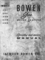
GENERAL
Yoyr new Bowen Gas Water Heater is simple to operate and is built to give
long years of trouble-free performance. However, you will achieve maximum
results if you will first take a few minutes time to read through this manual.
The following operating and service suggestions will increase the utility value
of your heater and better maintain its operating efficiency.
••••• •••••••••••••
PRINCIPLE OF OPERATION
A burning pilot flame playing on the tip of a pilot (thermocouple) actually
generates a minute electrical current (15 10 30 millivolts). This tiny current is
transmitted from the safety pilot to the thermostat valve through a wire leading
from the pilat tip. The wire terminates in a small magnelic assembly "built
into" the thermostat valve. When lighting the pilot (as described in operating
instructions on pages 3 and 4) a plunger which incorporates the master valve seat
and a metal disc is depressed manually to open the valve seat and simultaneously
set the metal disc on the magnet. Aher the pilot has been burning for approximately
one minute, the heat is sufficient to generate the current which flows to the magnet,
the pil.ot current will hold the metol disc down and master valve seat open: Now by
turning the dial to "ON" and setting the temperature dial to the desired temperature, the main gas burner will come on and automatically cycle the burner to maintain Ihe temperature selling of the thermostat. The pilot now is holding the metal
disc: down and the mosier valve seal open, and gas is allowed to pass through
the temperature dial and pilot adjustment seot. The thermostat now opens
ond doses by actuation from the element (rod extending into the tonk and
water) as the water is heated or becomes cool. Gas is b~ing metered to the
pilot through the pilot adjustment seat and the unit will, therefore, continue
to operate automatically. If the pilot flame is extinguished, the thermocouple
(pilot tip) will cool, stop generating its tiny electrical current, and the magnetic
field will foil to hold the metal disc down and it will be released under the
spring tension to dose the master valve seat. The gas will now be totally shut
off to both the burner and pUOI. (Known as 100% shut off).
SEE INSTRUCTIONS fOR liGHTING OR
RELIGHTING EASY TO fOllOW STEP IY
STEP WITH ILLUSTRATIONs. PAGES 314
PAGE 1
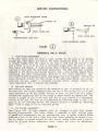
YOUR BOWEN GAS WATER HEATER ("G" SERIES EXCEPT MODEL "G".llaT & "G".I06TI
..
IS EQUlPf,ED WITH EITHER A. M.... XlfROL 01 MINNE....POLIS-HONEYWELl IEGUl"TOI
If it is a ftlaxilrol rCRullltor, follow instructions in service manual, page 7. para·
graph 6 and 7 and refer to illustration on page 6.
If it is II Minneapolis-Honeywell regulator, follow instructWnll and refer to
tratiom appearing on this page.
illUll-
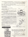
ADJUSTMENTS
Adjust the oullet pressure as follows:
Fig. 2
BEFORE STARTING. TURN OFF THE GAS TO THE
APPLIANCE MANIFOLD.
1. Connect a properly-su.ed manometer Or other
accurate pressure gage at the test-gage tapping furnished by the appliance manufacturer downstream
from all gas controls.
2. Turn on the gas and Ught the bW'ner(s).
3. Unscrew and remove the regulalor cap (V5172A
and B) FIg.2. or the changeovermechanism(V5172C).
Fig. 3.
o
4. Turn the adjusting screw slowly until the manometer indicates the pressure required. (See aragraph 6. page 7 of Service Manual). Tur
ockwise 0
to· rea
ure'
n r
"
to decrease prcB.'1ure.
5. Replace the cap or changeover mechanism, lurn
off the gas, disconnect the manometer, and plug the
test-gage tapping.
PRESSURE REGULATOR CQNVERSION(V5172C only)
CrOSs-8ectlO1l of V5172A or B.
::.~ 1:)
To change the regulator from L P to natural gas depress the regulator convertor with screwdriver and.
turn counterclockw1se 1"\ (Fig. 3). To change from
natural to LP, depress and turn clockwise
~-~
JI:<U..,OIl
AD.LosTHi S(lI(\lI
NOTE: Be sW'e system Is operating properly before
leaving job.
REGULATOR AS INSTALLED
~~0
Pressure Regulator Changeover (V5172C).
o
INSTRUCTIONS TO DISASSEMBLE
A
.0.
1.
Hold half union
(Do nol turn)
2.
Turn B with wrench while hold·
ing A stationary.
clockwise
PAGE 2
with wrench
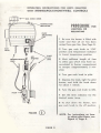
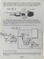
OPERATING INSTRUCTIONS fOR UNITS EQUIPPED
WITH MINNEAPOLIS-HONEYWELL CONTROLS
___ GAS COCK KNOB
~ TEMPERATURE
PROCEDURE
FOR
LIGHTING OR
RELIGHTING
, ,
PilOT
ADJUSTING
I •
CAP
1 Be sure the heater is filled with
water and that all air has been
vented from gas line. (See Page 5).
f
GAS
2 Turn gas cock knob ta "Off"
position and temperature indicator
to lowest temperature position.
INlET
3 Wait sufficient length of time
to allow gas which may have accumulated in burner compartment
to escape. (Approximately 5 minutes).
THERMOCOUPlE
lEAD
\1
J
~
l
~
l
\....
\
4 Turn gos cock knob to pilot.
5 Depress the knob, light the pilot
burner, and hold the knob down
for about 1 minute.
"=-........'~=>.I ,
6 Turn the gas cock knob to ON.
PilOT
7 Set the lever indicator for the
desired water temp.
8 To shut down the heater, turn
gas cock knob to the off position.
FIGURE
(3)
NOTE: For instructions on how
to adjust pilot flame, see
Figure 4, Page 5.
PAGE 3
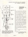
OPERATING INSTRUCTIONS FOR UNITS EQUIPPED
WITH GENERAL CONTROLS
I
PROCEDURE
TOP DIAL
I
fOR
LIGHTING OR
RELIGHTING
TEMPERATURE
DIAL
t
PILOT
ADJUSTING
CAP
A
/§
THERMOCOUPLE
LEAO
~
\IJ
i
SHUTTER
AOR
I
~§
2 Turn top dial to "Off" position, and temperature dial to lowest temperature position.
3 Wait sufficient length of time
to ollow gas which mdy have ac-
~
cumulated in burner comportment
to escape. (Approx. 5 min.)
PILOT
~GAS
UNE
!
!
......
--
1 Be sure that heater is filled with
waler and that all air hos been
vented from gas line. (See Poge 5).
FIGURE
0
~
PILOT
4 Turn top dial to "light Pilot" and
continue turning until dial "Stops."
Hold in this position while lighting.
5 Allow pilot to burn opproximateIy one minute before releasing dial
from stop. If pilot does not remain
ignited, repeat above operations
allowing longer period before releasing from DIAL STOP.
6 Turn lOp di.ol
10 "On" position
and turn temperoture diol to desired position. The moin burner will
ignite.
7 To shut down heoler, lurn .top
dial to "Off."
WHEN ORDERING REPLACEMENT
CONTROLS BE SURE TO GIVE
NAME AND MODEL NUMBER OF
YOUR PRESENT CONTROL.
NOTE: For instructions on how
to adjust pilot flame, see·
Figure 4, Page 5.
PAGE 4
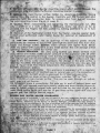
SERVICE INSTRUCTIONS
PILOT MOUNTING SCIEW
®
O....NGE TIP
~
t '''0' "AM' "'",
PILOT flAME &lUE
THEIMOCOUPU LOCK NUT
PILOT MOUNTING SCaEW
0
FIGURE
•
GENERAL MC-3 PILOT
1
PIlOt fL...ME ADJUSTMENT
If the pilot flame does not have a small orange tip the pilot is not getting
enough gas. (See Figure 4·A above). The flame should be about If., of an inch
in vertical height when the water in the tonk is cold and the burner is off
and a flame ~ to
of an inch in horizontal length when the tank is warm.
(See Figure 4-8 above). A large orange flame indicoles excellive gas supply
resulting in short pilot life and early replacement. The pilot has been properly
adjusted at the factory and should operate with a blue orange tipped flame
enveloping the pilot thermocouple. Itemoval of the "pilot adjustment cop"
will reveal the pilot adjustment Krew. (See pages 3 & 4 fOr' location). Turning this
Krew clock-wise reduces the flow of gas to the pilot (blue flame) and counter
clock·wise the gas supply is increased (orange flame). Always replace the
"pilot adjustment cop" to prevent gas leakage.
*
2
GAS LINE VENTING
Most failures to light are caused by the absence of gas, Or' presence of air, at
Ihe pilot port. This usually happens when the unit is new or has run aut of gas.
Upon restoration of the gas supply, the line, or lines, are full of air. It is recommended that appliances sUj:h as the range or space neoler be lighled first. This
allures a supply of gas in the main gas line. If your conlrol is a Honeywell,
venting of the gas line may be accomplished by following sleps " and 5 on
page 3, for on extended period. The General Control is vented by following
steps" and 5, page 4, for on extended period.
3
Alit SHUTTU ...OJUSTMENT
(See. Figure. 5·B). All fuels depend upon air (oxygen) to give Ihem proper
burning. characteristics. This waler heater is required to burn varying types
01 gosef and consequently the air requirements vary. A yellow smoking flame
. indicates a lock of air and a noisy hard blue flame indicates on excess of air.
-The air shutler is rotated around the main burner orifice holder and is held in
place by ~ ..small shutter adjustment screw. Loosen the suew for adjustment.
PAGE 5
A good melhod of adjusting the air shutler is to rolale the shutler dosed far
enough for yellow lipping to occu~ on the main burner. (not pilol) and lhen
slowly open t:1e air shutter until all signs of yellow lipping are gone. When
proper adjJstmenl has been oblained. lighten screw holding air shutler.
FIGURE
5
4
OItI'ICE
CD B
Alit SHUnElt
SlT SCltlW
HOlDl';'~:::;~~==:
IUINIl & PilOT ASSEMILY REMOVAL IN CASE OF ClEANING OR REPLACEMENT
A. It is conceivable that upon removo!ll of the burner and pilot assembly,
damage could mis-align the component po!Irts. Such mal alignment could easily
render the unit inoperative or unstable. Care should always be taken 10 handle
these po!lrh with extreme care.
B. Remove lower panel by turning the slot headed nuts one-half turn.
FIGURE
(D~A~=.C=~.=:::[r~~lt=~
:
FIGURE
(DC
•
•
•
•
C. Turn off the gas supply.
D. Wilh a wrench, unscrew the pi,lol (#2) and thermocouple (#3) nuts where
they are joined 10 the thermoslat. (See Figure 5-A). (Do not remove gas tube
at the pilot).
PAGE 6
. . . . . """'of'
'.
';.~7l~4
l~ . . . . . . . .
~,.-,'-"
j"
~W <-A)
(burnet m~nting screw) which
;
IU.llnd holds the'l)urner l')1ounting bracket in pl~
, .
burner orifice holder by detaching tr~he tubing
nOm !,e control to the burrer. Carefully_ pull The 6urner and pilot
:v,..lssembly:fllb'n the combustion tube. To rerT1,Pve pilot fro~ blJrper, unscrew
> .the pilot. mounting 'screw (figure 4, page 5).
" .
," 'J
.. G. Clutian: When reassembling and flghlening Ihe thermocouple nut, (#3)
only II small (3 or 4 inch) ~wrench is ~ssary. Screw nUl< down as far as
possibJ" .with the fingers. Set lock ~asher by making lldditionlll 14 or Y, turn
with wrehch.
.
_tt. Removal of Ihe thermostat confrol from the healer, requires special tools.
~onsult your authorized water heater dealer for removal or replacement of
. ·"ft\is· part.
"
,
.... '
. .
-'
t 5
CAli AND CLEANING:
The air openings in the exterior panels should
t'~riodically be checked to assure'that opening!"are clean aod free from dust,
lea'ttes and foreign matter. Ceutlon: Clean orifices with lighter fluid. t-Jever
... cle.-n any orifice with a pin, wire or any metal device~this will damage orifice
\.: openings, !flaking it unsafe for further use.
.
6 HE5S\l1E REGULATION: All units using ·bollied gas (Black Orifice) must
ca;n, eleven (11) inches wateJ' column pressure at the appliance with all other
. gas appliances operating (burning). Units burning nafu~gas must be equipped
wilh natural gas main burner orifice (color: natural br."or yellow) and regulaf!d to 3}!2 inches water column pressure. No change in the pilot orifice is
r';"ired. How!ver, the safety pilot must be readjusted for any new gas. See
page 5, figure 4 on Pilot Flame Adjustment. (For complete details, write for
•• !o>
BOWEN Info-Gram #S6A.)
7 'CONVERSION'INSTRUCTIONS, This appliance is equipped wifh a regulator
convertible fOf'~'lJ1e with LP (battled) gas or natural gas, with the exception of
models #G·lIOT, G- J 06T which is approved for lP (baffled) gas only.
'NOTE~RKING on lever at fop of regulator; whether "lP" or "Nat".
NOTE COLOR of main burner orifice. This can be seen through air adjustment aperture on burner.
TO tON\lfRT, place a screwdriver, flat side up, in end of lockout lever and
swing 18ct' until desired markingtfs plainly visible and lever lies .flat (figure 5c,
page 6). lo51all orifice of proper color and drill size for the kind of gas to be
used. Brad!. orifice (#58 drill size for LP gas) Brass orifice (#49 drill size) for'
. patUfar ga'. See Servtce Manual, Pal. 6,
~
..-..:f1l4: r: . . . tfie:-main
~
,.,.•• ,~lucnn9
~
BOWEN GAS WATER HEATER GUARANTEE
>
Thil w~t.r heatltr- i.' warranted ~ any port or paru of thil unit, e~Qfpl "hI!, controls, which in
OUr iu~ment .haw evicence of defect will be repaired or replaced ~augh c Bowen Water
H _ holer, Oillribulor or the factory at Wixom, Michigan, prollided thot soid product
r. .l.'ft":"d .with.. th. manuf'«l':/rer .01 the lime of purchale and fYrlher prOVided lhot the def«tive
~ 11jO'l1 b. r'lurned to the deafer, di.tribulor or the factory 01 Wixom, Michigan, tronlporlotion-~prell'OW.,wilhirr.p"eyear from the dote of .ole and regiltration.
Th1e wlh~~ "011 not oPply,"'lH Can we o ..ume any responsibilily for conleqyenliol damages
tflot might ....
fr1lm ill Ule, mi....se, Or imp.-oper inllollotion, where the pradvcr hoi been
wITh trl'otteredln on.,. way or which in our iudgmenl hot been lubjected to milule,
.....or ~:;".~9' which hoi the seriol number efJacecl, altered or remolled.
to ~'ihe 1I0roge -,gnlt due to excelli~ depcnit of foreign moiler .hall not be CO!'ltrued
in t~nk mot.r'al or warkmonship.
U~
0,... bce.. Prell...:'e Relief Vallie in conjunction with the operation of thil tieater
t e ~1Ity of tonk;
"'" t
..
.N.-OC
~ r.pr,tlntatille il authorized to molte ony worr\lntv' or ~lIume onY'};obility not
r y ill
""ith the f,.golng.
"fl
.1
fle
t-
.
,m
O<§:'
. ...
/...
~
,~
·1J:-io;J>:1-.,...~
,
..
,.lotl£f.',..".,-,,,.
'PAGE 7
I