1
.
1987 Arctic Cat"
Kitty Cat,m
Illustrated Parts and
Service Manual
ARCTIC CAT"
4~~,;t:
Certi fied Parts Corporation
r
,
TABLE OF
CONTENTS
Page
1. General Information
2. Engine
(
c
1·8
9·23
3. Fuel System
25·30
4. Electrical System
31·36
5. Recoil Starter
37·40
6. Service Parts
41·54
-
SECTION 1
-
GENERAL INFORMATION
TABLE OF
CONTENTS
Spec if ications .... . .... ... . .. ... . ....... . .. 2
Engine Break-In ...... . . . ............ . ...... 2
Recommended Gasoline .... . ............... 2
Recommended Oil ............. ... . . .... .... 3
Summer Storage .......... . .. . . . ........... 3
Preparation After Storage .. ...... .. . ......... 3
Lubrication ......... . .... . ....... . ......... 4
Brake ...................... . ..... . .... . ... 5
Track Tension ........... . .. . . . ....... .. ... 5
Track Alignment ........................... 6
Ski Alignment ..... . ....................... . 6
Steering Alignment ..... . . ... ... . . . ......... 7
Ski Wear-Bar .................. . ............ 7
1
,
Specifications *
ENGINE AND DRIVE
Model
AA06A8
Bore x Stroke
41 x 45 mm (1.614 x 1.772 in.)
Displacement
59 cc (3.60 cu in.)
Compress ion Ratio
6.6:1
Drive Clutch
Centrifuga l
Brake Type
Band
Igniti on Type
CO l
Track Width
25.4 cm (10 in .)
Track Length on Ground
35.6 cm (14 in.)
Track Tension (range)
20·25 mm (3/4·1 in.)
Spark Plug
NGK BR6HS
Spark Plug Gap
0.7 mm (0.028 in.)
Ignit ion Timing
20° BTDC - 1.728 mm (0.068 in.)
MISCELLANY
Gasoline
88 Minimum Octane Leaded or Unleaded
Engine Oil
Arctco/Arctic Cat 50:1 Oil
Fu el Mixture for Break-In
24:1
Fuel Mixture after Break·ln
50:1
Fuel Tank Capacity
1.7 I (0.46 U.S. gal.)
Gear Case Lubri cant
SAE #10W-30
Length wlSkis
142.2 cm (56 in.)
Height
72.4 cm (28.5 in.)
Overall Width
58.4 cm (23 in.)
Dry Weight
45 kg (102 lti)
·Specifications subject to change without notice.
Engine Break·ln
The Kitty Cat Snowmobile engine (when new or
overhauled) requires a short break-in period (approximately 10 operating hours or two tankfuls of
a 24:1 fuel mixture) before being subjected to
heavy load cond itions or full-throttle operation.
Strict adherence to the break-in procedure will
contribute to optimum performance and longevity
of the engine.
During break-in, a maximum of 1/2 throttle is recommended; however, brief full-throttle acce lerations and variations in driving speeds contribute
to good engine break-in.
2
Recommended
Gasoline
The correct gasoline is 88 minimum octane leaded. Do not use gaolin es containing either methano l or more than 5% ethanol.
•
CAUTION
•
Do not use gasolines containing either methanol
or more than 5% ethanol. Also, gasoline additives and white gas MUST NOT BE USED; they
will eventually cause engine damage.
spark plug; then remove the spark plug. Pour
15 ml (1/2 fl oz) of petroleum-based oil into the
spark plug hole; then pull the recoil starter
handle slow ly about ten times. Install the ·
spark plug and connect the high tension wire.
NOTE: Arctco recommends leaded gasoline;
II however,
unleaded gasoline (of at least 88
minimum octane) may be used as a substitute if
leaded gasoline is not available.
r
6.
Recommended Oil
Remove the drive chain and clean thoroughly
in a solvent. Install drive chain and lubricate
with a dry, graphite-based chain lubricant.
NOTE: The drive chain is equipped with a
II master
link for servicing.
The correct oils to use are either Arctco 50:1 Oil or
Arctic Cat 50:1 Oil. These oils are specially formulated to meet the lubrication requirements of
the Kitty Cat engine.
7.
Apply a lightweight, petroleum-based oil to
the stee ring post bushings. Check the lubricant level in the gear case and add lubricant if
necessary.
8.
Tighten all screws, nuts, and bolts making
sure that all calibrated nuts and bolts are
tightened to specifications.
9.
Make sure all rivets holding components
together are tight. Replace all loose rivets.
r
Summer Storage
•
CAUTION
•
Prior to storing the Kitty Cat for the summer, it is
extremely important that it be properly serviced
to prevent rusting and component deterioration.
Arctco recommends the following procedure to
prepare the snowmobile for summer storage.
1.
2.
3.
Remove the seat cushion from the tunnel,
wash with a damp cloth, and store in a dry
place.
Clean the snowmobi le thoroughly by hosing
dirt, oil, grass, and other foreign matter from
the underframe, tunnel, hood, and belly pan .
Allow the snowmobile to dry thoroughly. DO
NOT get water into any part of the engine.
Drain al l fuel from the fuel tank. Close the fuel
shut-of valve by rotating it clockwise; then
remove the air intake cover. Start the engine
and allow it to idl e; then using a ru st-preventative oil, rapidly inject the oil into the carburetor air intake for a period of 10 to 20
seconds until all fuel in the carburetor float
bowl is used and the engine stops. This procedure will coat the crankshaft with a protective coating of oil. Install the air intake cover
and the fuel tank cap (if it was removed).
4.
Plug the hole in the muffler with a clean cloth.
5.
Disconnect the high t ensi on wire from the
10. Clean and polish the hood, console, and
chassis with an automotive-type cleaner wax.
DO NOT USE SOLVENTS OR SPRAY CLEANERS. THE PROPELLENT WILL DAMAG E THE
FINISH .
11. Lightly sand the bottom of the skis; then using black paint pIn 0652-004, paint the entire
bottom of the skis.
12. If possible, store the Kitty Cat indoors. Raise
the rear of the snowmobile off the floor and
block up the rear end. Cover the snowmobile
with either a machine cover or heavy tarpaulin
to protect it from dirt and dust.
13. If the Kitty Cat must be stored outdoors, block
the entire snowmobile off the ground and
cover it with either a machine cover or heavy
tarpaulin to protect it from dirt, dust, and rain.
Avoid
II NOTE:
moisture will
using a plastic cover as
collect on the snowmobile
causing rusting.
r
Preparation
After Storage
\..
Tak ing the snowmobile out of summer storage
and correctly preparing it for another season will
assure many miles and hours of trouble-free
snowmobiling . Arctco recommends the following
procedu re to prepare the snowmobile.
3
1.
Clean the snowmobile thoroughly. Polish the
exterior of the snowmobile using an automotive-type cleaner wax.
2.
Clean the engine coo ling fins and the recoil
starter vents . Remove the cloth from the muffler.
3.
Check all control wires and cables for signs
of wear or fraying. Replace if necessary. Use
cable ties or tape to route wires and cab les
away from hot or rotating parts.
4.
In spect the drive chain and drive chain tensioner. Repface if necessary.
5.
Lubricate the drive chain and steering post
bushings.
6.
Check brake-lever travel distance, all con trols, ski alignment, track tension, track al ignment, brake band, and ski wear-bars; adjust or
replace as necessary.
7.
Examine the fuel filter and clean or replace if
necessary.
8.
Fi ll the fuel tank with properly mixed fuel.
9.
Clean and in stall the seat cushion .
10. Check the spark plug (clean or replace as
necessary); then start the engine and ensure
proper carburetor adjustments.
If excessive dirt is present on the drive chain,
c lean using the following procedure:
1.
Remove the drive chain shield.
2.
Remove the master link from the drive chain;
then remove the chain.
3.
Wash the drive chain in parts cleaning solvent
and dry using compressed air.
4.
Place the chain into position on the clutch
sprocket, loop the chain over the driven
sprocket, and in sta ll the master link making
sure that the c lip open end is directed away
from the direction of drive chain rotation and
that the clip is seated properly.
III
NOTE: Make sure the chain is resting on the
chain tensioner and proper chain tension is
maintained.
5.
Lubricate the drive chain with dry, graphitebased chain lubricant.
6.
Install the drive chain shie ld.
III
NOTE: If a dry, graphite-based chain lubricant is not available, lubricate the drive
chain with several drops of petroleum-based oil. If
the Kitty Cat is operated in the summer with the
optional wheel kit, the drive chain should be
lubricated more frequently.
STEERING POST BUSHINGS
Apply a lightweight, petroleum-based oil to the
upper and lower steering post bushings every 40
operating hours.
Lubrication
The drive chain and steering post bushings must
be properly lubricated to ensure efficient operation. Also, the gear case lubricant must be maintained at the proper level.
GEAR CASE
Every 40 operating hours the lubricant level
should be checked in the gear case. To check the
lubricant level, remove the oil level screw from the
lower side of the gear case. The lubricant must be
at the pOint of overflowing in the oil level hole. If
lubricant is not present, add SAE # 10W-30
through the oil fill hole until it flows out of the oil
level hole.
DRIVE CHAIN
The drive chain should be lubricated every 20
operating hours with a dry, graphite-based chain
lubricant. By using a dry, graphite-based chain
lubricant, dirt buildup on the drive chain will be
minimized. Before each lubrication, inspect the
drive chain for dirt accumulation .
To lubricate the drive chain, shut the engine off
and wait for all moving parts to stop, remove the
drive chain shield, and lubricate the drive chain.
After lubricating the drive chain, install the drive
chain shield.
4
Fig. 1·1
Oil Fill
0726·196
r
NOTE: The brake band should lock tightly
II when
the brake lever is compressed and
c,
should disengage when the lever is released. If
additional adjustment is necessary, use the
following steps.
Brake
'-------------------------~
1.
Loosen the rearward flange nut on the brake
cable.
Checking Brake Lever Travel
1.
Compress the brake lever fully.
2.
2.
Check the distance between the brake lever
and the lever stop. The distance must be
within the specified range of 6-13 mm (1/4-1/2
in.).
Tighten the forward flange nut to set up the
brake.
3.
Ensure correct brake lever travel distance;
then tighten the rearward flange nut to secure
the adjustment.
Fig. 1-2
r
Track Tension
Track tension and track alignment are
II NOTE:
interrelated; therefore, always check both,
0725·565
3.
If travel distance is not as specified, adjust
the brake.
Adjusting Brake Lever Travel
To adjust the brake lever travel, use the following
procedure:
1.
Remove the drive chain shield.
2.
Loosen the jam nut on the retaining pin; then
tighten the retaining pin to set up tile brake.
even if only one adjustment seems necessary.
Track tension is directly related to the ovEtrall performance of the snowmobile. If the track is too
loose, it may slap against the tunnel causing
wear, or it may ratchet on the track drive
sprockets. If tile track is too tight, track drive
sprocket wear will result. In addition, a track that
has improper tension will prevent the snowmobile
from reaching optimum performance.
Checking Track Tension
6
WARNING
& '
00 NOT attempt to check or adjust track tension
with engine running : Turn ignition key to the OFF
position. Personal" injury could result froni contact with a rotating track .
Rearward
Flange Nut
Before checking track tension, remove excess ice and snow buildup from the track and
from the track drive sprockets.
2.
Raise the rear of the snowmobile off the floor
making sure the track is not contacting the
floor.
3.
Exert moderate downward pressure at midspan of the lower track section. Measure the
distance between the bottom of the rear
bogie wheels and the inside surface of tl<l'e
track. The measurement must be within a
Retaining Pin
0725·634
3.
- 1.
Check the brake lever travel di stance
periodically while tightening the retaining
pin. When the distance is within the specified
range of 6-13 mm (1/4-1/2 in.), tighten the jam
nut on the retaining pin to secure the adjustment.
5
range of 20-25 mm (3/4-1 in .). If th e measure·
ment is not as specified, an adjustment is
necessary.
II NOTE: Allow the track to coast to a stop. DO
NOT apply the brake because it could pro·
duce an inaccurate alignment condition.
Adjusting Track Tension
1.
to rotate the track severa l revolutions. SHUT
ENGINE OFF.
Loosen the ax le bolts on both ends of the ax·
Ie.
5.
When the track stops rotating, check the
track alignment and continue adjusting until
proper alignment is attained.
6.
Tighten the axle bolt to 2.8-3.3 kg·m (20-24 ft·
Ib).
7.
Fie ld test the track under actual conditions;
then verify correct track alignment.
Fig. 1-4
NOTE: After adjusting track alignment, be
II sure
correct track tension has been main·
tained.
Axle Bolt
0725·531
2.
Adjust the tensioner lock nuts on both sides
of the track until the proper track tension is
attained. Make sure to adjust both lock nuts
equally.
3.
When track tension is correct, tighten axle
bolts to 2.8-3.3 kg-m (20-24 ft-Ib).
J
( ___T_r_a_C_k_A_Ii_g_n_m_e_n_t__
r
Ski Alignment
Checking Ski Alignment
1.
Turn the handl ebar to the straight-ahead posi tion.
2.
Measure the distances to the outside edges
of the leaf springs. Make sure the measure·
ments are taken behind the front mount
bracket and ahead of the rear mount bracket.
Fig.1·S
Proper track alignment is obtained when the rear
track drive sprockets are centered in the track
cutouts. If the track runs to the right or left of .
center, an adjustment is necessary.
Adjusting Track Alignment
1.
Before adjusting track alignment, remove ex·
cess ice and snow buildup from the track and
track drive sprockets.
2.
Raise the rear of the snowmobile off the floor
making sure the track is free to rotate.
Right Spindle Crank
Front
Tie Rod - -+--i1
Left Spindle Crank
0725·621
3.
4.
6
If the track runs to the right, loosen the right·
side axle bolt and tighten the right·side tensioner lock nut one revolution. If the track
runs to the left, loosen the left-side axle bolt
and tighten the left·side tensioner lock nut
one revolution.
Start the engine and accelerate only enough
NOTE: Ski alignment is correct when the
II skis
are parallel to each other (equal
measurements front and rear) or when the skis
have a maximum of 6 mm (1/4 in.) "toe out" (front
measurement 6 mm (1/4 in.) more than rear
measurement).
-
c
3.
If sk i alignment is not as . specified, the
snowmobile will have a tendency to wander
and may be difficult to control; therefore, an
adjustment is necessary.
Steering Alignment
Adjusting Ski Alignment
1.
Make sure the ignition key is in the OFF position.
2.
Visually examine to determine whi c h ski is
out of alignment with respect to the handlebar; then make adjustment to that ski.
3.
Open the hood and loosen the front ti e rod
jam nut of the ski to be aligned.
4.
Remove the lock nut securing the front tie rod
ball joint to the spindle crank; then separate
the ball joint from the spi ndle crank.
Fig. 1·S
Steering Tie Rod
Ball Joint
Front Tie Rod
Ball Joint
1.
Open the hood and loosen the steering tie rod
jam nut.
2.
Remove the lock nut securing the steering tie
rod ball joint to the spindle crank. Separate
the steering tie rod and ball joint from the
spindle crank.
3.
Place the handlebar and skis in the straightahead position .
4.
Rotate the ball joint until the ball joint stud
al ign s with the hole in the spindle cran~; then
secure the ball joint to spindle crank with the
lock nut.
NOTE: There should be approximately an
II equal
number of threads showing on both
(
RIGHT·SIDE VIEW
0726·198
5.
Align the sk i; then rotate the ball joint until
the ball joint stud aligns with the hole in the
spindle crank and insert the ball joint stud into the spindle crank.
6.
Install the lock nut on the ball joint stud and
secure.
7.
Tighten the front tie rod jam nut and affirm
the correct alignment.
NOTE: There should be approximately an
II equal
number of threads showing on both
ends of the front tie rod. If more threads are showing on one end than on the other, the jam nuts can
be loosened and the tie rod rotated until thread
equality is attained (this process will not affect
ski alignment). Tighten the jam nuts securely.
r
Visually examine the steering alignment by ~I~c
ing the handlebar in the straight-.a head PO~lt~on
and checking to be sure the skis are pOinting
straight ahead. If the skis are not pointing straight
ahead, adjust using the following procedure:
ends of the steering tie rod. If more threads are
showing on one end than on the other, the jam
nuts can be loosened and the tie rod rotated until
thread equally is attained (this process will not affect steering alignment). Tighten the jam nuts
securely.
5.
Tighten the steering tie rod jam nut.
Ski Wear-Bar
The ski wear-bar is a replaceable bar attached to
the underside of the ski. The purpose of the wearbar is to ass ist in turning the snowmobile, to
minimize ski wear, and to maintain good steering
control. If the snowmobile is operated primarily in
deep snow, ski wear-bar wear will be minimal;
however, if the snowmobile is operated on terrain
where the snow cover is minimal, the ski wear-bar
will wea~ faster.
Removing Ski Wear-Bar
1.
Remove ice and snow buildup from the ski.
7
2.
With the fuel tank nearly empty (less than 1/4
full), lay the snowmobile on its side. A piece
of cardboard should be used to protect the
finish on the hood.
3.
Remove the lock nut and washer securing the
wear-bar to the ski.
Fig. 1·7
Lock Nut
0725·071
4.
Either pryor pull the center of the wear-bar
away from the ski until the wear-bar bolt is
clear of the ski; then slide the wear-bar forward as far as possible and pull the rear of the
wear-bar from the hole in the rear of the ski.
5.
Remove the wear-bar from the hole in the
front of the ski.
Installing Ski Wear-Bar
1.
Insert the front of the wear-bar into the hole at
the front of the ski and swing the wear-bar
rearward .
&
WARNING
&
DO NOT bend the ski wear-bar excessively when
installing. Excessive bending of the ski wear-bar
may cause premature wear, breakage, and
possible injury.
2.
Slide the wear-bar rearward until it is possible
to insert the rear of the wear-bar into the hole
at the rear of the ski.
3.
Center the wear-bar bolt in its hole and install
the washer and lock nut.
4.
Tighten lock nut securely.
8
r
SECTION 2 - ENGINE
TABLE OF
CONTENTS
Specifications ..... . ....... . . . . ........... 10
Disassembly ......................... . . . . 10
Cleaning and In spec tion .................... 14
Assembly . . ............. . ..... . .... . ... . . 17
Fill Gear Case ...... . . .. . .... . .. ..... . . .. . 23
9
r
Specifications
GENERAL
SPECIFICATJON
Model
Type
No. of Cylinders
Lubrication
Starter System
Bore x Stroke
Displacement
Compression Ratio
Piston Ring End Gap Range
Piston Skirt/Cylinder Clearance Range
Piston Pin Diameter Range
Piston-Pin Bore Diameter Range
Connecting Rod Small End Diameter
Crankshaft Runout
Crankshaft End Play Range
AA06A8
2 Cyc le, Air-Cooled
1
Gas/Oil Mix
Manual Recoil
41 x 45 (1 .614 x 1.772)
59 (3.60)
6.6:1
0.20-0.80 (0.008-0.031)
0.05-0.13 (0.0020-0.005)
11.990-12.000 (0.4720-0.4724)
12.000-12.010 (0.4724-0.4728)
15.99-16.00 (0.6295-0.6303)
0.05 (0.002)
0.05-0.10 (0.002-0.004)
-mm (in .)
cc (cu in.)
- mm (in .)
- mm (in.)
- mm(in .)
- mm(in.)
-mm (in.)
- mm (in.)
- mm (in .)
TORQUE
kg-m
ft-Ib
Cylinder Head Nut
Crankcase Bolts
Flywheel Nut
Intake and Ex haust Nuts
0.8-1.2
0.6-0.9
4.0-5.0
0.8-1.1
6-9
4.5-6.5
29-36
6-8
(~_____D_is_a_s_s_e__m_b_I_Y____~J
then disconnect carburetor rod
spring.
2.
Remove gas tank; then disconnect fuel lines
from carburetor.
rod
3.
Slide gasket, insulator, and gasket off intake
studs.
4.
Remove th e nuts and lock washers securing
muffler. Slide muffler off exhaust stu ds; then
remove exhaust gasket.
Fan/Power Head
1.
and
Fig. 2-2
Remove the nuts and lock washers sec uring
carburetor. Slide carburetor off intake studs;
Fig. 2-1
A778
A779
10
5.
Remove recoil starter.
6.
Remove screws securing fan cover; then
remove cover.
Fig. 2·6
Fig. 2·3
A771
A775
7. Remove cylinder head cowling.
11. Remove piston pin circlips. Remove piston
pin using the Arctic piston pin puller.
Fig. 2·4
Fig. 2·7
r
A774
8. Remove the cylinder head nuts and
washers; lift head off cylinder studs.
12. Remove recoil starter pulley and spacer.
9. Slide head gasket off cylinder studs.
Fig. 2·8
Fig. 2·5
A772
A766
10. Slide cylinder straight upward until free of
piston. Remove base gasket.
13. Remove four countersunk screws securing
fan; then remove fan.
11
Fig. 2-12
Fig. 2·9
•
A764
14. Using a flywheel holder (or equivalent),
remove the flywheel nut.
17. Remove the three screws securing stator
plate to crankcase.
Fig. 2·10
Fig. 2·13
A762
15. Using a flywheel puller, remove the flywheel. Account for the flywheel key.
18. Remove the screws securing ignition coil;
then remove coil.
Fig. 2·1 1
Fig. 2-14
A756
16. Scribe a lin e on the stator plate and the
crankcase . Use these marks during
assemb ly.
12
Gear Case/Crankcase
1. Using an impact screwdriver, remove the
screws securing gear case cover. Lift cover
off crankcase.
6.
In order, remove the centrifugal weight
assembly, primary drive gear, and key from
the crankshaft.
Fig. 2-18
Fig. 2·15
•
A747
A755
7. Using an impact screwdriver, remove the
five screws securing crankcase halves.
2. Remove cover gasket.
3. Remove primary driven shaft and gear from
gear case.
Fig. 2·19
Fig. 2·16
A745
A752
4. Remove shifter from end of engine crankshaft.
8. Carefully separate the crankcase halves.
5. Remove the nut securing primary drive gear
and centrifugal to the crankshaft.
•
Fig. 2·17
CAUnoN
•
DO NOT use chisels; screwdrivers, or any other
instruments to pry cases apart. Any damage to
the crankcase sealing area wII result in an air
leak resulting in severe engine damage.
,
c
A748
13
Fig. 2·21
Fig. 2·20
A737
A742
9. Remove the crankshaft from the crankcase.
10. Thoroughly wash all eng ine components.
Cylinder
1. Remove carbon buildup from the exhaust
port.
NOTE: Use a non-metallic carbon removal
II tool.
2. Wash the cylinder in clean solvent.
r
Cleaning and
Inspection
NOTE: Whenever a part is worn exces·
sively, cracked, defective, or damaged in
II
any way, replacement is necessary.
Cylinder Head
1. Remove any carbon buildup which has col ·
lected in the combustion chamber.
•
CAUTION
•
Use a non-metallic tool to prevent scratching and
scoring of the combustion chamber.
2. Thoroughly clean the cy linder head in cleaning solvent.
3. Inspec t cylinder for pitting, scoring , scuffing, or corrosion. Replace if damaged.
4. To remove minor imperfections or marks in
the cylinder, use a flex hone with 500 grit
stones to clean the bore. Use honing oil for
lubrication. Move hone back and forth so a
"crosshatch" pattern will result.
5. Inspect all thread ed areas for damaged or
stripped thread s.
6. Insert an inside micrometer, cylinder gauge,
or snap gauge into the cylinder bore and take
s ix measurement s of the bore. Measure front
to back and side to side at pOints below in take port, above exhaust port, and 1 cm (0.375
in.) below the top of the cy linder. If measurements vary by more than 0.05 mm (.002
in.), the cylinder is tap ered or out -of-round
and must be replaced.
Fig. 2-22
3. Inspect spark plug threaded area for any
damage.
4. Place the cylinder head on a surface plate
covered with 400 grit "Wetordry" sandpaper.
Move the head in a figure eight motion to
check sealing area for trueness. High spots
can be noted by evidence of a shiny portion on
one areaofthesealing area. Theentiresurface
must have a uniform appearance.
14
0725·586
Piston
1. Remove carbon buildup from dome of piston
using a non-metallic carbon removal tool.
2. Examine the sides of the piston for evidence
of excessive "blow-by ." Excessive "blow-by"
will indicate worn piston rings or an out -of round cylinder.
8. Measure the piston pin approximately 6 mm
(0.250 in.) from each end. Piston pin diameter must be between 11.99-12.00 mm
(0.4720-0.4724 in .).
Fig. 2·25
3. Check the sides and skirts for evidence of
scuffing. To remove minor marks, use 400 grit
"Wetordry" sandpaper and lightly sand the
affected area.
Fig. 2·23
\
A734
~ithin spe~ifica·
NOTE: If piston pin. is not
tions, replace the pIston pm and beanng as
II
a set.
A732
-
4. Check the pistons for signs of cracks in the
piston pin and skirt areas. Replace pi ston if
damage is found .
5. Use a piece of an old ring to clean the ring
grooves. Make sure ring retaining pin is correctly positioned and is in good condition.
6. Insert an inside snap gauge about 6 mm
(0.250 in.) from the outside of the piston pin
bore. Carefully remove the snap gauge .
Piston Skirt Clearance
1. In sert an in side micrometer or snap gauge into the cylinder ju st above the intake port.
Take measurement from front to back.
Fig. 2·26
Fig. 2-24
A729
A733
7. Measure the snap gauge with a micrometer.
Piston pin bore must be 12.00 -12.01 mm
(0.4724-0.4728 in.) .
2. Measure the piston skirt 1 cm (0.375 in .)
above th e bottom of the piston skirt.
15
Crankcase Halves
Fig. 2·27
1. Thoroughly wash halves using cleaning solvent.
2. Inspect halves for scoring, pitting, scuffing,
or any imperfections in the casting.
3. Inspect all threaded areas for damaged or
stripped threads .
Fig. 2·29
A731
3. Subtract the measurement in step 2 from
measurement in step 1. The difference is the
piston skirt clearance and must be 0.05-0.13
mm (0.0020-0.005 in.).
NOTE: If the clearance exceeds the wear
limit the piston must be replaced to bring
II
clearance into acceptable range. However, if
clearance is still excessive, the cylinder will
have to be replaced.
A721
4. Check the bearing areas for signs of cracking
or bearing movement; then check dowel pins
for wear.
Piston Ring End Gap
1. Insert the piston ring about 1 cm (0.375 in.) into the top of the cylinder bore. Position the
ring horizontally in cylinder by pressing the
dome of the piston against the ring .
2. Slide a feeler gauge between the ends of the
ring .
5. Examine the crankcase sealing area. If any
nicks or scratches are found in the sealing
area, correct the surface with the use of a surface plate covered with 400 grit "Wetordry"
sandpaper. Rotate the crankcase in a figure
eight motion until a uniform finish is noted.
Fig. 2·30
Fig. 2-28
A740
A735
3. Piston ring end gap must be 0.20-0.80 mm
(0.008-0.031 in.). Since the amount of wear at
the ends and center of the piston ring affects the end gap, replace the ring set if the
ring end gap is excessive.
16
Crankshaft
1. Thoroughly wash crankshaft w/bearing in
cleaning solvent.
2. Inspect edges of bearing for external wear,
scoring, and scuffing. Rotate the bearings by
hand to ensure free turning without binding
or roughness.
3. Check the connecting rod using the same
method. If binding or roughness is noted, the
connecting rod, bearing, and crank pin will
have to be replaced.
Fig. 2·33
4. Measure the rod small end diameter using a
snap gauge. Lock the gauge and carefully
remove it.
Fig. 2·31
A741
9. Slowly rotate th e crankshaft and observe the
"total" crankshaft runout. This is the difference between the highest and lowest
readings . Maximum runout must not exceed
0.05 mm (0.002 in .). If runout exceeds specifications, the crankshaft must be straightened
or replaced .
A726
5. Measure the snap gauge with a micrometer. The diameter must be 15.99-16.00 mm
(0.6295-0.6303 in.). If diameter is not within
specifications, the connecting rod must be
replaced.
Fig. 2·32
r
Assembly
A727
6. Check the crankshaft runout on a setup as
shown using a surface plate, V-blocks, and a
dial indicator with a mounting base.
7. Support the crankshaft on the bearings or the
shaft itself.
8. Mount the dial indicator against the
crankshaft at the area of the oil seals. Be sure
that the crankshaft is clean.
Crankcase/Gear Case
1. If bearings were removed, install bearings
into crankcase halves.
2. Using a seal installing tool, insert seals in
crankcase halves.
NOTE: Make sure spring side of seal is
toward center of crankshaft.
II positioned
3. Apply grease to the inner lips of the seals.
17
Fig. 2·37
Fig. 2·34
-A745
A744
4. Press crankshaft into magneto side of case .
NOTE: Place rubber band over connecting
rod to prevent rod from damaging cases if
engine is accidently rotated.
II
Fig. 2·35
8. Install a woodruff key in the PTO end of the
engine crankshaft. Slide drive gear onto
crankshaft so the large beveled edge is
posit ioned inward.
Fig. 2·38
A742
5. Apply RTV to both halves of th e crankcase.
Fig. 2·36
A746
9. Place centrifugal onto PTO end of crankshaft making sure notch of centrifugal
aligns with keyway of crankshaft.
Fig. 2·39
A743
6. Install crankcase dowel pins if they were removed.
7. Apply blue Loc-Tite to the five screws that
secure crankcase; assemble cases; then
tighten screws using an impact screwdriver.
18
•
..
A747
10. Secure PTO end crankshaft components by
applying Loc-Tite to the nut, installing the
nut, and tightening nut to 30-40 nom (22-29 ftIb).
13. Install the primary driven shaft.
Fig. 2-43
/
A752
A749
11. Install shifter so centrifugal weights are
positioned against shifter arms.
14. Apply RTV to both sides of the gear case
gasket. Place gasket against crankcase.
Fig. 2-44
A750
12. Install bearing in gear case housing. Apply
grease to the inner lips of the seal; then
place seal in position .
Fig. 2·42
A753
15. Install cover w/output shaft. Install five
screws; then tighten screws with impact
screwdriver. Fill gear case.
Fig. 2-45
A751
A755
19
Electrical System
1. Move ignition coil into position; then secure
with two screws and lock washers. Connect
coil lead to lead from magneto.
Fig. 2·46
4. Make sure flywheel magnets are clean . Align
keyway of flywheel with key in crankshaft.
Place flywheel on crankshaft.
5. Install flywheel flat washer, lock washer,
and nut. Using a flywheel holder, tighten nut
to 4.0-5.0 kg-m (29-36 ft-Ib).
Fig. 2·49
A763
2. To in sta ll mag neto baseplate, align the
scribe marks made during assembly. Apply
Loc-Tite to the three sc rews; then tighten
sc rews sec urely.
6. Move flywheel fan into position . Apply LbcTite to the four mounting scre ws. In stall and
tighten screws using an impact screwdriver.
Fig. 2·50
A764
3. Place flywh eel key in position.
7. In stall starter pulley and spacer. Secure with
three sc rews and ti ghten secu rely.
Fig. 2·48
Fig. 2·51
A 766
20
Power Head/Fan
1. Place the bearing in the connecting rod
smal l end. Apply engine assembl y oil to the
bearing.
4. Install piston pin. Secure piston pin with
circlips .
Fig. 2·55
Fig. 2·52
A769
A767
2. Install the piston rings . The letter near the
ring end must be positioned upward. Make
sure ring ends are pos itioned correctly over
piston ring keepers .
Fig. 2·53
NOTE: Make sure open end of both circlips
is directed toward either the piston top or
II
bottom.
5. Applya thin coat of RTV to both sides of the
cylinder base gasket; then install base
gasket.
Fig. 2·56
A770
A736
3. Place the piston assembly onto the con ·
necting rod. Make sure arrow on dome of
piston points to the exhaust side of the
engine.
Fig. 2·54
6. Using a piston holder to "square" the
piston, compress the piston rings and in·
stall the cylinder. Do not force cylinder. If
cylinder binds, remove, check piston rings,
and install.
Fig. 2·57
A771
21
7. Place head gasket in position.
11. Install fan cover and secure with four
screws. Make sure high tension coil lead is
secured by upper rear screw.
Fig. 2·58
Fig. 2·61
A772
A775
8. Place cylinder head in position. Head must be
positioned so the cooling air flow is parallel to
fi n pattern.
9. Tighten cylinder head nuts to 8-12 n-m (6-9
12. Install recoil starter. Just before tightening
screws, pull recoil rope and hold to center
recoil; then tighten screws securely.
Fig. 2·62
ft-Ib).
Fig. 2·59
--.
A776
A773
13. Install exhaust gasket; then place muffler
10. Install head cowling and fasten securely.
Fig. 2·60
Fig. 2·63
A774
22
onto exhaust studs . Secure muffler with
two nuts and lock washers; tighten nuts to
8-11 n-m (6-8 ft-Ib).
A778
14. Install spark plug; then tighten to 25-28 nom
(18-20 ft-Ib).
,
. ~
Fill Gear Case
15. In order, place a gasket, insulator, and
gasket onto the intake studs.
Fig. 2-64
1. Remove the oil fill plug located on the top of
the gear case cover.
2. Remove the oil level screw from the lower
side of the gear case cover.
3. Add SAE 10W-30 lubricant until fluid flows
out oil level hole.
Fig. 2-66
A777
16. Connect carburetor rod and rod spring to
the throttle control lever and the carburetor
throttle plate.
17. Slide carburetor onto the intake studs; then
secure with two nuts and lock washers.
Tighten nuts to 8-11 nom (6-8 ft-Ib).
Fig. 2-65
A806
4. Install the oil level screw .
5. Install the oil fill plug .
A779
23
.-
I--.J
SECTION 3 - FUEL SYSTEM
TABLE OF
CONTENTS
•
c
Specifications ..................... .. . . .. . 26
Removal and Disassemb ly .... . . .. . . . . .. .... 26
Cleaning ................................. 27
Inspection ... . ........... . .......... . .... 28
Assembly and Installation ........ ......... . 28
Adjusting .. ........ . ................. . ... 30
Throttle Stop Screw ..................... . 30
Air Screw .... . . ....... . .. . .......... ... 30
Throttle Cab le ..... . . . .. . ... . ........... 30
Fuel Fi lter .... . ........................... 30
25
3.
r
Specifications
Slide carburetor off intake studs; then
disconnect the throttle rod and spring from
governor arm. Disconnect rod from carburetor.
4. Remove the two nuts and lock washers
securing sil encer cover; then remove cover.
ITEM
SETTING /
Carbu retor Model
Size
Main Jet
Pilot Jet
Air Jet
Pilot Outlet
Throttle Valve
Pilot Screw (turns out)
BV-18
18 mm
72.5
Fig. 3·2
35
1.0
1.0
100
1
A780
5. Remove the two s il encer spacers . Sli de
silencer housing off carburetor studs; then
disconnect choke rod from choke plate . Account for the gasket between carburetor
and si lencer housing.
Fig. 3·3
r
Removal and
Disassembly
1. Rotate the fuel shut-off valve c lockwise to
the off position; then disconnect fuel line
from the carburetor. Wipe any sp ill ed fuel.
2. Remove the two nuts and lock washers
securing carburetor to intake of cylinder.
Fig. 3·1
6. Remove the pilot air screw; then remove the
pilot jet.
Fig. 3·4
A779
26
A781
A782
7. Remove th e bolt and fiber washer sec uri ng
th e float bowl.
10. Remove tube and nozzle from carb uretor.
Fig. 3·8
Fig. 3·5
A787
A783
11. Remove inlet needle, seat, and gasket.
8. Lift float bowl off carburetor. Remove main
jet and main jet ring.
Fig. 3·6
r,,
Cleaning
1. Wash all metallic carburetor parts with a
good quality carburetor cleaner. DO NOT
plac;e any of the non-metallic parts in carburetor cleaner because damage or deterioration will result.
A784
2. After all metallic parts have been washed,
place the parts in a wire basket and submerse in carburetor cleaner.
9. Remove float pin; then remove float.
,•
3. Soak the parts for about 30 minutes; then
rinse with fresh carburetor cleaner.
Fig. 3·7
4. Dry the components with compressed air
only, making sure all holes, orifices, and
channels are unobstructed.
•
CAUTION
•
DO NOT use wire or small drill bits to clean carburetor orifices, holes, or channels. Distorted or
damaged orifices, holes, or channels can result
in poor carburetor operation. The carburetor
must be cleaned with carburetor cleaner only.
A785
27
r
Fig. 3·10
Inspection
NOTE: Whenever a part is worn excessively, cracked, defective, or damaged in
any way, replacement is necessary_
II
1. Examine the carburetor body, float bowl ,
and mixirig chamber for cracks, nicks,
stripped threads, and any other imperfections in the casting.
....
A739
•
2. Examine the throttle and choke plates for
any bends or damage.
CAUTION
•
An air leak between the carburetor and engine
will cause severe engine da~ge.
3. Check condition of the throttle return
spring.
4. Inspect float for holes or damage.
5. Inspect all gaskets and a -rings for distortion, tears, or noticeable damage.
6. In spect nozzle and tube for damaged holes
or threads.
7. Inspect tip of inl et needle valve. Replace
valve if tip is worn or grooved.
r
Assembly and
Installation
\..
Fig. 3·11
Fig. 3·9
C>
,
•
A788
8. Inspect starter plunger and seat for wear or
damage.
9. Check carburetor mounting gaskets for
damage.
KEY
1. Carbo Assy.
2. Tube
10. Place carburetor insulator on a surface plate
covered with 400 grit "Wetordry" emery
paper. Move the insulator over the surface
plate using a figure 8 motion . The motion
should produce an even wear pattern over the
entire sealing area.
28
3.
4.
5.
6.
7.
8.
9.
Main Jet
Ring
Float
Float Pin
Needle Valve Assy.
Washer
Pilot Jet No . 35
10. Throttle Adjusting Screw
11. Spring
12. Bolt
13. Washer
14. Nozzle
15. Float Chamber Gasket
16. Pilot Adjusting Screw
17. Spring
0720·072
Fig. 3·13
1. Install the inlet needle, seat, and gasket.
2. Install the nozzle and nozzle tube.
3. Place the float in position; then secure with
float pin .
4. Invert the carburetor so the float is positioned upward. Using a calipers, measure
the distance from the edge of the float to
the float bowl base. Correct float height
should be 16.5-17.8 mm (0.65-0.70 in.). If an
adjustment is necessary, bend the float arm
actuating tab to establish correct float
height.
A7BO
Fig. 3·12
13. In order, place a gasket, insulator, and
gasket onto the cylinder intake studs.
Fig. 3·14
A7B9
5. Install the main jet and main jet ring.
A777
6. Make sure float bowl O-ring is correct ly
positioned; then in stall float bowl. Secure
bowl with bolt and fiber washer.
7. Slide spring onto pilot air screw; then care·
fully tighten screw until lightly seated.
From the seated position, rotate the pilot air
screw one turn counterclockwise.
8. Install the pi lot jet.
9. Place the small air silencer gasket onto the
carburetor studs .
10. Thread choke rod through hole in silencer
housing; then connect choke rod to choke
plate. Slide air silencer onto mounting
studs.
11. Slide the two spacers onto the mounting
studs.
12. Make sure silencer gasket is positioned on
outer cover; then install cover and secure
with two cap screws and lock washers.
14. Connect carburetor and carburetor rod
spring to both the throttle control lever and
the throttle plate.
15. Sride carburetor onto the cylinder intake
mounting studs. Secure with two lock
washers and nuts.
16. Connect fuel line to the carburetor. Rotate
the fuel shut-off valve counterclockwise .
17. Check throttle cable operation. Throttle
system must work smoothly and must not
stick or bind. If throttle does not operate
smoothly, replace necessary parts .
ill
WARNING
ill
DO NOT operate the Kitty Cat if any component of
the throttle system binds or sticks. Faulty throt·
tie operation could result in personal injury or
property damage.
18. Start engine and test run .
29
To adjust the throttle cable, use the following
procedure:
Adjusting
1.
Loosen the throttle cable wire binding screw_
Fig. 3-16
The Kitty Cat is equipped with a Mikuni carburetor that has been adjusted at the factory .
However, altitude, temperature, and wear may
cause changes to the carburetor.
Throttle
Cable
Wire
BindingScrew
Three external adjustments can be performed
on the Mikuni carburetor; the throttle stop
screw, the air screw, and throttle cable.
Fig. 3-15
0726·1 95
Pilot
Air
Screw
2_
Pull all slack from the throttle cable wire and
exert slight tension on the wire.
3.
Tighten the throttle cable wire bind in g screw.
&
0725·571
Throttle Stop Screw
The throttle stop screw controls the seating
position of the throttle valve , which determines
the proper idle speed. Turn clockwise to in crease the engine idle speed and counterclockwise to decrease engine idle speed.
Air Screw
The air scre w determines the air/fuel mixture for
idling. When the air screw is turned clockwise,
the amount of air is reduced and the mixture is
enriched. When the air screw is turned counterclockwise, the amount of air is increased and
the mixture is leaned.
•
CAUTION
•
DO NOT force the air screw; doing so may cause
damage to the screw and/or seat.
Throttle Cable
Th e correct throttle cable adjustment is when
(with the engine stopped) the carburetor throttle is completely open (against its limit) while
the throttl e control lever lightly contacts the
handlebar grip. The throttle arm shou ld also
contact the throttle stop sc rew when the throttle control lever is released .
30
WARNING
&
00 NOT operate the snowmobile when any component in the throttle system is damaged, frayed,
kinked, worn, or improperly adjusted.
(~
_____F_u_e_I_F_i_lt_e_r____
~J
A fuel filter is in corporated in the fuel shut-off
valve located in the bottom of th e fuel tank. The
only c leaning is a backflush of the filter using
parts washing so lvent.
1. Drain all fuel from the fuel tank.
2. Pull the fuel shut -off valve/filter from the bottom of the fuel tank.
3. Remove fuel lin e clamp; then separate fuel
line from valve/filter.
4. Clean or replace valve/filter.
5. In stall valve/filter into the grommet on the
fuel tank.
6. Connect fuel line; then secure with clamp.
SECTION 4 - ELECTRICAL SYSTEM
TABLE OF
CONTENTS
Specifications ......... . .... . . . . ... ... .. .. 32
Wiring Diagram ... . ... . ................ . . . 32
Testing Ignition System .................. 33
Wiring Harness Test Procedure ....... . .... 33
Ignition Coi l Output Test .............. .. . 34
Charge Coil Output Test .... . . ............ 34
Testing Electrical Resistances .......... . ... 34
Testing Spark-Plug Cap .......... .. . .... . 34
Testing External Coil Secondary .... . . ..... 34
Testing External Coil Primary . .......... .. 35
Testing Charge Coil ....... . .......... .. .. 35
Testing Lighting Coil .. .. .. . .............. 35
Ignition Timing . .. ...... .. . ..... .... . .. .. .. 36
Checking .............................. 36
Adjusting ............. .. ............... 36
31
,
Specifications
ITEM
VALUE
NGK BR6HS
0.7
0.028
CDI (open circuit)
117 ohms ± 20%
1.3 ohms ± 20%
5900 ohms ± 20%
11,000 ohms ± 15%
5000 ohms ± 20%
12V/35W
20 BTDC @ 6000 rpm (hot)
1.728
0.068
Spark Plug
Spark Plug Gap - mm
-(in.)
Igniti on System
Charge Coil
Lighting Coil
External Coil Secondary
External Coil Primary
Spark Plug Cap
Lighting System
Ignition Timing - degrees
- mm
-(in.)
•
0
r
Wiring Diagram
Fig. 4·1
L::J\ 1--,- 0. ,
...=.~
-
\
I
,,..---- ,
,illf0~
r "
:
'
L _ _ _ _ .J
I(,NITA'.W <fJI'S
32
2.
r
Perform te st at the main harness four prong connector. Connect one ohmmeter lead
to the black wire in the connector. Attach
the red ohmmeter lead to the brown wire in
the connector.
Testing
Ignition System
"
Fig. 4·3
~'
The ignition system used in the Kitty Cat
(Kokusan) is the open circuit type. It is opposite
from other ignitions used on all the larger Arctic models (naturally close type) and this must
be kept in mind when selecting your troubleshooting method.
-
Before starting the troubleshooting procedure,
you must first pinpoint the problem of an
engine which won't start, to either the electrical
system, fuel system, or the engine inner components . To accomplish this, first remove the
spark plug and inspect its condition. If questionable, replace it with a new one. Adjust the
spark plug gap to 0.5 - 0.7 mm or 0.020 - 0.028.
Ground the spark plug to a good clean su rface ,
turn on the switch and crank the engine over
hard using the reco il. As th e engine is being
cranked over, observe the firing tip of the spark
plug. If no spark is present, di sco nnect the
main en gine wiring harness and repeat the test.
If th ere is now spark present, with the main
harn ess disconnected, the problem lies in the
safety switch or the wiring harness. If no spark
is present, the problem . is in the ignition
system. To troubleshoot these . components,
th e following procedure is recommended .
(9)
0725·136
3.
With both th e ignition and safety switch in
the "ON" position, th e meter must register
"OPEN". If th e tester reads "CLOS ED ",
disconnect th e ignition switch from th e
main wiring harn ess . If the tester now
reads "OP EN", replace the ignition switch.
Fig. 4·4
To test the ignition system, use either
II anNOTE:
ohmmeter or COl tester.
0725·704
4.
Wiring Harness Test Procedure
1.
Disconnect the wiring harness at the
eng in e.
If the meter remains in the "CLOSED" posi tion with the ignition sw itch disconnected,
disconnect the safe ty sw itch. If the meter
now reads "OPEN", replace th e safety
sw itch .
Fig. 4·5
Fig. 4·2
.~.
@
Main
Wiring
0725-136
5.
0725-135
If the meter remains in the "CLOSED" posi tion with both switch es disconnected,
replace the wiring harness.
33
Ignition Coil Output Tes t
1.
2.
5.
Remove the re sistor spark plug and sparkplug cap from the engine. Next, install a
non -resi stor type spark plug and cap.
Connect the mm-1 ad apter to th e spark
plug wire. Attach the yellow tester lead to
the mm -1 connector. Connect the red
tester lead to a good ground on the engine.
If the tester light fails to illuminate during
the charge coil t est, replace the charge
coil. Repeat the te st 3 times for conclusive
results. Push the reset button between
each test.
NOTE: Before replacing any ignition comII
ponents make sure none of the connectors
are corroded or loose.
r
Fig. 4·6
Testing Electrical
Resistances
Yellow
NOTE: All resistance tests on the Kitty
II
Cat ignition can be made using the Arctic
Multitester (pIn 0144-053). The following test
Red to Ground
3.
4.
0725·498
Set the tester se lector knob on 85. Set th e
highllow switch in the high scale po sition.
Crank the engine over quickly. If the tester
light illuminates, output is satisfactory. If
the te ster light fails to illuminate, proceed
to testing th e charge coil output. Test 3
time s for conclusive res ults.
procedure starts by testing the re sistance of
the spark-plug cap and working back to the
charge coil under the flywheel. Replace any
component that does not have a test value
within specification given.
Testing Spark-Plug Cap
1.
Remove the spark·p lug cap from the high
ten s ion lead by rotating counterclockwise.
2.
Set th e Multitester selector knob on the
X1 K po sition . Tou c h the tester leads
together and zero th e meter.
Charge Coil Output Test
3.
The new Kitty Cat ignition has incorporated the
CO l unit and external coi l into one component.
Because of this, we will proceed directly to the
charge coil test after testing the external co il
output.
Touch th e two te st er lead s to either end of
the spark -plug cap , making good co ntact
with its metal contacts.
4.
Spark-pl ug cap resistance must measure
5000 ohms ± 20%.
1.
Testing Externa l Coil Secondary
2.
Disconnect th e sma ll sin gle black lead
from th e ext ernal coi l to the main wiri ng
harness.
Using a adapter wire from the t ester kit ,
connec t th e red tester lead to the s ingle
wire co nnector of th e main engine wirin g
harness. Connect the yellow tester lead to
a good ground on th e engine.
3.
Set the t ester selector knob on 55, high
scale.
4.
Crank th e engine over quickly. If th e t este r
light illuminates, output is sat ifactory an d
this would pinpoint the external co il an d
COl unit as being defective.
34
1.
Remove the spark-p lug cap from the high
tension wire of the extern al coil.
2.
Set the Multitester selector knob in the
X1 K position. Touc h the tester leads
tog et her and zero the meter.
3.
Tou c h th e red lead of t est er to the high ten sion lead making good co ntact with its internal wire. Touc h the yellow tester lead to
a good ground.
t
Fig. 4·7
2.
Set the Multitester selector knob in the
X100 position. Touch the tester leads together and zero the meter.
3.
Touch the red tester lead to the single connector of the main engine wiring harness.
Touch the black tester lead to a good
ground on the engine.
4.
Resistance of the charge coil must measure 117 ohms ± 20%.
Fig. 4-9
4.
Secondary resistance must measure 5900
ohms ± 20%.
Testing External Coil Primary
1.
Disconnect the single external coil lead
from the main wiring harness.
2.
Set the M u Ititester selector in the X1 K position. Touch the two tester leads together
and zero the meter.
3.
Touch the red tester lead to the single
black lead of the external coil. Touch the
black tester lead to the metal center post of
the coil.
Testing Lighting Coil
1.
Disconnect the main wiring harness at the
engine.
2.
Set the Multitester selector in the X1 position and touch th e two tester leads together. Zero the meter.
3.
Touch the two testers leads to the two
yellow wire s in the engine wiring harness
connector.
4.
Lighting coil resi stance must measure 1.3
ohm ± 20%.
Fig. 4-8
Fig. 4-10
•
4.
The meter should read 11,OQO ohms ±
20%.
Testing Charge Coil
c
1.
Disconnect the small single black lead of
the external coil from the main engine wiring harness.
35
7.
Ignition Timing
NOTE: Engine timing can only be checked
II with
the engine running at 6000 rpm, using
Adjusting
1.
Remove the screws securing the housing
to the engine.
2.
Remove the three screws securing the
starter pulley to the flywheel; then remove
the four countersunk screws securing the
fan to the flywheel. Remove pulley and fan.
3.
Rotate the flywheel until the screws securing the stator plate can be viewed through
the openings in the face of the flywheel.
Using a long screwdriver, loosen the three
screws and rotate the stator clockwise or
counterclockwise to correct timing . Tighten screws, reassemble engine and recheck
timing for accuracy.
a good quality timing light. Before checking the
timing, allow the engine to run and warm·up for
5 min.
Checking
1.
Remove the rubber plug located on the intake sid e of the fan housing.
2.
Remove the spark plug from the cylinder
and install the Arctic dial indicator (pIn
0144-009) in the spark plug hole, using the
adapter provided.
NOTE: The Kitty Cat engine runs counter·
II clockwise
so to advance timing, rotate the
Fig. 4·11
I
stator plate clockwise. To retard timing, rotate
the stator plate counterclockwise.
~.
I'\ .';:
Q.
;;
"
"-..,;
.'
.;
'3.
Rotate the engine to top dead center (TDG).
Set the dial of the indicator to the zero position and rotate the flywheel back and forth
to check accuracy of zero position. Needle
must change direction exactly at zero on
dial.
4.
From th e TDC position, rotate th e flywheel
clockwise 1.728 mm (0.068 in.). Holding the
flywhee! in this position, sc ribe a mark on
the flywheel in alignment with the stationary pOinter found by looking down into
the timing hole of the fan hou sing.
5.
Connect a timing light and tachom eter to
the engine.
6.
Using a shielded safety stand, rai se the
rear of the machine off the floor and start
the engine. Allow the engine to run for 5
min. at a fast idle. Gradually increase the
engine rpm, the scribed mark on the
flywheel should align with the stationary
pOinter of the fan housing at 6000 rpm.
36
If the timing is not correct, adjust timing .
SECTION 5 - RECOIL STARTER
•
TABLE OF
CONTENTS
\..
Removal and Disassem b ly . . ........... . .. . . 38
Cleani ng and Inspec tion .. . ....... . .. .... ... 39
Assembly and Installation .. .. ..... . .... ... . 40
37
4.
/
Removal and
Disassembly
5.
Lift drive plate free of hooked portion of
return spring; then remove drive plate from
recoil shaft.
Remove spring cover and spring from recoil
shaft; then remove recoil pawls .
Fig. 5·4
1.
Remove the three screws and lock washers
securing recoil to magneto housing.
Fig. 5·1
c
A794
6.
.JI
A776
Disconnect return spring from recoil reel;
then remove spring.
Fig. 5·5
2.
Pull the recoil rope about two feet. Using a
hook, guide the recoil rope into the notch
of the reco il reel. Grasp recoil reel and
slowly allow the recoil reel to unwind until
all spring tension is released .
Fig. 5·2
A795
7.
Remove two keyed washers from recoil
shaft.
8.
Carefully lift the recoil reel w/main spring
off the re coi l shaft.
9.
If the recoil main sp ring must be replaced,
begin removing spring one turn at a time by
alternately using thumbs to guide spring
off reel.
A793
3.
While exerting downward pressure on the
drive plate, remove the E-ring and notched
washer securing recoil components.
Fig . 5·3
10. If th e recoil rope must be replaced, remove
the recoil handle from the end of the rope;
th en guide rope through the recoil reel.
A792
38
•
Fig. 5·8
Fig. 5·6
A798
A799
r
Cleaning and
Inspection
4.
Check the recoil rope for breaks or fraying.
5.
Inspect the main spring for cracks, crystal·
lization, and abnormal bends .
Fig. 5-9
II
NOTE: Whenever a part is worn excessive·
Iy, cracked, defective, or damaged in any
way, replacement is necessary.
1.
Clean all recoil components with cleaning
solvent. Dry components with compressed
air.
Fig. 5·7
A797
6.
Inspect the starter handle and end piece
for damage, cracks, or deterioration.
r
Assembly and
Installation
A800
•
2.
Inspect all springs, shims, washers, pawls,
and drive plate for excessive wear or
damage.
3.
In spect the recoil reel and housing for
cracks or damage. Check the center hub for
cracks and excessive wear.
1.
Hook the end of the recoil spring around
the mounting lug of the recoil reel.
2.
Continue to insert the recoil spring winding
in a clockwise direction. Insert windings
one at a time until the complete recoil spring is installed.
II
NOTE: Recoil spring must seat evenly on
the recoil housing to ensure correct in·
stallation.
39
3.
If a recoil rope is to be installed, secure a
knot in one end of the rope and insert the
rope through the hole in the recoil reel;
then wrap rope counterclockwise around
reel, leaving 50 cm (20 in.) of rope free of
roller.
4.
Align the hook in the end of the recoil
spring with the notch in the recoil housing.
_
-
NOTE: At this time a light oil may be used
to lubricate both the spring and reel hub.
5.
Carefully slide the recoil reel over the hub
and hook spring on the hub.
_
NOTE: To ensure correct spring installa·
tion, rotate reel clockwise until slight
spring tension is felt.
6.
Slide two notc hed washers onto the recoil
shaft.
7.
Connect return spring to the hole in the
recoil reel.
8.
Install compress ion spring and cover.
9.
Install starter pawls.
Fig. 5·10
A794
10. Use a hooked wire to guide the return
spring when installing the drive plate.
Rotate the plate until spring is in position .
11. Press drive plate onto shaft; then secure
with a notched washer and E-ring.
12. Place recoil in position on fan housing;
then install screws.
13. Pull the recoil rope until pawls engage with
recoil pulley. This will center the recoil on
the housing.
14. Tighten the three screws securing the recoil.
15. Check recoil for correct operation.
40
•
SECTION 6 - SERVICE PARTS
,
TABLE OF
CONTENTS
Ski, Engine, and Belly Pan ............. ... .. 42
Hood Assembly .................... ....... 43
Steeri ng, Front Frame, and Console .......... 44
Seat, Tunnel, and Taillight .................. 45
Drive, Undercarriage, and Track .............. 46
Crankcase and Cylinder ... . ................ 47
Piston and Crankshaft ..................... 48
Muffler, Cowling, and Silencer ............... 49
Governor ................................. 50
Carburetor ............................... 51
Magneto .... . ...... .... ..... . ............ 52
Recoil Starter .... .... .................... . 53
Related Hems . ....... ...... ... . ........... 54
NOTE: The illustrations · used are for
II reference
to replacement part numbers only
and are not to be used for assembly. New part
numbers for this year are underlined.
Service parts may be ordered through either Arc·
tco, Inc. or Certified Parts Corporation.
Mail orders should be addressed to:
Arctco, Inc.
P.O. Box 810
Thief River Falls, MN 56701
Attn: Parts Dept.
Certified Parts Corp.
1111 West Racine Street
Janesville, WI 53545
Phone orders, call:
Arctco, Inc.
1-800-328-0281 U.S.
1·800·982·0017 MN
Certified Parts Corp.
1·800-356-0777 U.S.
1·800·652·6979 WI
41
11
lo-Q~
~/ 12
- -- 13
I;:
14
~ 35
=£
32
15~
.
~
}I
34
.~
18 17
33
16
19~
20
30
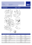
Ski, Engine, and Belly Pan
0727·100
Ref.
No.
Part No.
Qty.
1
2
3
4
5
6
7
8
9
10
11
12
13
14
15
16
17
18
0302·128
8011·070
0302·145
8040·366
8061·708
8002·130
8051·242
0302·112
0662·012
0300·200
0302·091
0302·056
0610·008
0302·057
0300·184
0302·061
3003·020
3010·016
1
4
1
4
15
8
4
1
1
1
1
1
AR
1
2
1
2
2
42
Description
Bumper
Bolt, Carriage
Belly Pan
Nut, Lock
Rivet
Screw, Cap
Washer, Lock
Plate, Engine
Engine, AA06A8
Strap
Cap, Gas
Tank, Gas
Hose, Fuel · 25'
Filter/Shut·Off
Pad
Bracket, Fuel Tank
Washer, Spring
Screw
Ref.
No.
Part No.
Qty.
Description
19
20
21
22
23
24
25
26
27
28
29
30
31
32
33
34
35
36
0300·133
8002·140
0123·425
0300·158
8040·426
0300·154
0300·187
8002·142
8050·247
8040·396
0300·124
0300·126
0300·189
0109·413
3003·023
8050·217
0123-498
8050·217
2
4
1
2
10
2
2
2
4
2
2
2
2
1
2
3
1
4
Spindle
Screw, Cap
Clamp
Sadd le
Nut, Lock
Spring
Cover, Saddle
Screw, Cap
Washer
Nut, Lock
Ski
Skag
Tip, Ski
Bushing
Washer
Washer
Clamp
Washer
..
•
--==~
Hood Assembly
0727·248
Ref.
No.
Part No.
Qty.
1
2
3
4
5
6
7
8
9
10
11
12
13
0300·176
0302·072
0609·005
0609·004
0609·006
0123·616
0123·614
0124·054
0302·066
0123·636
0123·149
0123·788
8041 ·126
1
1
1
1
1
4
4
6
1
2
4
4
2
Description
Hood
Bezel, Head light
Housing, Head Lamp
Bulb, Head Lamp
Socket, w/Rubber Cap
Screw, Adjusting
Spring, Adjusting
Snap & Cap
Harness, Wiring
Screw, Machine
Washer, Backing
Cable Ti e
Nut, Lock·Thin
Ref.
No.
14
15
16
17
18
19
20
21
22
23
24
Part No.
Qty.
0123·010
0123·549
021 2·549
0211·951
0302·150
0302·151
0302·152
0302·153
0211 ·950
0611·195
0606·097
0300·155
0300·185
8
8
1
1
1
1
1
1
2
2
1
2
2
Description
Nut, Expansion
Screw, Machine
Decal, "Arctic Cat"
Decal, Front Stripe
Decal, Side·Right
Decal, Side· Left
Decal, Rear Side·Right
Decal, Rear Side· Left
Decal, "Kitty Cat "
Tape, Reflective
Windshi eld
Hoo k, Latch
Latch, Rubber
43
Steering, Front Frame, and Console
0727·249
Ref.
No.
Part No.
Qty.
1
2
3
4
5
6
7
8
9
10
11
12
13
14
15
16
17
18
19
20
21
22
23
24
25
26
0302·119
8002·220
8050·272
8060·306
0123·534
0300·215
0300·210
0123·406
0302·093
0123·231
0302·085
0123·230
0302·147
8070·318
0302·045
0300·208
0109·822
0302·155
0116·065
0611·166
0211 ·849
0211 ·847
0302·092
8070·222
0302·165
0123·191
1
4
4
4
5
1
1
2
1
3
2
2
1
2
1
4
1
1
1
1
1
1
1
2
1
4
44
Description
Front End
Screw, Cap
Washer
Rivet
Nut, Snap·ln
Nut, Jam
Nut, Adjusting
Nut, Flange
Cable, Brake
Ring, Retaining
Lever
Pin
Grip·Left
Pin, Spring
Console
Screw, Self·Tapping
SWitch, Ignition
Decal, Dash
Key
Decal, "Caution"
Decal, "Choke"
Decal, "Throttle"
Cable, Throttle
Pin, Spring
Grip·Right
Nut, Jam
Ref.
No.
Part No.
Qty.
27
28
29
30
31
32
33
34
35
36
37
38
39
40
41
42
43
44
45
46
47
48
49
50
51
52
0302·084
01 23·788
8040·366
8002·070
0300·159
0300·140
0609·007
0706·034
0123·790
0302·082
8051 ·278
0123·851
0300·123
0302·162
8041 ·516
0302·080
8012·130
0611 ·022
0124·061
0300·211
0302·054
0302·088
8050·217
0123·397
8060·430
0109·960
1
5
4
4
1
1
1
1
1
1
4
1
4
2
4
1
2
1
2
1
1
4
6
1
1
2
Description
Handle, Steering
Cable Tie
Nut, Lock
Screw, Cap
Bracket, Steering
Clamp, Steering
Switch, Stop
Pad, Handlebar
Nut, Knurled
Ti e Rod
Washer, Lock
Washer, In1. Lock
Bali Joint
Crank, Spindle
Nut, Lock·Thin
Tie Rod, Front
Screw, Cap
Decal, Stop Switch
Washer, Pyramidal
Nut, Lock
Harness
Bushing
Washer
Clamp, Cable
Rivet
Cap, Handlebar
•
-
Seat, Tunnel, and Taillight
0727·250
Ref.
No.
Part No.
Qty.
Description
1
2
3
4
5
6
7
8
9
10
11
12
13
0302·143
8040·366
8002·070
8051·273
8002·250
0123·534
0116·074
8060·306
0117·860
0606·022
0300·169
8061·708
8061·710
1
4
4
4
4
1
8
41
2
1
1
5
4
Tunne l
Nut, Lock
Screw, Cap
W as her, Lock
Screw, Cap
Nut, Snap·ln
Snap
Rivet
Reflector
Plate, Rear
Bumper
Rivet
Rivet
Ref.
No.
Part No.
Qty.
14
15
16
17
18
19
20
21
22
23
24
25
0611·025
0300·173
8050·157
0302·131
0302·157
0116·378
0611-196
0623·012
0609·008
0609·011
8040·276
0115·588
1
1
4
1
1
8
2
1
1
1
2
AR
Description
Decal, Handl e
Ha ndle
Washer
Pad, Foam
Cover, Seat (in c. 19)
.Snap
Tape Reflective· 23" roll
Screw, Self·Tapp ing
Ta illamp Assembly (inc. 23)
• Bulb, Taillight
Nut, Lock
Tape
45
•
Drive, Undercarriage, and Track
0727·128
Ref.
No.
Part No.
1
2
3
4
5
6
7
8
9
10
11
12
13
14
15
16
17
18
19
20
21
22
23
46
0302·060
0300·208
0300·230
0300·229
0300·129
8051·272
8002·220
0300·153
8050·217
0300·151
0302·081
8050·242
0300·162
0302·086
0123·439
0123·765
8051·212
8004·037
0300·156
0300·167
0300·122
2204·001
8070·376
Qty.
1
2
1
2
1
6
6
1
1
1
1
2
1
1
22
1
1
1
1
1
1
1
1
Description
Guard, Chain
Screw, Self·Tapping
Pin, Brake
Pin, Hair
Bracket, Brake
Washer, Lock
Screw, Cap
Spring, Idler
Washer
Spacer, Brake
Tightener, Chain
Washer
Band, Brake
Clutch
Washer
Washer, Cup
Washer, Lock
Screw, Cap
Sprocket, Drive·42T
Track
Chain Ass'y. (inc. 22)
• Link, Connecting
Pin, Spring
Ref.
No.
Part No.
Qty.
24
25
26
27
28
29
30
31
32
33
34
35
36
37
38
39
40
41
42
43
44
45
0300·138
0302·118
0302·079
0300·179
0300·152
0300·181
8070·316
0300·144
8050·277
2081·000
0302·109
0302·104
0300·150
0302·101
0211·916
0300·178
8002·250
0300·180
0302·110
0302·111
0302·108
8051 ·273
4
2
1
2
2
1
4
1
2
2
1
4
8
6
1
2
2
1
2
1
1
2
Description
Flange
Bearing
Bracket, Brake Position
Sprocket, Track Drive
Spacer
Idler Wheel, Front
Pin, Spring
Driveshaft
Washer
Adjuster
Plate, Side·Left
Spacer
Spacer
Bogie Wheel
Decal, Warning
Sprocket, Idler
Screw, Cap
Idler Wheel, Rear
Axle
Axle, Rear
Plate, Side·Right
Washer, Lock
•
•
Crankcase and Cylinder
0727-251
Ref_
No_
Part No_
Qty_
1
2
3
4
5
6
7
8
9
10
11
3002-469
3002-470
3002-454
3003-020
3002-616
3002-472
3002-451
3003-185
3002-012
3003-259
3002-617
1
1
4
6
1
1
4
1
2
9
1
Description
Head, Cylinder
Gasket, Head
Nut
Washer, Lock
Cyli nder
Gasket, Cyl inder
Bolt, Stud
Crankcase Ass'y. (inc. 9 & 10)
.Pin, Dowel
.Screw
Case, Gear
Ref.
No.
Part No.
Qty.
12
13
14
15
16
17
18
19
20
21
3002-475
3002-445
3002-012
3002-519
3003-260
3002-456
3002-460
3003-188
3010-016
3003-023
1
1
2
1
2
2
1
1
2
2
Description
Gasket, Gear Case
Screw
Pin, Dowel
Plug, Breather
Plug, Oil Level
Gasket, Oil Level
Plug, Oil Fill er
Gasket, Oil Filler
Screw
Washer
47
Piston and Crankshaft
0720·071
Ref.
No.
Part No.
1
2
3
4
5
6
7
8
3002·476
3002·477
3002·478
3003·186
3010·264
3002·479
3010·318
3002·480
aty.
1
1
1
1
2
1
1
1
Description
Piston
Ring Assembly
Pin
Bearing
Circlip
Crankshaft Ass'y. (inc. 7-11)
• Rod, Connecting
.Pin
Ref.
No.
Part No.
aty.
9
10
11
12
13
14
15
16
~QQ~·;m~
3002·481
3002-482
3003·320
3003·261
3002-462
3002-463
3010-070
1
1
1
1
1
1
1
2
Description
• Bearing
• Crankshaft-Right
• Crankshaft·Left
Bearing·Right
Bearing-Left
Oil Seal·Right
Oil Seal·Left
Key
.48
18
Muffler, Cowling, and Silencer
0727·253
Ref.
No.
Part No.
Qty.
1
2
3
4
5
6
7
8
9
10
11
12
13
3003·266
3002·488
3002·436
3003·264
3003·190
3002·491
3002·443
3003·175
3003·023
3002·461
0212·283
3002·492
3002·348
1
1
2
4
10
1
4
1
6
1
1
1
2
Description
Muffler
Gasket
Bolt, Stud
Nut
Washer, Lock
Cover, Cooling Fan
Screw
Cap, Spark Plug
Washer
Plug, Magn eto Inspection
Emblem
Cowling
Screw
Ref.
No.
Part No.
Qty.
14
15
16
17
18
19
20
21
22
23
24
25
3003·206
0217·027
3002·483
3002·484
3002·439
3002·485
3002·689
3002·486
3002·487
3002·458
3003·165
3003·265
2
1
2
1
2
1
2
1
1
2
2
1
Description
Washer, Lock
Spark Plug, BR·6HS
Gasket
Insulator
Bolt, Stud
Rod, Choke Valve
Nut
Silencer Ass'y. (inc. 25)
Gasket
Spacer
Bolt, Stud
Grommet
49
' / - -- 7
18
Governor
0727·132
Ref.
No.
Part No.
aty.
1
2
3
4
5
6
7
8
9
10
11
12
13
14
15
3002·619
3002·509
3002·510
3002·511
3002·684
3002·462
3002·512
3002·615
3003·267
3003·190
3003·020
3002·690
3002·452
3003·321
3002·620
1
1
1
1
2
1
1
1
2
2
2
1
1
1
1
50
Description
Centrifugal
Shifter
Shaft, Throttle
Plate, Throttle
Screw
Seal, Oil
Lever, Throttle
Spring
Bolt
Washer, Lock
Washer
Nut
Bolt
Bearing·Left
Lever, Throttle
Return
Return
Control
Cable
Ref.
No.
Part No.
aty.
16
17
18
19
20
21
22
23
24
25
26
27
28
29
30
3002·702
3002·459
3003·320
3002·518
3002-455
3002-468
3002-621
3003·268
3002-689
3002-515
3002-466
3002-516
3002-736
3002-517
3002-912
1
1
1
1
1
1
1
1
1
1
1
1
1
1
1
Description
Bolt
Spacer
Bearing·Right
Shaft, Primary Driven
Washer
Spring
Bracket, Throttle Cable
Bolt, Adjuster
Nut, Adjuster
Rod, Carburetor
Spring, Carburetor Rod
Gear, Primary Drive
Nut
Gear, Primary Driven
Washer, Lock
l
Carburetor
0720·072
Ref.
No.
Part No.
Qty.
1
2
3
4
5
6
7
8
9
3002·618
6505·285
3003·189
6505·292
6505·287
6505-288
6505·293
6505·244
6505·297
1
1
1
1
1
1
1
1
1
Description
Carburetor Ass'y. (inc. 2·17)
.Tube
.Main Jet
.Ring
.Float
.Pin, Float
• Needle Valve Ass'y.
• Gasket
• Pilot Jet No. 35
Ref.
No.
Part No.
Qty.
10
11
12
13
14
15
16
17
6505-294
6505-289
3003-262
6505-013
6505·284
6505·286
3003·263
6505·291
1
1
1
1
1
1
1
1
Description
.Screw, Throttle Adjusting
.Spring
.Bolt
.Washer
• Nozzle
• Gasket, Float Chamber
• Screw, Pilot Adjusting
.Spring
51
9
16)){ '15
18
Magneto
0727·133
Ref.
No.
Part No.
Qty.
1
2
3
4
5
6
7
8
9
3003·150
3003·146
3003·147
3002·711
3003·097
3003·270
3003·145
3002·453
3002·490
1
1
1
4
6
1
1
3
1
52
Description
Stator (inc. 2·6)
• Coil, Lighting
.Coil, Primary
.Screw
• Washer, Lock
.Screw
Rotor
Screw
Fan
Ref.
No.
Part No.
Qty.
Description
10
11
12
13
14
15
16
17
18
3002·446
3002·664
3002·450
3003·053
3002·464
3003·191
3002·349
3003·020
3002·465
4
1
1
1
1
1
2
2
1
Screw
Nut
Washer
Washer, Lock
Clamp
Coil Ass'y.
Screw
Washer, Lock
Clamp
17
Recoil Starter
0720·076
Ref.
No.
Part No.
aty.
1
2
3
4
5
6
7
8
9
10
3002·493
3002·494
3002·495
3002·496
3002·497
3002·498
3002·499
3003·317
3002·501
3002·502
1
1
1
2
1
1
1
1
1
2
Description
Recoil Starter Ass'y. (inc. 2·12)
.Case, Recoil
• Reel, Recoil
.Pawl
.Spring, Recoil
• Plate, Drive
.Spring
.Cover, Spring
.Spring, Return
.Washer
Ref.
No.
11
12
13
14
15
16
17
18
19
Part No.
aty.
3003·318
3002·504
1
1
1
3
3
1
1
3
3
3002~505
3010·016
3003-020
3002·506
3002·507
3002·279
3003·206
Description
.E·Ring
.Grip Ass'y. (inc. 13)
•• Grip
Screw
Washer, Lock
Pulley, Starter
Spacer
Screw
Washer, Lock
53
Related Items
Description
Black Metal Paint
Headlight Bulb
Taillight Bulb
Arctco 50:1 Oil- 55 U.S. gal.
Arctc050:1 Oil-1 qt
Arctco 20:1 Oil- 1 qt
Arctco 20:1 Oil- 55 U.S. gal.
Arctco Engine Preserver
Wheel Kit
Kitty Cat Machine Cover
Kitty Cat Machine Cover
Operator's Manual
Safety Handbook
Tool Kit
RTV 732 Sealant - (3 oz tube)
Parts/Service Manual
Machine Cover
Arctic Cat 50:1 Oil- 55 U.S. gal.
Arctic Cat 50:1 Oil- 16 oz.
Arctic Cat 20:1 Oil - 1 qt.
Part Number
0652-004
0609-004
0609-011
0636-026
0636-027
0636-028
0636-081
0636-177
0134-707
0636-0350636-109 /'
2254-344
2254-347
0155-619
0134-971
2254-350
0352-009
0352-138
0355-018
0134-124
NOTE: For a complete li st of related item s, refer
to th e Accesso ri es and Options Manual.
54