1
User Manual
AIMB-267 KIOSK
Intel® LGA775 Core™ 2 Quad/
Duo Mini ITX Motherboard with
DDR3/ 8 COM/ Dual LAN/
VGA+LVDS/ PCIe x 1
Safety Information
Electrical safety
To prevent electrical shock hazard, disconnect the power cable from the electrical outlet before relocating the system.
When adding or removing devices to or from the system, ensure that the power
cables for the devices are unplugged before the signal cables are connected. If
possible, disconnect all power cables from the existing system before you add a
device.
Before connecting or removing signal cables from the motherboard, ensure that
all power cables are unplugged.
Seek professional assistance before using an adapter or extension cord. These
devices could interrupt the grounding circuit.
Make sure that your power supply is set to the correct voltage in your area. If
you are not sure about the voltage of the electrical outlet you are using, contact
your local power company.
If the power supply is broken, do not try to fix it by yourself. Contact a qualified
service technician or your retailer.
Operation safety
Before installing the motherboard and adding devices on it, carefully read all the
manuals that came with the package.
Before using the product, make sure all cables are correctly connected and the
power cables are not damaged. If you detect any damage, contact your dealer
immediately.
To avoid short circuits, keep paper clips, screws, and staples away from connectors, slots, sockets and circuitry.
Avoid dust, humidity, and temperature extremes. Do not place the product in
any area where it may become wet.
Place the product on a stable surface.
If you encounter technical problems with the product, contact a qualified service
technician or your retailer.
AIMB-267 KIOSK User Manual
Part No. 2006026710
Edition 1
Printed in Taiwan
March 2012
ii
A Message to the Customer
Advantech Customer Services
Each and every Advantech product is built to the most exacting specifications to
ensure reliable performance in the harsh and demanding conditions typical of industrial environments. Whether your new Advantech equipment is destined for the laboratory or the factory floor, you can be assured that your product will provide the
reliability and ease of operation for which the name Advantech has come to be
known.
Your satisfaction is our primary concern. Here is a guide to Advantech’s customer
services. To ensure you get the full benefit of our services, please follow the instructions below carefully.
Technical Support
We want you to get the maximum performance from your products. So if you run into
technical difficulties, we are here to help. For the most frequently asked questions,
you can easily find answers in your product documentation. These answers are normally a lot more detailed than the ones we can give over the phone.
So please consult this manual first. If you still cannot find the answer, gather all the
information or questions that apply to your problem, and with the product close at
hand, call your dealer. Our dealers are well trained and ready to give you the support
you need to get the most from your Advantech products. In fact, most problems
reported are minor and are able to be easily solved over the phone.
In addition, free technical support is available from Advantech engineers every business day. We are always ready to give advice on application requirements or specific
information on the installation and operation of any of our products.
Declaration of Conformity
FCC
This device complies with the requirements in part 15 of the FCC rules:
Operation is subject to the following two conditions:
This device may not cause harmful interference
This device must accept any interference received, including interference that
may cause undesired operation.
This equipment has been tested and found to comply with the limits for a Class A digital device, pursuant to Part 15 of the FCC Rules. These limits are designed to provide reasonable protection against harmful interference when the equipment is
operated in a commercial environment. This equipment generates, uses, and can
radiate radio frequency energy and, if not installed and used in accordance with the
instruction manual, may cause harmful interference to radio communications. Operation of this device in a residential area is likely to cause harmful interference in which
case the user will be required to correct the interference at his/her own expense. The
user is advised that any equipment changes or modifications not expressly approved
by the party responsible for compliance would void the compliance to FCC regulations and therefore, the user's authority to operate the equipment.
iii
AIMB-267 KIOSK User Manual
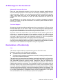
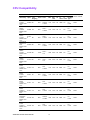
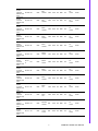
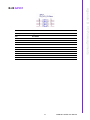
CPU Compatibility
Test Item
CPU Family sSpec.
Description
Core
Power Vcore
Stepping
FSB
Mfg.
Tech
HT
L2
L3
Package Result Remark
cache cache Type
Quad Q9650
3.0GHz
SLB8W E0
EM64T Quad
Core
95W
0.8500V 1333
1.3625V
45nm NA 12MB
NA
FCLGA6
PASS
CoreQuad
Q9400
SLB6B R0
2.66GHz
EM64T Quad
Core
95W
0.85V 1.3625V
1333
45nm NA na
NA
FCLGA6
PASS
Core2Quad
Q9300
SLAW
2.5GHz
E
EM64T Quad
Core
M1
95W
0.85V 1.3625V
1333
45nm NA 6MB
NA
FCLGA6
PASS
Core2 Quad
Q8200 2.33
SLB5M M1
GHz
EM64T Quad
Core
95W
0.85V 1.3625V
1333
45nm NA 4MB
NA
FCLGA6
PASS
Core2 Quad
Q6600
SL9UM B3
2.4GHz
EM64T Quad
Core
105W
0.85V 1.5V
1066
65nm NA 8MB
NA
FCLGA6
PASS
Core2 Quad
Q6600
SLACR B3
2.4GHz
EM64T Quad
Core
95W
0.85V 1.5V
1066
65nm NA 8MB
NA
FCLGA6
PASS
Core2 Duo
E8500
SLAPK C0
3.16GHz
EM63T Dual
Core
65W
0.851.3625V
1333
45nm NA 6MB
NA
FCLGA6
PASS
Core2 Duo
E8400
SLB9J E0
3.0GHz
EM64T Dual
Core
65W
0.85V1.3625V
1333
45nm NA 6MB
NA
FCLGA6
PASS
Core2 Duo
E8400
SLAPL C0
3.0GHz
EM64T Dual
Core
65W
0.851.3625V
1333
45nm NA 6MB
NA
FCLGA6
PASS
Core2 Duo
E8200
SLAPP C0
2.66GHz
EM64T Dual
Core
65W
0.851.3625V
1333
45nm NA 6MB
NA
FCLGA6
PASS
Core2
DuoE7500
SLGTE R0
2.93GHz
EM64T Dual
Core
65W
0.8500V1066
V1.3625
45nm NA 3MB
NA
FCLGA6
PASS
Core2 Duo
E7400
SL6W3 R0
2.80GHz
EM64T Dual
Core
65W
0.851.3625V
45nm NA 3MB
NA
FCLGA6
PASS
AIMB-267 KIOSK User Manual
1066
iv
Core2 Duo
E7300
SLAPB M0
2.66GHz
EM64T Dual
Core
65W
0.851.3625V
1066
45nm NA 3MB
NA
FCLGA6
PASS
Core2 Duo
E7200
SLAVN M0
2.53GHz
EM64T Dual
Core
65W
0.851.3625V
1066
45nm NA 3MB
NA
FCLGA6
PASS
Core2 Duo
E6700
SL9ZF B2
2.66GHz
EM64T Dual
Core
65W
0.8501.3525V
1066
65nm NA 4MB
NA
FCLGA6
PASS
Core2 Duo
E6700
SL9S7 B2
2.66GHz
EM64T Dual
Core
65W
0.8501.3525V
1066
65nm NA 4MB
NA
FCLGA6
PASS
Core2 Duo
E6600
SL9S8 B2
2.40GHz
EM64T Dual
Core
65W
0.8501.3525V
1066
65nm NA 4MB
NA
FCLGA6
PASS
Core2 Duo
E6550
SLA9X G0
2.33GHz
EM64T Dual
Core
65W
0.962V1.350V
1333
65nm NA 4MB
NA
FCLGA6
PASS
Core2 Duo
E6500
SLGU
2.93GHz
H
EM64T Dual
Core
R0
65W
0.962V1.350V
1066
45nm NA 2MB
NA
FCLGA6
PASS
Core2 Duo
E6400
SL9S9 B2
2.13GHz
EM64T Dual
Core
65W
0.8501.3525V
1066
65nm NA 2MB
NA
FCLGA6
PASS
Core2 Duo
E6300
SL9SA B2
1.86GHz
EM64T Dual
Core
65W
0.8501.3525V
1066
65nm NA 2MB
NA
FCLGA6
PASS
Core2 Duo
E6420
SLA4T B2
2.13GHz
EM64T Dual
Core
65W
0.8501.5V
1066
65nm NA 4MB
NA
FCLGA6
PASS
Core2 Duo
E6320
SLA4U B2
1.86GHz
EM64T Dual
Core
65W
0.8501.5V
1066
65nm NA 4MB
NA
FCLGA6
PASS
Core2 Duo
E5300
SLB9U R0
2.6GHz
EM64T Dual
Core
65W
0.85V®C
800
1.3625V
45nm NA 2MB
NA
FCLGA6
PASS
Core2 Duo
E4700
SLALT G0
2.6GHz
EM64T Dual
Core
65W
1.162V1.312V
65nm NA 2MB
NA
FCLGA6
PASS
800
v
AIMB-267 KIOSK User Manual
Core2 Duo
E4500
SLA95 M0
2.2GHz
EM64T Dual
Core
65W
0.8501.5V
800
65nm NA 2MB
NA
FCLGA6
PASS
Core2 Duo
E4300
SL9TB L2
1.8GHz
EM64T Dual
Core
65W
0.85V®C
800
1.5V
65nm NA 2MB
NA
FCLGA6
PASS
Pentium
Dual-Core
1.8GHz
E2160
SLA8Z M0
65W
0.85V1.5V
800
65nm NA 1MB
NA
FCLGA6
PASS
Pentium
Dual-Core
1.8GHz
E2160
SLA3H L2
65W
0.85V1.5V
800
65nm NA 1MB
NA
FCLGA6
PASS
Pentium
Dual-Core
1.6GHz
E2140
SLA3J L2
65W
1.162V1.312V
800
65nm NA 1MB
NA
FCLGA6
PASS
Celeron
E1500
2.2GHz
EM64T
SLAQZ M0
65W
0.9621.275V
800
65nm NA 512KB NA
FCLGA6
PASS
Celeron
E1200
1.6GHz
EM64T
SLAQ
W
1.162V
1.162V1.312V
1.312V
800
65nm NA 512KB NA
FCLGA6
PASS
Celeron 440
2GHz
SL9XL A1
35W
1.01.3375V
800
65nm NA 512KB NA
FCLGA6
PASS
Celeron 430
1.8GHz
SL9XN A1
35W
1.01.3375V
800
65nm NA 512KB NA
FCLGA6
PASS
Celeron 420
1.6GHz
SL9XP A1
35W
1.01.3375V
800
65nm NA 512KB NA
FCLGA6
PASS
M0
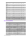
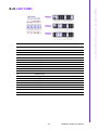
Memory Compatibility
Brand
Size
Speed Type
ECC Vendor PN
Memory
Apacer
4GB
DDR3
DDR3
1066
N
78.B1GDJ.AF1
HYNIX H5TQ2G83BFRNA
H9C
ATP
4GB
DDR3
DDR3
1066
N
SAMSUNG 940
AQ12M64B8BKF8S K4B2G0846B-HCF8
(256x8)
NA
Transcend 2GB
DDR3
DDR3
1333
N
TS256MLK64V3N
96D3-2G1333NNPASS
TR1
Transcend 2GB
DDR3
DDR3
1333
N
TS256MLK64V3U
Transcend 4GB
DDR3
DDR3
1333
N
TS512MLK64V3U
Apacer
2GB
DDR3
DDR3
1333
N
78.A1GDE.4200C
ELPIDA J2108BCSEDJ-F
Apacer
2GB
DDR3
DDR3
1333
N
78.A1GDE.AF00C
Hynix
96D3-2G1333NNPASS
H5TQ2G838FR(256x8) AP1
Apacer
4GB
DDR3
DDR3
1333
N
78.B1GDE.AF1
HYNIX H5TQ2G83BFR- 96D3-4G1333NNPASS
H9C
AP
Kingston
4GB
DDR3
DDR3
1333
N
KVR1333D3N9/4G
KINGSTON
D2568JENCPGD9U(51 NA
2x64)
ATP
4GB
DDR3
DDR3
1333
N
SAMSUNG 949
AQ12M64B8BKH9S K4B2G0846B-HCH9
(256x8)
AIMB-267 KIOSK User Manual
vi
SEC K4B1G0846GBCH9
Advantech PN
Result
PASS
PASS
96D3-2G1333NNPASS
TR4
96D3-4G1333NNPASS
TR
96D3-2G1333NNPASS
AP2
NA
PASS
PASS
Transcend 2GB
DDR3
DDR3
1066
N
TS256MLK64V1U
SEC K4B1G0846GBCH9
96D3-2G1066NNPASS
TR
Apacer
2GB
DDR3
DDR3
1066
N
78.A1GC3.421
ELPIDA J1108BDBGDJ-F (128x8)
96D3-2G1066NNPASS
AP
Kingston
2GB
DDR3
DDR3
1333
N
KVR1333D3S8N9/
2G
ELPIDA J2108BCSEDJ-F(128x8)
NA
PASS
DSL
2GB
DDR3
DDR3
1600
N
D3US56081XH12A
A
SEC 113 HCK0
K4B2G0846C 256x8
NA
PASS
DSL
4GB
DDR3
DDR3
1600
N
D3US56082XH12A
A
SEC 113 HCK0
K4B2G0846C 256x8
NA
PASS
Transcend 4GB
DDR3
DDR3
1600
N
TS512MLK64V6N
MICRON IUM22 D9PFJ NA
PASS
Transcend 2GB
DDR3
DDR3
1600
N
TS256MLK64V6N
MICRON IRM72 D9PFJ NA
PASS
Transcend 1GB
DDR3
DDR3
1066
N
TS128MLK64V1U
SEC K4B1G0846GBCH9
96D3-1G1066NNPASS
TR
Apacer
1GB
DDR3
DDR3
1066
N
78.01GC3.420
ELPIDA J1108BDBGDJ-F (128x8)
96D3-1G1066NNPASS
AP
Transcend 1GB
DDR3
DDR3
1333
N
TS128MLK64V3U
ELPIDA
EDJ1108BFBG-DJ-F
96D3-1G1333NNPASS
TR
Apacer
DDR3
DDR3
1333
N
78.01GC6.AF0
H5TQ1G83DFR-H9C
96D3-1G1333NN- PASS
AP1
PASS
1GB
H5TQ1G83TFR-H9C
Ordering Information
Display
LAN
COM
Chipset
AIMB-267VG-KSA1E
VGA
1
8
G41+ICH7
AIMB-267G2-KSA1E
VGA/ LVDS
2
8
G41+ICH7
Product Warranty (2 years)
Advantech warrants to you, the original purchaser, that each of its products will be
free from defects in materials and workmanship for two years from the date of purchase.
This warranty does not apply to any products which have been repaired or altered by
persons other than repair personnel authorized by Advantech, or which have been
subject to misuse, abuse, accident or improper installation. Advantech assumes no
liability under the terms of this warranty as a consequence of such events.
Because of Advantech’s high quality-control standards and rigorous testing, most of
our customers never need to use our repair service. If an Advantech product is defective, it will be repaired or replaced at no charge during the warranty period. For outof-warranty repairs, you will be billed according to the cost of replacement materials,
service time and freight. Please consult your dealer for more details.
If you think you have a defective product, follow these steps:
1. Collect all the information about the problem encountered. (For example, CPU
speed, Advantech products used, other hardware and software used, etc.) Note
anything abnormal and list any onscreen messages you get when the problem
occurs.
2. Call your dealer and describe the problem. Please have your manual, product,
and any helpful information readily available.
3. If your product is diagnosed as defective, obtain an RMA (return merchandise
authorization) number from your dealer. This allows us to process your return
more quickly.
vii
AIMB-267 KIOSK User Manual
4.
5.
Carefully pack the defective product, a fully-completed Repair and Replacement
Order Card and a photocopy proof of purchase date (such as your sales receipt)
in a shippable container. A product returned without proof of the purchase date
is not eligible for warranty service.
Write the RMA number visibly on the outside of the package and ship it prepaid
to your dealer.
Initial Inspection
Before you begin installing your motherboard, please make sure that the following
materials have been shipped:
LGA 775 CoreTM 2 Quad Pentium dual-core/Celeron® Processor-based Mini
ITX with DDR3/Dual LAN/PCIe x 1
1 x AIMB-267 KIOSK startup manual
1 x CD with driver utility and manual
2 x Serial ATA HDD data cable
2 x COM port cable kit
1 x I/O port bracket
1 x warranty card
If any of these items are missing or damaged, contact your distributor or sales representative immediately. We have carefully inspected the AIMB-267 KIOSK mechanically and electrically before shipment. It should be free of marks and scratches and in
perfect working order upon receipt. As you unpack the AIMB-267 KIOSK, check it for
signs of shipping damage. (For example, damaged box, scratches, dents, etc.) If it is
damaged or it fails to meet the specifications, notify our service department or your
local sales representative immediately. Also notify the carrier. Retain the shipping
carton and packing material for inspection by the carrier. After inspection, we will
make arrangements to repair or replace the unit.
AIMB-267 KIOSK User Manual
viii
Contents
Chapter
1
General Information ............................1
1.1
1.2
1.3
1.9
1.10
1.11
1.12
Introduction ............................................................................................... 2
Features .................................................................................................... 2
Specifications ............................................................................................ 2
1.3.1 System .......................................................................................... 2
1.3.2 Memory ......................................................................................... 2
1.3.3 Input/Output .................................................................................. 2
1.3.4 Graphics........................................................................................ 3
1.3.5 Ethernet LAN ................................................................................ 3
1.3.6 Industrial Features ........................................................................ 3
1.3.7 Mechanical and Environmental Specifications.............................. 3
Jumpers and Connectors .......................................................................... 4
Table 1.1: Jumpers...................................................................... 4
Table 1.2: Connectors ................................................................. 4
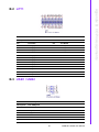
Board layout: Jumper and Connector Locations ....................................... 5
Figure 1.1 Jumper and Connector Location ................................ 5
Figure 1.2 I/O Connectors ........................................................... 5
AIMB-267 KIOSK Block Diagram.............................................................. 6
Figure 1.3 AIMB-267 KIOSK Block Diagram ............................... 6
Safety Precautions .................................................................................... 7
Jumper Settings ........................................................................................ 8
1.8.1 How to set jumpers ....................................................................... 8
1.8.2 CMOS clear (CMOS1) .................................................................. 8
Table 1.3: CMOS1....................................................................... 8
1.8.3 Chassis instruction connector (JCASE1) ...................................... 8
1.8.4 ATX/AT mode selector (PSON1) .................................................. 8
Table 1.4: ATX/AT mode selector (PSON1)................................ 8
1.8.5 COM3 RS 232/422/485 mode selector (JSETCOM3) .................. 9
Table 1.5: COM3 RS 232/422/485 mode selector (JSETCOM3) 9
1.8.6 JLVDS1/JLVDS2 Voltage Selector for LVDS1 Connector ............ 9
Table 1.6: Voltage selector :........................................................ 9
System Memory ........................................................................................ 9
Memory Installation Procedures.............................................................. 10
Cache Memory........................................................................................ 10
Processor Installation.............................................................................. 10
2
Connecting Peripherals ....................11
2.1
2.2
Introduction ............................................................................................. 12
Parallel Port (LPT1)................................................................................. 12
Table 2.1: Parallel Port (LPT1) .................................................. 12
USB Ports (LAN1_USB01/LAN2_USB23/USB1/USB2) ......................... 13
Table 2.2: LAN LED Indicator.................................................... 13
VGA Connector (VGA1) .......................................................................... 14
Serial Ports (COM1~COM8) ................................................................... 15
PS/2 Keyboard and Mouse Connector (KBMS1) .................................... 16
CPU Fan Connector (CPU_FAN1).......................................................... 17
System FAN Connector (SYS_FAN1/2).................................................. 18
Front Panel Connectors (JFP1+JFP2) .................................................... 19
Table 2.3: Power Switch/RESET/HDD LED/SM Bus/Internal
Buzzer/External Speaker.......................................... 19
JOBS1+JWDT1+JFP3 Connector........................................................... 20
Table 2.4: JOBS1+JWDT1+JFP3 Connector ............................ 20
Line In/Line Out/Mic In Connector (AUDIO1).......................................... 21
1.4
1.5
1.6
1.7
1.8
Chapter
2.3
2.4
2.5
2.6
2.7
2.8
2.9
2.10
2.11
ix
AIMB-267 KIOSK User Manual
2.12
2.13
2.14
2.15
2.16
2.17
2.18
Serial ATA Interface (SATA1+SATA2).................................................... 21
ATX Power Connector (ATX12V1+ATXPWR1) ..................................... 22
SPI BIOS Socket (SPI1) ......................................................................... 23
Front Panel Audio Connector (FPAUD1) ................................................ 23
GPIO Pin Header (GPIO1)...................................................................... 24
LVDS Connector (LVDS1) ...................................................................... 24
Inverter Connector for LVDS1 (INV1) ..................................................... 25
3
BIOS Operation ................................. 27
3.1
3.2
3.7
Main Menu .............................................................................................. 28
Advanced BIOS Setting .......................................................................... 29
3.2.1 Configure Advanced CPU Setting .............................................. 29
3.2.2 IDE Configuration ....................................................................... 30
3.2.3 Super I/O configuration............................................................... 31
3.2.4 Hardware Health Configuration .................................................. 32
3.2.5 ACPI Setting ............................................................................... 33
3.2.6 APM Configuration...................................................................... 35
3.2.7 MPS Configuration...................................................................... 36
3.2.8 Smbios Configuration ................................................................. 36
3.2.9 USB Configuration ...................................................................... 37
Advanced PCI/PnP Setting ..................................................................... 38
Boot Setting ............................................................................................ 40
Security Setting....................................................................................... 41
Advanced Chipset Setting....................................................................... 42
3.6.1 North Bridge Chipset Configuration ............................................ 42
3.6.2 South Bridge Chipset Configuration ........................................... 44
Exit Options............................................................................................. 45
4
Chipset Software Installation Utility 47
4.1
4.2
4.3
Before you begin..................................................................................... 48
Introduction ............................................................................................. 48
Windows XP/Windows 7 Driver Setup .................................................... 49
5
VGA Setup ......................................... 51
5.1
5.2
Introduction ............................................................................................. 52
Windows XP/7......................................................................................... 52
6
LAN Configuration ............................ 55
6.1
6.2
6.3
6.4
Introduction ............................................................................................. 56
Features.................................................................................................. 56
Installation............................................................................................... 56
Windows XP/ Windows 7 Setup (Realtek RTL8111E)............................ 56
Appendix A
Programming the Watchdog Timer . 59
A.1
Programming the Watchdog Timer ......................................................... 60
A.1.1 Watchdog timer overview ........................................................... 60
A.1.2 Programming the Watchdog Timer............................................. 60
Table A.1: Watchdog Timer Registers....................................... 62
A.1.3 Example Program ....................................................................... 63
Chapter
3.3
3.4
3.5
3.6
Chapter
Chapter
Chapter
AIMB-267 KIOSK User Manual
x
Appendix B
I/O Pin Assignments..........................65
B.1
AIMB-267 KIOSK Jumper Setting & Connector List ............................... 66
Figure B.1 Top View................................................................... 66
Figure B.2 Bottom View ............................................................. 66
LPT1........................................................................................................ 67
USB1 / USB2 .......................................................................................... 67
USB/LAN................................................................................................. 68
VGA1....................................................................................................... 68
COM1 ~ 3................................................................................................ 69
COM4...................................................................................................... 69
COM5678................................................................................................ 70
KBMS1 .................................................................................................... 71
CPUFAN1 ............................................................................................... 71
SYSFAN1~2............................................................................................ 72
JFP1+JFP2 ............................................................................................. 72
JOBS1+JWDT1+JFP3 ............................................................................ 73
Audio1 ..................................................................................................... 73
SATA1~2................................................................................................. 74
ATX12V1................................................................................................. 74
ATXPWR1............................................................................................... 75
SPI1 ........................................................................................................ 76
FPAUD1 .................................................................................................. 76
GPIO1 ..................................................................................................... 77
LVDS1..................................................................................................... 78
JSETCOM3 ............................................................................................. 79
INV1 ........................................................................................................ 80
CMOS1 ................................................................................................... 80
PSON1 .................................................................................................... 81
JLVDS1 / JLVDS2................................................................................... 81
JCASE1................................................................................................... 82
BAT1 ....................................................................................................... 82
DMA Channel Assignments .................................................................... 82
Interrupt Assignments ............................................................................. 83
1st MB Memory Map ............................................................................... 83
B.2
B.3
B.4
B.5
B.6
B.7
B.8
B.9
B.10
B.11
B.12
B.13
B.14
B.15
B.16
B.17
B.18
B.19
B.20
B.21
B.22
B.23
B.24
B.25
B.26
B.27
B.28
B.29
B.30
B.31
xi
AIMB-267 KIOSK User Manual
AIMB-267 KIOSK User Manual
xii
Chapter
1
1
General Information
1.1 Introduction
The AIMB-267 KIOSK is designed with the Intel G41 and the ICH7 for industrial applications that require both performance computing and enhanced power management
capabilities. The motherboard supports Intel LGA 775 Core 2 Quad up to 2.66 GHz/
Core 2 Duo up to 3.16 GHz/Pentium Dual-Core up to 2.93 GHz/Celeron up to 1.6
GHz with 800/1066/1333 MHz front side bus and DDR3 800/1066 MHz up to 4 GB.
The AIMB-267 KIOSK offers cost-saving integrated graphics, built on the Intel G41
chipset and features the unique Intel Extreme Graphics architecture that maximizes
VGA performance and shares system memory up to 352 MB.
Advantech AIMB-267 KIOSK is designed with an Intel G41 chipset and supports Intel
Core 2 Quad/Duo processor up to FSB 1333 MHz. A rich I/O connectivity of 8 serial
ports, 8 USB 2.0, dual GbE LAN and 2 SATA ports.
1.2 Features
Cost effective G41 chipset: supports 800/1066/1333 Front side bus
Rich I/O connectivity: 8 serial ports, 8 USB 2.0, dual GbE LAN
Standard Mini ITX form factor with industrial feature: The AIMB-267 KIOSK
is a fully-featured Mini ITX motherboard with balanced expandability and the
performance
Wide selection of storage devices: SATA HDD, customers benefit from the
flexibility of using the most suitable storage device
Optimized integrated graphic solution: With Intel Graphics Media Accelerator
X4500, supports versatile display options and 32-bit 3D graphics engine
1.3 Specifications
1.3.1 System
CPU: LGA775 Core 2 Quad up to 2.66 GHz/Core 2 Duo up to 3.16 GHz/Pentium Dual-Core up to 2.93 GHz/Celeron up to 1.6 GHz with 800/1066/1333 MHz
front side bus
BIOS: AMI SPI 16 Mbit BIOS
System chipset: Intel G41 with ICH7
SATA hard disk drive interface: Two on-board SATA connectors with data
transmission rate up to 300 MB
1.3.2 Memory
RAM: Up to 4 GB in 1 slot 240-pin DIMM socket. Supports single channel DDR3
800/1066 MHz SDRAM
1.3.3 Input/Output
PCIe bus: 1PCIe x1 slot
Enhanced parallel port: Configured to LPT1 with 25 pin box header. Supports
EPP/SPP/ECP
Serial ports: Eight serial ports, one of RS-232/422/485 and seven of RS-232
serial ports
Keyboard and PS/2 mouse connector: Two 6-pin mini-DIN connectors are
located on the mounting bracket for easy connection to a PS/2 keyboard and
mouse
AIMB-267 KIOSK User Manual
2
USB port: Supports up to eight USB 2.0 ports with transmission rates up to 480
Mbps, (4 on board pin header and 4 external ports)
1.3.4 Graphics
Controller: Chipset integrated VGA controller
Display memory: Dynamically shared system memory up to 224 MB
CRT: Up to 2048 x 1536 resolution, 400 MHz RAMDAC
Supporting single/dual 10/100/1000Base-T Ethernet port (s) via PCIe x1 bus
which provides 500 MB/s data transmission rate
Controller: LAN: Realtek RTL8111E
1.3.6 Industrial Features
Watchdog timer: Can generate a system reset. The watchdog timer is programmable, with each unit equal to one second or one minute (255 levels).
1.3.7 Mechanical and Environmental Specifications
Operating temperature: 0 ~ 60° C (32 ~ 140° F), depends on CPU speed and
cooler solution
Storage temperature: -40 ~ 85° C (-40 ~ 185° F)
Humidity: 5 ~ 95% non-condensing.
Power supply voltage: +3.3 V, +5 V, +12 V, -12 V, 5 Vsb.
Power consumption:
+5 V @ 1.91 A, +3.3 V @ 0.35 A, +12 V @ 1.29 A, 5 VSB @ 0.18 A, -12 V @
0.06 A Measure the maximum current value which system under maximum
load (CPU: Top speed, RAM & Graphic= full loading).
Board size: 170 mm x 170 mm (6.69" x 6.69")
Board weight: 0.365 kg
3
AIMB-267 KIOSK User Manual
General Information
1.3.5 Ethernet LAN
Chapter 1
1.4 Jumpers and Connectors
Connectors on the AIMB-267 KIOSK motherboard link it to external devices such as
hard disk drives and a keyboard. In addition, the board has a number of jumpers
used to configure the system for your application.
The tables below list the function of each of the board jumpers and connectors. Later
sections in this chapter give instructions on setting jumpers. Chapter 2 gives instructions for connecting external devices to your motherboard.
Table 1.1: Jumpers
Label
Function
CMOS1
CMOS clear (Default 1-2)
JCASE1
JCASE OPEN connector
PSON1
AT (1-2)/ATX (2-3) (Default 2-3)
JSETCOM3
RS232/422/485 Selectable Jumper
LVDS1/LVDS2
Voltage Selector for LVDS1 connector (Default 1-2, 3.3 V)
Table 1.2: Connectors
Label
Function
LPT1
Printer Port connector
LAN1_USB01
LAN1/ USB port 0, 1
LAN2_USB23
LAN2/ USB port 2, 3
USB1/USB2
USB port 1, 2 (on board)
VGA1
VGA connector
COM1~8
COM port connector
KBMS1
PS/2 Keyboard and Mouse connector
CPUFAN1
CPU FAN connector
SYSFAN1/SYSFAN2
SYS FAN connector
JFP1+JFP2
Power Switch/RESET/HDD LED/SMBus/Internal Buzzer/External
speaker
JOBS1+JWDT1+JFP3
Front Panel-Power LED & Keyboard Lock/Watch dog output to
Reset/OSB Alarm
AUDIO1
Line in/Line out/Mic in connector
SATA1/SATA2
Serial ATA data connector 1 & 2
ATX12v1
ATX 4 pin main power connector
ATXPWR1
ATX 20 pin main power connector
SPI1
BIOS socket
FPAUD1
HD Audio front panel pin header
GPIO1
Digital I/O pin header
LVDS1
LVDS connector
INV1
LVDS1 inverter connector
AIMB-267 KIOSK User Manual
4
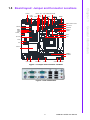
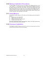
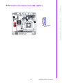
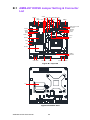
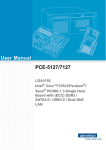
AUDIO1
LAN1
USB01
CMOS1 SPI1 VGA COMD3 JSETCOM3
LAN2
COM4
COMD12
BAT1 USB23 LPT1
KBMS1
FPAUD1
COM5678
Battery
SATA1
SATA2
ATX12V1
JCASE1
PCIEX1_1
GPIO1
SB: ICH7
LPC1
LVDS1
INV1
NB: G41
DIMMA1
CPUFAN1
USB1 USB2
ATXPWR1
PSON1
SYSFAN2 SYSFAN1
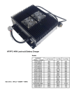
Figure 1.1 Jumper and Connector Location
Figure 1.2 I/O Connectors
5
AIMB-267 KIOSK User Manual
General Information
JOBS1+JWDT1+JFP3
JFP1+JFP2
Chapter 1
1.5 Board layout: Jumper and Connector Locations
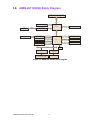
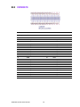
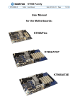
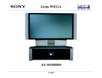
1.6 AIMB-267 KIOSK Block Diagram
CRT
VGA
Chrontel 7308B
SDVO
MHz FSB
1333/1066/800
Intel LGA775 Core 2 Quad/Core 2 Duo/
Pentium 4/Celeron Processor
Direct Media
Dual channel
LVDS
24-bit/channel
2x6W Amplifier
Audio Codec
Realtek ALC892
Intel HD Audio
2 SATA II
300 MB/s
8 USB 2.0
USB 2.0/1.1
Single Channel
DDR3 1066/800 MHz
PCIex1
PCIex1 Edge Connector
PCIex1
RTL 8111E: LAN
PCIex1
RTL 8111E: LAN
Interface
Intel G41
LVDS
ICH7
CF
SPI
LPC Bus
BIOS
W83627UHG
Fintek
81216AD
3 x RS-232, 1 x RS-232/422/485
PS/2, Parallel, GPIO, WDT
4 x RS-232
Figure 1.3 AIMB-267 KIOSK Block Diagram
AIMB-267 KIOSK User Manual
6
Warning! Always completely disconnect the power cord from your chassis whenever you work with the hardware. Do not make connections while the
power is on. Sensitive electronic components can be damaged by sudden power surges. Only experienced electronics personnel should open
the PC chassis.
Caution! The computer is provided with a battery-powered Real-time Clock circuit. There is a danger of explosion if battery is incorrectly replaced.
Replace only with same or equivalent type recommended by the manufacturer. Discard used batteries according to manufacturer's instructions.
Caution! There is a danger of a new battery exploding if it is incorrectly installed.
Do not attempt to recharge, force open, or heat the battery. Replace the
battery only with the same or equivalent type recommended by the manufacturer. Discard used batteries according to the manufacturer’s
instructions.
7
AIMB-267 KIOSK User Manual
General Information
Caution! Always ground yourself to remove any static charge before touching the
motherboard. Modern electronic devices are very sensitive to electrostatic discharges. As a safety precaution, use a grounding wrist strap at
all times. Place all electronic components on a static-dissipative surface
or in a static-shielded bag when they are not in the chassis.
Chapter 1
1.7 Safety Precautions
1.8 Jumper Settings
This section provides instructions on how to configure your motherboard by setting
the jumpers. It also includes the motherboards's default settings and your options for
each jumper.
1.8.1 How to set jumpers
You can configure your motherboard to match the needs of your application by setting the jumpers. A jumper is a metal bridge that closes an electrical circuit. It consists
of two metal pins and a small metal clip (often protected by a plastic cover) that slides
over the pins to connect them. To “close” (or turn ON) a jumper, you connect the pins
with the clip. To “open” (or turn OFF) a jumper, you remove the clip. Sometimes a
jumper consists of a set of three pins, labeled 1, 2, and 3. In this case you connect
either pins 1 and 2, or 2 and 3. A pair of needle-nose pliers may be useful when setting jumpers.
1.8.2 CMOS clear (CMOS1)
The AIMB-267 KIOSK motherboard contains a jumper that can erase CMOS data
and reset the system BIOS information. Normally this jumper should be set with pins
1-2 closed. If you want to reset the CMOS data, set J1 to 2-3 closed for just a few
seconds, and then move the jumper back to 1-2 closed. This procedure will reset the
CMOS to its default setting.
Table 1.3: CMOS1
Function
Jumper Setting
1
*Keep CMOS data
1-2 closed
1
Clear CMOS data
2-3 closed
*default setting
1.8.3 Chassis instruction connector (JCASE1)
The AIMB-267 KIOSK motherboard contains a jumper for a chassis open sensor.
When set, the buzzer on the motherboard beeps when the case is opened.
1.8.4 ATX/AT mode selector (PSON1)
Table 1.4: ATX/AT mode selector (PSON1)
Function
Jumper Setting
AT mode
1-2 closed
*ATX mode
2-3 closed
*default setting
AIMB-267 KIOSK User Manual
8
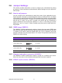
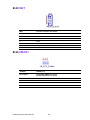
Users can use JSETCOM3 to select among RS 232/422/485 modes for COM3. The
default setting is RS 232.
RS232
RS422
RS485
Function
Jumper Setting
*RS232
(5-6) + (7-9) + (8-10) + (13-15) + (14-16) closed
RS422
(3-4) + (9-11) + (10-12) + (15-17) + (16-18) closed
RS-485
(1-2) + (9-11) + (10-12) + (15-17) + (16-18) closed
*: Default
1.8.6 JLVDS1/JLVDS2 Voltage Selector for LVDS1 Connector
Table 1.6: Voltage selector :
+3.3V
JLVDS1 1-2 short
+5V
JLVDS1 2-3 short
+12V
JLVDS1 pin 2 - JLVDS2 pin2 short)
1.9 System Memory
The AIMB-267 KIOSK has one socket for 240-pin DIMM x 1. All these sockets use
1.8v unbuffered double data rate synchronous DRAMs (DDR3 SDRAM). They are
available in capacities of 1024 MB and 2048 MB. The sockets can be filled in any
combination with DIMMs of any size, giving a total memory size on 4 GB. AIMB-267
KIOSK does NOT support ECC (error checking and correction).
9
AIMB-267 KIOSK User Manual
General Information
Table 1.5: COM3 RS 232/422/485 mode selector (JSETCOM3)
Chapter 1
1.8.5 COM3 RS 232/422/485 mode selector (JSETCOM3)
1.10 Memory Installation Procedures
To install DIMMs, first make sure the two handles of the DIMM socket are in the
“open” position. i.e. The handles lean outward. Slowly slide the DIMM module along
the plastic guides on both ends of the socket. Then press the DIMM module right
down into the socket, until you hear a click. This is when the two handles have automatically locked the memory module into the correct position of the DIMM socket. To
remove the memory module, just push both handles outward, and the memory module will be ejected by the mechanism in the socket.
1.11 Cache Memory
The AIMB-267 KIOSK supports a CPU with one of the following built-in full speed L2
caches:
6 MB for Intel Core 2 Quad CPU
6 MB for Intel Core 2 Duo CPU
1 MB for Intel Pentium Duo Core CPU
512 KB for Intel Celeron CPU
The built-in second-level cache in the processor yields much higher performance
than conventional external cache memories.
1.12 Processor Installation
The AIMB-267 KIOSK is designed for LGA775, Intel Core 2 Quad, Intel Core 2 Duo,
Celeron and Intel Pentium dual core D processor.
AIMB-267 KIOSK User Manual
10
Chapter
2
Connecting
Peripherals
2
2.1 Introduction
You can access most of the connectors from the top of the board as it is being
installed in the chassis. If you have a number of cards installed or have a packed
chassis, you may need to partially remove a card to gain access to all the connections.
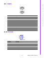
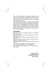
2.2 Parallel Port (LPT1)
LPT1
The parallel port is normally used to connect the motherboard to a printer. The AIMB267 KIOSK includes an onboard parallel port, accessed through a 25-pin flat-cable
connector, LPT1.
Table 2.1: Parallel Port (LPT1)
pin1
LPT1_a_STB#
pin2
LPT1_AFD#
pin3
LPT1_a_PD0
pin4
LPT1_ERR#
pin5
LPT1_a_PD1
pin6
LPT1_INIT#
pin7
LPT1_a_PD2
pin8
LPT1_SLIN#
pin9
LPT1_a_PD3
pin10
GND
pin11
LPT1_a_PD4
pin12
GND
pin13
LPT1_a_PD5
pin14
GND
pin15
LPT1_a_PD6
pin16
GND
pin17
LPT1_a_PD7
pin18
GND
pin19
LPT1_ACK#
pin20
GND
pin21
LPT1_BUSY
pin22
GND
pin23
LPT1_PE
pin24
GND
pin25
LPT1_SLCT
pin26
GND
AIMB-267 KIOSK User Manual
12
The parallel cable is not enclosed in the box as a standard accessory.
The order part number is 1700008809.
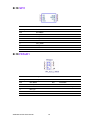
The AIMB-267 KIOSK provides up to eight USB ports (Universal Serial Bus). The
USB interface complies with USB Specification Rev. 2.0 supporting transmission
rates up to 480 Mbps and is fuse protected. The USB interface can be disabled in the
system BIOS setup.
The AIMB-267 KIOSK is equipped with two high-performance 1000 Mbps Ethernet
LANs. They are supported by all major network operating systems. The RJ-45 jack is
on the rear plate providing 1000Base-T operation.
LAN2_USB23/LAN1_USB01
USB1/2
Table 2.2: LAN LED Indicator
LAN Mode
Lan Indicator
1 Gbps Link on
LED1 Green on
100 Mbps Link on
LED1 Orange on
Active
LED2 Green flash
13
AIMB-267 KIOSK User Manual
Connecting Peripherals
2.3 USB Ports (LAN1_USB01/LAN2_USB23/USB1/
USB2)
Chapter 2
Note!
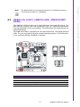
2.4 VGA Connector (VGA1)
VGA1
The AIMB-267 KIOSK includes a VGA interface that can drive conventional CRT displays. VGA1 is a standard 15-pin D-SUB connector commonly used for VGA. Pin
assignments for CRT connector VGA1 are detailed in Appendix B.
AIMB-267 KIOSK User Manual
14
Chapter 2
2.5 Serial Ports (COM1~COM8)
COM1/COM2/COM3
COM5678
AIMB-267 KIOSK supports eight serial ports - seven RS-232, and one RS-232/422/
485 - COM3. The user can use JSETCOM3 to select among RS 232/422/485 modes
for COM3. These ports can connect to serial devices, such as a mouse or a printer,
or to a communications network.
The IRQ and address ranges for both ports are fixed. However, if you want to disable
the port or change these parameters later, you can do this in the system BIOS setup.
Different devices implement the RS-232/422/485 standards in different ways. If you
are having problems with a serial device, be sure to check the pin assignments for
the connector.
15
AIMB-267 KIOSK User Manual
Connecting Peripherals
COM4
2.6 PS/2 Keyboard and Mouse Connector (KBMS1)
KBMS1
Two 6-pin mini-DIN connectors (KBMS1) on the motherboard provide connection to a
PS/2 keyboard and a PS/2 mouse, respectively.
AIMB-267 KIOSK User Manual
16
Chapter 2
2.7 CPU Fan Connector (CPU_FAN1)
NC
CPU_FAN1
If a fan is used, this connector supports cooling fans of 500 mA (6 W) or less.
17
AIMB-267 KIOSK User Manual
Connecting Peripherals
1
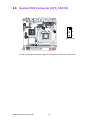
2.8 System FAN Connector (SYS_FAN1/2)
1
2
3
SYS_FAN1/2
If a fan is used, this connector supports cooling fans of 500 mA (6 W) or less.
AIMB-267 KIOSK User Manual
18
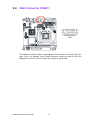
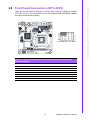
There are several external switches to monitor and control the AIMB-267 KIOSK.
JFP1+JFP2 are for the front panel (Power switch/Reset/HDD LED/SNMP SMBus/
Internal buzzer/External speaker).
Table 2.3: Power Switch/RESET/HDD LED/SM Bus/Internal Buzzer/
External Speaker
Closed Pins
Results
3-6
Power Button
9-12
SYstem Reset
2-5
HDD LED
8-11
SNMP SMBus
7-10*
Internal Buzzer*
1, 10
External Speaker
* Default
19
AIMB-267 KIOSK User Manual
Connecting Peripherals
*Intenal Buzzer 7-10 closed
Chapter 2
2.9 Front Panel Connectors (JFP1+JFP2)
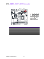
2.10 JOBS1+JWDT1+JFP3 Connector
*Watchdog Ouput to System
Reset 4-6 closed
*OSB Alarm 8-10 closed
Table 2.4: JOBS1+JWDT1+JFP3 Connector
Closed Pins
Results
1-5
Front Panel Power LED
7-9
Keyboard Lock
4-6*
Watchdog Output to System Reset*
8-10*
OSB Alarm*
* Default
AIMB-267 KIOSK User Manual
20
2.12 Serial ATA Interface (SATA1+SATA2)
AIMB-267 KIOSK features two high performance serial ATA interface (up to 300 MB/
s) which eases cabling to hard drives with thin and long cables.
21
AIMB-267 KIOSK User Manual
Connecting Peripherals
AUDIO1
Chapter 2
2.11 Line In/Line Out/Mic In Connector (AUDIO1)
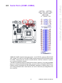
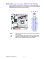
2.13 ATX Power Connector (ATX12V1+ATXPWR1)
These connectors are for ATX power supply plugs. The power supply plugs are
designed to fit these connectors in only one orientation. Find the proper orientation
and push down firmly until the connectors completely fit.
ATX12V
ATXPWR1
Note!
1.
2.
Please do connect the ATX12V1 connector with the PSU ATX 12V
4-pin connector.
For a fully configured system, we recommend that you use a power
supply unit (PSU) that complies with ATX 12 V Specification 2.0 (or
later version) and provides a minimum power of 270 W.
AIMB-267 KIOSK User Manual
22
Chapter 2
2.14 SPI BIOS Socket (SPI1)
2.15 Front Panel Audio Connector (FPAUD1)
This connector is for a chassis mounted front panel audio I/O module that supports
either HD Audio or legacy AC'97 (optional) audio standard. Connect one end of the
front panel audio I/O module cable to this connector.
FPAUD1
Note!
For motherboards with the optional HD audio feature, we recommend
that you connect a high-definition front panel audio module to this connector to avail of the motherboard’s high definition audio capability.
23
AIMB-267 KIOSK User Manual
Connecting Peripherals
SPI1
2.16 GPIO Pin Header (GPIO1)
GPIO1
2.17 LVDS Connector (LVDS1)
LVDS1
AIMB-267 KIOSK User Manual
24
Chapter 2
2.18 Inverter Connector for LVDS1 (INV1)
25
AIMB-267 KIOSK User Manual
Connecting Peripherals
INV1
AIMB-267 KIOSK User Manual
26
Chapter
3
BIOS Operation
3
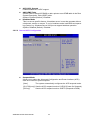
3.1 Main Menu
Press <Del> to enter AMI BIOS CMOS Setup Utility, the Main Menu will appear on
the screen. Use arrow keys to select among the items and press <Enter> to accept or
enter the sub-menu.
The Main BIOS setup screen has two main frames. The left frame displays all the
options that can be configured. Grayed-out options cannot be configured; options in
blue can. The right frame displays the key legend.
Above the key legend is an area reserved for a text message. When an option is
selected in the left frame, it is highlighted in white. Often a text message will accompany it.
System time / System date
Use this option to change the system time and date. Highlight System Time or
System Date using the <Arrow> keys. Enter new values through the keyboard.
Press the <Tab> key or the <Arrow> keys to move between fields. The date
must be entered in MM/DD/YY format. The time must be entered in HH:MM:SS
format.
AIMB-267 KIOSK User Manual
28
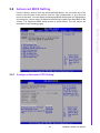
Use the <Arrow> keys to enter the Advanced BIOS Setup. You can select any of the
items in the left frame of the screen, such as CPU Configuration, to go to the sub
menu for that item. You can display an Advanced BIOS Setup option by highlighting it
and using the <Arrow> keys. All Advanced BIOS Setup options are described in this
section. The Advanced BIOS Setup screen is shown below. The sub menus are
described on the following pages.
Chapter 3
3.2 Advanced BIOS Setting
BIOS Operation
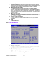
3.2.1 Configure Advanced CPU Setting
29
AIMB-267 KIOSK User Manual
Hardware Prefetcher
Hardware Prefetcher is a technique that fetches instructions and/or data from
memory into the CPU cache memory well before the CPU needs it. so that it can
improve the load-to-use latency You may choose to enable or disable it.
Adjacent Cache Line Prefetch
The Adjacent Cache-Line Prefetch mechanism, like automatic hardware
prefetch, operates without programmer intervention When enabled through the
BIOS, two 64-byte cache lines are fetched into a 128-byte sector, regardless of
whether the additional cache line has been requested or not. You may choose to
enable or disable it.
Max CPUID Value Limit
Setting this item to [Enabled] allows legacy operating systems to boot even
without support for CPUs with extended CPUID functions. Configuration options
are "Enabled" or "Disabled".
Execute-Disable Bit Capability
This item allows you to enable or disable the No-Execution page protection
technology.
PECI
Enable/Disable PECI.
3.2.2 IDE Configuration
ATA/IDE Configuration
This can be configured as Disabled or Enhanced. If enhanced mode is turned
on, primary, secondary and third IDE can be configured.
Hard Disk Write Protect
This will be effective only if the device is accessed through BIOS. You may
choose to enable or disable it.
IDE Detect Time Out (sec)
Select the time out value for detecting IDE devices.
AIMB-267 KIOSK User Manual
30
ATA (PI) 80 Pin Cable Detection
This item is for ATA 80 pin cable detection.
Chapter 3
3.2.3 Super I/O configuration
BIOS Operation
Serial Port Address
This item enables users to set the super I/O device status, including enabling of
COMs.
31
AIMB-267 KIOSK User Manual
Parallel Port Address
This configures parallel port base addresses. The following options are also
available:
– Parallel Port Mode
This option configures Parallel Port mode. Available options include ECP &
EPP/EPP/ECP/Bi-directional/Normal.
– Parallel Port IRQ
3.2.4 Hardware Health Configuration
Chassis Intrusion
Gives warning message beeping sounds when the case has been opened.
CPU warning temperature
Use this to set the CPU warning temperature threshold. When the system CPU
reaches the warning temperature, the buzzer will beep.
ACPI Shut Down Temperature
This screen allows users to set the CPU temperature at which the system will
automatically shut down to prevent the CPU from overheating damage.
System Temperature
The onboard hardware monitor automatically detects and displays the system
temperature.
CPU Temperature
The onboard hardware monitor automatically detects and displays the CPU
temperature.
CPU FAN Speed
Shows CPU FAN speed [xxxxRPM].
SYSTEMFAN1 Speed
Shows SYSTEMFAN1 speed [xxxxRPM].
AIMB-267 KIOSK User Manual
32
Chapter 3
3.2.5 ACPI Setting
BIOS Operation
3.2.5.1 Advanced ACPI Configuration
33
AIMB-267 KIOSK User Manual
ACPI APIC Support
Enable/Disable ACPI APIC support.
AMI OEMB Table
Set this value to allow ACPIBIOS to add a pointer to an OEMB table in the Root
System Description Table (RSDT) table.
Options: Enabled (Default) / Disabled.
Headless Mode
This is a server-specific feature. A headless server is one that operates without
a keyboard, monitor or mouse. To run in headless mode, both BIOS and operating system (e.g. Windows Server 2003) must support headless operation.
Options: Disabled (Default) / Enabled.
3.2.5.2 General ACPI Configuration
Suspend Mode
Allows you to select the Advanced Configuration and Power Interface (ACPI)
state to be used for system suspend.
[Auto]
The system automatically configures the ACPI suspend mode.
[S1 (POS) only] Sets the ACPI suspend mode to S1/POS (Power On Suspend).
[S3 only]
Sets the ACPI suspend mode to S3/STR (Suspend to RAM).
AIMB-267 KIOSK User Manual
34
Chapter 3
3.2.6 APM Configuration
BIOS Operation
Restore on AC Power Loss
When set to [Power Off], the system goes into an off state after an AC power
loss. When Set to [Power On], the system goes into an on state after an AC
power loss. When set to [Last State], the system goes into either an on or off
state - whatever the system state was before the AC power loss. Configuration
options:[Power Off][Power On][Last State].
Resume On Ring
This allows either settings of [Enabled] or [Disabled] for powering up the computer when the external modem receives a call while the computer is in Soft-off
mode. Configuration options:[Disabled][Enabled].
Resume On RTC Alarm
Allows you to enable or disable RTC to generate a wake event. When this item
is set to Enabled, the items RTC Alarm Date, RTC Alarm Hour, RTC Alarm
Minute, and RTC Alarm Second appear with set values. Configuration
options:[Disabled][Enabled].
35
AIMB-267 KIOSK User Manual
3.2.7 MPS Configuration
MPS Revision
This item will allow you to choose the version of MPS table to fit your OS system.
3.2.8 Smbios Configuration
AIMB-267 KIOSK User Manual
36
Smbios SMI support
Enable or disable the SMI wrapper support.
Chapter 3
3.2.9 USB Configuration
BIOS Operation
Legacy USB Support
This is for supporting USB device under legacy OS such as DOS. When choosing "AUTO", the system will automatically detect if any USB device is plugged
into the computer and enable USB legacy mode when a USB device is plugged
and disable USB legacy mode when no USB device is plugged.
USB 2.0 Controller Mode
This is to set speed of the USB 2.0 Controller.
BIOS EHCI Hand-off
This enables or disables supporting OS without EHCI hand-off feature.
37
AIMB-267 KIOSK User Manual
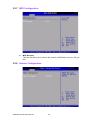
3.3 Advanced PCI/PnP Setting
Select the PCI/PnP tab from the AIMB-267 KIOSK setup screen to enter the Plug and
Play BIOS Setup screen. You can display a Plug and Play BIOS Setup option by
highlighting it using the <Arrow> keys. All Plug and Play BIOS Setup options are
described in this section. The Plug and Play BIOS setup screen is shown below.
AIMB-267 KIOSK User Manual
38
39
AIMB-267 KIOSK User Manual
BIOS Operation
Clear NVRAM
Set this value to force the BIOS to clear the Non-Volatile Random Access Memory {NVRAM). The Optimal and Fail-Safe default setting is No.
Plug and Play O/S
Set this value to allow the system to modify the settings for Plug and Play operating system support. The Optimal and Fail-Safe default setting is No.
PCI Latency Timer
Use this to adjust the PCI Latency Timer. This option sets the latency of all PCI
devices on the PCI bus. The Optimal and Fail-Safe default setting is 64.
Allocate IRQ to PCI VGA
Set this value to allow or stop the system from giving the VGA adapter card an
interrupt address. The Optimal and Fail-Safe default setting is Yes.
Palette Snooping
Set this value to allow the system to modify the Palette Snooping settings. The
Optimal and Fail-Safe default setting is "Disabled".
PCI IDE BusMaster
Set this value to allow or prevent the use of PCI IDE Busmastering. The Optimal
and Fail-Safe default setting is enabled.
Off Board PCI/ISA IDE card
Set this value to allow an add-on PCI/ISA IDE card to be selected. The Optimal
and Fail-Safe default setting is Auto.
IRQ
You may choose available or reserve. If you choose available, the IRQ will be
assigned to PCI.
DMA channel
You may choose available or reserve, If you choose available, the DMA channel
will be assigned to PCI.
Reserved memory size
Size of memory block to reserve for legacy ISA devices.
Chapter 3
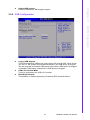
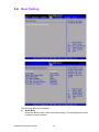
3.4 Boot Setting
The following options are available:
Quick Boot
Allows the BIOS to skip certain tests while booting. This will decrease the time
needed to boot the system.
AIMB-267 KIOSK User Manual
40
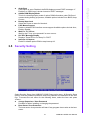
3.5 Security Setting
Select Security Setup from AIMB-267 KIOSK Setup main menu. All Security Setup
options, such as password protection and virus protection are described in this section. To access the sub menu for the following items, select the item and press
<Enter>:
change Supervisor / User Password
Provides for either installing or changing the password.
Boot Sector Virus Protection
The boot sector virus protection will warn if any program tries to write to the boot
sector.
41
AIMB-267 KIOSK User Manual
BIOS Operation
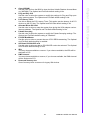
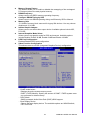
Quiet Boot
If this option is set to Disabled, the BIOS displays normal POST messages. If
Enabled, an OEM Logo is shown instead of POST messages.
AddOn ROM Display Mode
This is for choosing display mode of option ROM information under DOS environment during booting up process, Available options include Force BIOS, Keep
Current.
Bootup Num-Lock
Select the Power-on state for Numlock.
PS/2 Mouse Support
Enable or disable PS/2 interface mouse support Available options include Auto,
Enable, Disable.
Wait For 'F1' If Error
Wait for the F1 key to be pressed if an error occurs.
Hit 'DEL' Message Display
Displays "Press DEL to run Setup" in POST.
Interrupt 19 Capture
Enable or disable option ROM to trap interrupt 19.
Chapter 3
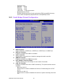
3.6 Advanced Chipset Setting
3.6.1 North Bridge Chipset Configuration
AIMB-267 KIOSK User Manual
42
– DVMT model select
Displays the active system memory mode.
DVMT / FIXED Memory: Specify the amount of DVMT / FIXED system memory to allocate for video memory.
– PAVP Mode
GMCH protected Audio Video Path (PAVP) BIOS support.
– Boot Display Device
Choose the boot display device. The available options are VBIOS default,
CRT and LVDS.
43
AIMB-267 KIOSK User Manual
BIOS Operation
Memory Remap Feature
The feature allows you to enable or disable the remapping of the overlapped
PCI memory above the total physical memory.
DRAM Frequency
Allows users to set DDR3 memory operating frequency.
Configure DRAM Timing by SPD
Allows users to set DRAM operating timing coefficients by SPD or Manual.
Memory Hole
15-16 MB of memory block reserved for legacy ISA devices. You may choose
disable and 15-16 MB.
Initiate Graphic Adapter
Allows users to set initial video output device. Available options include IGD,
PCI/ IGD.
Internal Graphics Mode Select
Allows users to set graphic mode for DOS environment. Available options
include Disable, Enable 32 MB, Enable 64 MB and Enable 128 MB.
PEG Port Configuration
Enabled/Disabled PEG port configuration.
Video Function Configuration
This allows users to set IGD (Integrated Graphics Device) configuration.
Chapter 3
– Flat Panel Type:
640x480
18-bit
800x600
18-bit
1024x768 18-bit
1600x1200 24-bit dual channel
– Spread Spectrum Clock
Enabling spread spectrum function gives better EMI compatibility but may
cause some unexpected peripheral device incompatibility issues.
3.6.2 South Bridge Chipset Configuration
USB Functions
Select: Disabled, 2 USB Ports, 4 USB Ports, 6 USB Ports or 8 USB Ports.
USB 2.0 Controller
Enables or disables the USB 2.0 controller.
Audio controller
Allows users to choose Auto or Azalia to manage the audio controller.
SMBUS Controller
Enables or disables the SMBUS controller.
SLP_S4# Min. Assertion Width
This item allows you to set a delay of a set number of seconds.
LAN 1/2 Controller
Enables or disables the LAN 1/2 GbE controller(s). The options below are also
available.
– Boot from LAN 1/2
Allows users to enable or disable the function of LAN booting from a PXE
server.
– Resume on LAN 1/2
Allows users to enable or disable the function of system resuming from LAN
1/2.
AIMB-267 KIOSK User Manual
44
Chapter 3
3.7 Exit Options
BIOS Operation
Save Changes and Exit
When you have completed system configuration, select this option to save your
changes, exit BIOS setup and reboot the computer so the new system configuration parameters can take effect.
1. Select Save Changes and Exit from the Exit menu and press <Enter>.
The following message appears:
Save Configuration Changes and Exit Now?
[Ok] [Cancel]
2. Select Ok or Cancel.
Discard Changes and Exit
Select this option to quit Setup without making any permanent changes to the
system configuration.
1. Select Save Changes and Exit from the Exit menu and press <Enter> The
following message appears:
Save Configuration Changes and Exit Now?
[Ok] [Cancel]
2. Select Ok to discard changes and exit
Discard Changes
Select Discard Changes from the Exit menu and press <Enter>.
Load Optimal Defaults
The AIMB-267 KIOSK automatically configures all setup items to optimal settings when you select this option. Optimal Defaults are designed for maximum
system performance, but may not work best for all computer applications. In
particular, do not use the Optimal Defaults if your computer is experiencing system configuration problems. Select Load Optimal Defaults from the Exit menu
and press <Enter>.
45
AIMB-267 KIOSK User Manual
Load Failsafe Defaults
The AIMB-267 KIOSK automatically configures all setup options to failsafe settings when you select this option. Failsafe Defaults are designed for maximum
system stability, but not maximum performance. Select Failsafe Defaults if your
computer is experiencing system configuration problems.
1. Select Load Failsafe Defaults from the Exit menu and press <Enter>. The
following message appears:
Load Failsafe Defaults?
[OK] [Cancel]
2. Select "OK" to load Failsafe defaults.
AIMB-267 KIOSK User Manual
46
Chapter
4
Chipset Software
Installation Utility
4
4.1 Before you begin
To facilitate the installation of the enhanced display drivers and utility software, read
the instructions in this chapter carefully. The drivers for AIMB-267 KIOSK are located
on the software installation CD. The driver in the folder of the driver CD will guide and
link you to the utilities and drivers under a Windows system. Updates are provided
via Service Packs from Microsoft*.
Note!
The files on the software installation CD are compressed. Do not
attempt to install the drivers by copying the files manually. You must use
the supplied SETUP program to install the drivers.
Before you begin, it is important to note that most display drivers need to have the
relevant software application already installed in the system prior to installing the
enhanced display drivers. In addition, many of the installation procedures assume
that you are familiar with both the relevant software applications and operating system commands. Review the relevant operating system commands and the pertinent
sections of your application software’s user manual before performing the installation.
4.2 Introduction
The Intel Chipset Software Installation (CSI) utility installs the Windows INF files that
outline to the operating system how the chipset components will be configured. This
is needed for the proper functioning of the following features:
Core PCI PnP services
IDE Ultra ATA 100/66/33 and Serial ATA interface support
USB 1.1/2.0 support (USB 2.0 driver needs to be installed separately for Win98)
Identification of Intel chipset components in the Device Manager
Integrates superior video features. These include filtered sealing of 720 pixel
DVD content, and MPEG-2 motion compensation for software DVD
Note!
This utility is used for the following versions of Windows, and it has to be
installed before installing all the other drivers:
Windows 7 (32-bit)
Windows 7 (64-bit)
Windows XP professional edition (32-bit)
Windows XP professional edition (64-bit)
AIMB-267 KIOSK User Manual
48
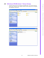
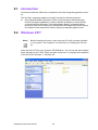
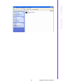
1.
Insert the driver CD into your system's CD-ROM drive. You can see the driver
folder items. Navigate to the "Chipset" folder and click "setup.exe" to complete
the installation of the driver.
Chapter 4
4.3 Windows XP/Windows 7 Driver Setup
Chipset Software Installation Utility
49
AIMB-267 KIOSK User Manual
AIMB-267 KIOSK User Manual
50
Chapter
5
VGA Setup
5
5.1 Introduction
You need to install the VGA driver to enable the Intel G41 integrated graphics controller.
The Intel G41 integrated graphics controller includes the following features:
Intel Graphics Media Accelerator X4500: Incorporating the latest Microsoft*
DirectX*9 support capabilities, it allows software developers to create lifelike
environments and characters. Dual independent display, enhanced display
modes for wide screen flat panels, and optimized 3D support delivers an intense
and realistic visual experience without requiring a separate graphics card.
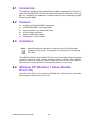
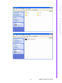
5.2 Windows XP/7
Note!
Before installing this driver, make sure the CSI utility has been installed
in your system. See Chapter 4 for information on installing the CSI utility.
Insert the driver CD into your system’s CD-ROM drive. You can see the driver folders
items. Navigate to the "VGA" folder and click "setup.exe" to complete the installation
of the drivers for Windows 7, Windows XP.
AIMB-267 KIOSK User Manual
52
Chapter 5
VGA Setup
53
AIMB-267 KIOSK User Manual
AIMB-267 KIOSK User Manual
54
Chapter
6
6
LAN Configuration
6.1 Introduction
The AIMB-267 KIOSK has dual Gigabit Ethernet LANs via dedicated PCI Express x1
lanes (Dual Realtek RTL8111E for LAN1 and LAN2) that offer bandwidth of up to 500
MB/ sec, eliminating the bottleneck of network data flow and incorporating Gigabit
Ethernet at 1000 Mbps.
6.2 Features
Integrated 10/100/100 BASE-T transceiver
10/100/1000 BASE-T triple-speed MAC
High-speed RISC core with 24-KB cache
On-chip voltage regulation
Wake-on-LAN (WOL) support
PCI Express X1 host interface
6.3 Installation
Note!
Before installing the LAN drivers, make sure the CSI utility has been
installed on your system. See Chapter 4 for information on installing the
CSI utility.
The AIMB-267 KIOSK's dual Realtek RTL8111E (LAN1 and LAN2) Gigabit integrated
controllers support all major network operating systems. However, the installation
procedure varies from system to system. Please find and use the section that provides the driver setup procedure for the operating system you are using.
6.4 Windows XP/ Windows 7 Setup (Realtek
RTL8111E)
Insert the driver CD into your system's CD-ROM drive. Select the Drv_LAN folder
then navigate to the directory for your OS.
AIMB-267 KIOSK User Manual
56
Chapter 6
LAN Configuration
57
AIMB-267 KIOSK User Manual
AIMB-267 KIOSK User Manual
58
Appendix
A
A
Programming the
Watchdog Timer
A.1 Programming the Watchdog Timer
The AIMB-267 KIOSK's watchdog timer can be used to monitor system software
operation and take corrective action if the software fails to function within the programmed period. This section describes the operation of the watchdog timer and how
to program it.
A.1.1 Watchdog timer overview
The watchdog timer is built into the super I/O controller W83627UHG. It provides the
following user-programmable functions:
Can be enabled and disabled by the user program
Timer can be set from 1 to 255 seconds or 1 to 255 minutes
Generates an interrupt or resets signal if the software fails to reset the timer
before time-out
A.1.2 Programming the Watchdog Timer
The I/O port address of the watchdog timer is 2E (hex) and 2F (hex). 2E (hex) is the
address port. 2F (hex) is the data port. You must first assign the address of register
by writing an address value into address port 2E (hex), then write/read data to/from
the assigned register through data port 2F (hex).
AIMB-267 KIOSK User Manual
60
Appendix A Programming the Watchdog Timer
Unlock W83627UHG
Select register of
watchdog timer
Enable the function of
the watchdog timer
Use the function of
the watchdog timer
Lock W83627UHG
61
AIMB-267 KIOSK User Manual
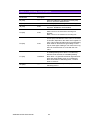
Table A.1: Watchdog Timer Registers
Address of register (2E) Attribute
Read/Write
Value (2F) &
description
87 (hex)
-----
Write this address to I/O address port 2E (hex)
twice to unlock the W83627UHG.
07 (hex)
write
Write 08 (hex) to select register of watchdog timer.
30 (hex)
write
Write 01 (hex) to enable the function of the watchdog timer. Disabled is set as default.
write
Set seconds or minutes as units for the timer.
Write 0 to bit 3: set second as counting unit.
[default]
Write 1 to bit 3: set minutes as counting unit.
write
0: stop timer [default]
01~FF (hex): The amount of the count, in seconds
or minutes, depends on the value set in register F5
(hex). This number decides how long the watchdog
timer waits for strobe before generating an interrupt or reset signal. Writing a new value to this register can reset the timer to count with the new
value.
F7 (hex)
read/write
Bit 7:Write 1 to enable mouse to reset the timer, 0
to disable[default]. Bit 6: Write 1 to enable keyboard to reset the timer, 0 to disable.[default]
Bit 5: Write 1 to generate a timeout signal immediately and automatically return to 0. [default=0]
Bit 4: Read status of watchdog timer, 1 means
timer is “timeout”.
AA (hex)
-----
Write this address to I/O port 2E (hex) to lock the
watchdog timer 2.
F5 (hex)
F6 (hex)
AIMB-267 KIOSK User Manual
62
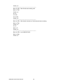
1. Enable watchdog timer and set 10 sec. as timeout interval
;----------------------------------------------------------Mov dx, 2Eh ; Unlock W83627UHG
Mov al, 87h
Out dx, al
Out dx, al
;----------------------------------------------------------Mov dx, 2Eh ; Select Logical Device 8 of watchdog timer
Mov al, 07h
Out dx, al
Inc dx
Mov al, 08h
Out dx, al
;----------------------------------------------------------Mov dx, 2Eh ; Set second as counting unit
Mov al, F5h
Out dx, al
Inc dx
In al, dx
And al, not 08h
Out dx, al
;----------------------------------------------------------Mov dx, 2Eh ; Set timeout interval as 10 seconds and start counting
Mov al, F6h
Out dx, al
Inc dx
Mov al,10
Out dx, al
;----------------------------------------------------------Mov dx, 2Eh; Lock W83627UHG
Mov al, AAh
Out dx, al
2. Enable watchdog timer and set 5 minutes as timeout interval
;----------------------------------------------------------Mov dx,2Eh ; Unlock W83627UHG
Mov al, 87h
Out dx, al
Out dx, al
;----------------------------------------------------------Mov dx,2Eh ; Select Logical Device 8 of watchdog timer
Mov al, 07h
Out dx, al
Inc dx
Mov al, 08h
63
AIMB-267 KIOSK User Manual
Appendix A Programming the Watchdog Timer
A.1.3 Example Program
Out dx, al
;----------------------------------------------------------Mov dx, 2Eh ; Set minutes as counting unit
Mov al, F5h
Out dx, al
Inc dx
In al, dx
Or al, 08h
Out dx, al
;----------------------------------------------------------Mov dx, 2Eh ; Set timeout interval as 5 minutes and start counting
Mov al, F6h
Out dx, al
Inc dx
Mov al, 5
Out dx, al
;----------------------------------------------------------Mov dx, 2Eh ; Lock W83627UHG
Mov al, AAh
Out dx, al
AIMB-267 KIOSK User Manual
64
Appendix
B
B
I/O Pin Assignments
B.1 AIMB-267 KIOSK Jumper Setting & Connector
List
AUDIO1
LAN1
USB01
CMOS1 SPI1 VGA COMD3 JSETCOM3
LAN2
COM4
COMD12
BAT1 USB23 LPT1
KBMS1
JOBS1+JWDT1+JFP3
JFP1+JFP2
FPAUD1
COM5678
Battery
SATA1
SATA2
ATX12V1
JCASE1
PCIEX1_1
GPIO1
SB: ICH7
LPC1
LVDS1
INV1
NB: G41
DIMMA1
CPUFAN1
USB1 USB2
ATXPWR1
PSON1
SYSFAN2 SYSFAN1
Figure B.1 Top View
CF1
Figure B.2 Bottom View
AIMB-267 KIOSK User Manual
66
LPT1
Printer Port connectors
Description
Printer Port
Pin
Pin Name
Pin
Pin Name
1
LPT1_a_STB#
2
LPT1_AFD#
3
LPT1_a_PD0
4
LPT1_ERR#
5
LPT1_a_PD1
6
LPT1_INIT#
7
LPT1_a_PD2
8
LPT1_SLIN#
9
LPT1_a_PD3
10
GND
11
LPT1_a_PD4
12
GND
13
LPT1_a_PD5
14
GND
15
LPT1_a_PD6
16
GND
17
LPT1_a_PD7
18
GND
19
LPT1_ACK#
20
GND
21
LPT1_BUSY
22
GND
23
LPT1_PE
24
GND
25
LPT1_SLCT
B.3 USB1 / USB2
USB1/USB2
Two USB ports
Description
Two USB ports
Pin
Pin Name
Pin
Pin Name
1
+V5_USB
6
USB1P
2
+ V5_USB
7
GND
3
USB0N
8
GND
4
USB1N
5
USB0P
10
GND
67
AIMB-267 KIOSK User Manual
Appendix B I/O Pin Assignments
B.2 LPT1
B.4 USB/LAN
USB
USB ports
Pin
Signal
Pin
Signal
1
VCC
3
Data0+
2
Data0-
4
GND
LAN
Ethernet 10/100 Mbps RJ-45 port
Pin
Signal
Pin
Signal
1
XMT+
5
N/C
2
XMT-
6
RCV-
3
RCV+
7
N/C
4
N/C
8
N/C
B.5 VGA1
VGA1
VGA connector
Pin
Signal
Pin
Signal
1
RED
9
CRT_VCCIN
2
VGA_G
10
GND
3
VGA_B
11
N/C
4
N/C
12
V_SDAT
5
GND
13
H-SYNC
6
GND
14
V-SYNC
7
GND
15
V_SCLK
8
GND
AIMB-267 KIOSK User Manual
68
COM 1 ~ 3
COM 1 ~ 3 connectors
Pin
Signal
1
DCD
2
DSR
3
RXD
4
RTS
5
TXD
6
CTS
7
DTR
8
RRI
9
GND
Appendix B I/O Pin Assignments
B.6 COM1 ~ 3
B.7 COM4
INV1
COM4 connector
Description
COM4 connector
Pin
Pin Name
1
COM4_DCD#
2
COM4_DSR#
3
COM4_SIN
4
COM4_RTS#
5
COM4_SOUT
6
COM4_CTS#
7
COM4_DTR#
8
COM4_RI#
10
GND
69
AIMB-267 KIOSK User Manual
B.8 COM5678
COM5678
COM5678 connectors
Description
COM5678 connectors
Pin
Pin Name
Pin
Pin Name
1
COM5_DCD#
2
COM5_DSR#
3
COM5_SIN
4
COM5_RTS#
5
COM5_SOUT
6
COM5_CTS#
7
COM5_DTR#
8
COM5_RI#
9
GND
10
GND
11
COM6_DCD#
12
COM6_DSR#
13
COM6_SIN
14
COM6_RTS#
15
COM6_SOUT
16
COM6_CTS#
17
COM6_DTR#
18
COM6_RI#
19
GND
20
GND
21
COM7_DCD#
22
COM7_DSR#
23
COM7_SIN
24
COM7_RTS#
25
COM7_SOUT
26
COM7_CTS#
27
COM7_DTR#
28
COM7_RI#
29
GND
30
GND
31
COM8_DCD#
32
COM8_DSR#
33
COM8_SIN
34
COM8_RTS#
35
COM8_SOUT
36
COM8_CTS#
37
COM8_DTR#
38
COM8_RI#
39
GND
40
GND
AIMB-267 KIOSK User Manual
70
KBMS1
Keyboard and mouse connector
Pin
Signal
1
KB DATA
2
N/C
3
GND
4
KB VCC
5
KC CLK
6
N/C
7
M_DATA
8
N/C
9
GND
10
M_VCC
11
M_CLK
12
N/C
Appendix B I/O Pin Assignments
B.9 KBMS1
B.10 CPUFAN1
CPUFAN1
CPU FAN
Description
CPU FAN connector
Pin
Pin Name
1
GND
2
CPU_FAN_PWN
3
CPU_FAN_SPEED
4
N/A
71
AIMB-267 KIOSK User Manual
B.11 SYSFAN1~2
SYSFAN1
SYS FAN
Description
SYS FAN connector
Pin
Pin Name
1
GND
2
SYS_FAN_PWN
3
SYS_FAN_SPEED
B.12 JFP1+JFP2
JFP1+JFP2
Front Panel
Description
PWRBTN#(3-6) /RESET#(9-12) /HDD LED(2-5) /SNMP SMBus(811) / Internal Buzzer(7-10 short) /External speaker(1-10)
Pin
Pin Name
1
SPK_CN17P1
2
+ V3.3
3
PANSWIN#
4
SPK_CN17P2
5
SATALED#
6
GND
7
SPK_CN17P3
8
SMB_DATA
9
SYS_RST#
10
SPK_CN17P4
11
SMB_CLK
12
GND
AIMB-267 KIOSK User Manual
72
JOBS1+JWDT1+JFP2 OBS / Watch Dog / Front Panel
Description
Front Panel-PWR LED(1-5) & KB LOCK#(7-9)
Watch dog output to Reset# (4-6 short)
OSB enable(8-10 short)
Pin
Pin Name
1
+V3.3
2
N/A
3
N/A
4
SIO_WG#
5
GND
6
SYS_RESET#
7
SIO_SUSLED
8
SIO_BEEP
9
KEYLOCK#
10
OBS_BEEP
B.14 Audio1
Audio1
Audio connector
Pin
Signal
1
Line in
2
Line out
3
Mic in
73
AIMB-267 KIOSK User Manual
Appendix B I/O Pin Assignments
B.13 JOBS1+JWDT1+JFP3
B.15 SATA1~2
SATA1~2
SATA CON
Description
SATA connector SATA II 3Gb/s
Pin
Pin Name
1
GND
2
TX+
3
TX-
4
GND
5
RX-
6
RX+
7
GND
B.16 ATX12V1
EATXPWR2
ATX Power Input
Description
ATX 4 pin main power connector
Pin
Pin Name
1
GND
2
GND
3
+V12_4P
4
+V12_4P
AIMB-267 KIOSK User Manual
74
ATXPWR1
ATX Power Input
Description
ATX 20 pin main power connector
Pin
Pin Name
1
+V3.3
2
+V3.3
3
GND
4
+V5
5
GND
6
+V5
7
GND
8
ATXPG
9
+V5_SB
10
+V12V
11
+V3.3
12
-V12
13
GND
14
PS_ON#
15
GND
16
GND
17
GND
18
-V5
19
+V5
20
+V5
75
Appendix B I/O Pin Assignments
B.17 ATXPWR1
AIMB-267 KIOSK User Manual
B.18 SPI1
SPI1
BIOS socket
Description
BIOS socket
Pin
Pin Name
1
SPI_CS#
2
SPI_MISO
3
SPI_WP#
4
GND
5
SPI_MOSI
6
SPI_CLK
7
HOLD
8
+V3.3
B.19 FPAUD1
FPAUD1
Audio front panel connector
Description
Audio front panel connector
Pin
Pin Name
Pin
Pin Name
1
MIC2_L
6
MIC2-JD
2
AGND
7
FRONT-IO-SENSE_R
3
MIC2_R
4
PRESENCE#
9
LINE2-L
5
LINE2-R
10
LINE2-JD
AIMB-267 KIOSK User Manual
76
GPIO1
GPIO CONNECT
Description
Digital IO connector
Pin
Pin Name
1
GPIO0
2
GPIO4
3
GPIO1
4
GPIO5
5
GPIO2
6
GPIO6
7
GPIO3
8
GPIO7
9
+V5
10
GND
77
Appendix B I/O Pin Assignments
B.20 GPIO1
AIMB-267 KIOSK User Manual
B.21 LVDS1
LVDS1
LVDS connector
Description LVDS connector
Pin
Pin Name
Pin
Pin Name
Pin
Pin Name
1
VDD_LVDS1
15
LA_DATAP1
29
GND
2
VDD_LVDS1
16
LB_DATAP1
30
GND
3
GND
17
GND
31
L_DDC_CLKR
4
GND
18
GND
32
L_DDC_DATR
5
VDD_LVDS1
19
LA_DATAN2
33
GND
6
VDD_LVDS1
20
LB_DATAN2
34
GND
7
LA_DATAN0
21
LA_DATAP2
35
LA_DATAN3
8
LB_DATAN0
22
LB_DATAP2
36
LB_DATAN3
9
LA_DATAP0
23
GND
37
LA_DATAP3
10
LB_DATAP0
24
GND
38
LB_DATAP3
11
GND
25
LA_CLKN
39
L_BKLTEN
12
GND
26
LB_CLKN
40
VCON (VESA /
JEIDA select)
13
LA_DATAN1
27
LA_CLKP
14
LB_DATAN1
28
LB_CLKP
AIMB-267 KIOSK User Manual
78
Appendix B I/O Pin Assignments
B.22 JSETCOM3
JSETCOM3
Description
RS232/422/485 SEL. JUMPER
Pin
Pin Name
1
UART3_SIN
2
RXD485_3
3
UART3_SIN
4
RXD422_3
5
UART3_SIN
6
RXD232_3
7
DCDC3
8
SOUT3
9
COM3_DCD#
10
COM3_SOUT
11
COM3_TXD485N
12
COM3_RXD485P
13
SIN3
14
DTR3
15
COM3_SIN
16
COM3_DTR#
17
COM3_TXD485P
18
COM3_RXD485N
79
AIMB-267 KIOSK User Manual
B.23 INV1
INV1
Inverter connector for LVDS1
Description
Inverter connector for LVDS1
Pin
Pin Name
1
+V12_INV1
2
GND
3
LVDS1_ENBKL
4
SIO_VCON (Liner brightness setting)
5
+V5_INV1
B.24 CMOS1
JCMOS1
CMOS clear
Description
Clear BIOS CMOS (2-3 short)
Normal operation (1-2 short)
Pin
Pin Name
1
RTCRST#
2
RTCRST#
3
GND
AIMB-267 KIOSK User Manual
80
PSON1
AT/ATX feature selection
Description
ATX mode (2-3 short)
AT mode (1-2 short)
Pin
Pin Name
1
AT
2
+V3.3
3
ATX
Appendix B I/O Pin Assignments
B.25 PSON1
B.26 JLVDS1 / JLVDS2
JLVDS1 / JLVDS2
Voltage selector for LVDS1 connector
Description
Voltage selector :
+V3.3 (JLVDS1 1-2 short)
+V5 (JLVDS1 2-3 short)
+V12 (JLVDS1 pin 2 - JLVDS2 pin2 short)
JLVDS1
Pin
Name
1
+V3.3
2
+V_LCD_S (LCD power)
3
+V5
JLVDS2
Pin
Name
1
NC
2
+V12
81
AIMB-267 KIOSK User Manual
B.27 JCASE1
JCASE1
JCASE OPEN
Description
JCASE OPEN connector
Pin
Pin Name
1
CASEOP#
2
GND
B.28 BAT1
BAT1
Battery socket
Description
Battery socket
Pin
Pin Name
1
+VBAT
2
GND
3
N/A
B.29 DMA Channel Assignments
Channel
Function
0
Available
1
Available
2
Available
3
ECP Printer Port (LPT1)
4
Direct Memory Access Controller
5
Available
6
Available
7
Available
AIMB-267 KIOSK User Manual
82
Priority
Interrupt#
Interrupt Source
1
NMI
Parity error detected
2
IRQ0
System timer
3
IRQ1
Standard 101/102-key or Microsoft Natural PS/2 keyboard
-
IRQ2
Interrupt form controller 2 (cascade)
4
IRQ8
Real-time clock
5
IRQ9
Microsoft ACPI-Compliant system
6
IRQ10
Serial communication port 4
7
IRQ11
Serial communication port 5/6/7/8
8
IRQ12
PS/2 mouse
9
IRQ13
Numeric data processor
10
IRQ14
Primary IDE channel
11
IRQ15
Secondary IDE channel
12
IRQ3
Serial communication port 2
13
IRQ4
Serial communication port 1
14
IRQ5
Serial communication port 3
15
IRQ6
Available
16
IRQ7
Available
B.31 1st MB Memory Map
Address Range (Hex)
Device
E000h - FFFFFh
BIOS
CC800h - DFFFFh
Unused
C0000h - CC7FFh
VGA BIOS
A0000h - BFFFFh
Video memory
)))))h - 9FFFFh
Base memory
83
AIMB-267 KIOSK User Manual
Appendix B I/O Pin Assignments
B.30 Interrupt Assignments
www.advantech.com
Please verify specifications before quoting. This guide is intended for reference
purposes only.
All product specifications are subject to change without notice.
No part of this publication may be reproduced in any form or by any means,
electronic, photocopying, recording or otherwise, without prior written permission of the publisher.
All brand and product names are trademarks or registered trademarks of their
respective companies.
© Advantech Co., Ltd. 2012