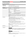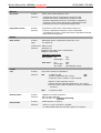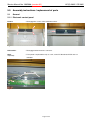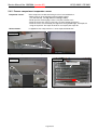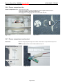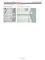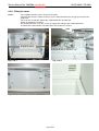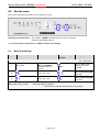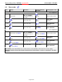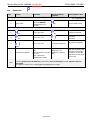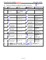
1
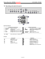
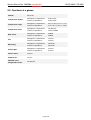
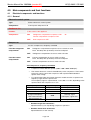
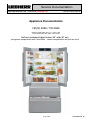
After Sales Service International Service Documentation Service Manual No. 199/2008 (version 02) LWL/KDT/baj/23.08.10 Appliance Documentation HC(S) 2062 / CS 2062 ECN(es) 6256 index 10 to 11 / version 337 CNes 6256 index 10 to 10B / version 337 NoFrost combined fridge-freezer 36’’ wide (91 cm) (refrigerator compartment with FrenchDoor – freezer compartment with pull-out units) Page 1/39 199200802SM_gb Service Manual No. 199/2008 (version 02) HC(S) 2062 / CS 2062 Contents 1.0 2.0 3.0 3.1 3.2 4.0 4.1 Operating and control elements............................................................................................. 3 Functions at a glance.............................................................................................................. 4 Description of the appliance................................................................................................... 5 Sensor positions, schematic diagrams ...................................................................................... 6 Socket construction, schematic diagram ................................................................................... 6 Main components and their functions ................................................................................... 7 Electrical components and functions ......................................................................................... 7 4.1.1 General.................................................................................................................................................. 7 4.1.2 Refrigerator compartment ..................................................................................................................... 8 4.1.3 Freezer compartment ............................................................................................................................ 9 4.2 Refrigeration components and functions ................................................................................. 11 4.2.1 General................................................................................................................................................ 11 4.2.2 Refrigerator compartment ................................................................................................................... 11 4.2.3 Freezer compartment .......................................................................................................................... 11 5.0 Assembly instructions / replacement of parts .................................................................... 12 5.1 General ................................................................................................................................... 12 5.1.1 5.1.2 5.1.3 5.1.4 5.1.5 5.1.6 Electronic control panel ....................................................................................................................... 12 Electronic power module ..................................................................................................................... 13 Condenser fan..................................................................................................................................... 15 Refrigerator door replacement ............................................................................................................ 16 Heating FrenchDoor seal .................................................................................................................... 18 Heating FrenchDoor seal (New seal profile at HC(S) 2062 from index 11) ........................................ 19 5.2 Refrigerator compartment........................................................................................................ 20 5.2.1 5.2.2 5.2.3 5.2.4 5.2.5 Disassembling the refrigerator compartment evaporator cover .......................................................... 20 Refrigerator compartment air sensor .................................................................................................. 21 Refrigerator compartment evaporator sensor ..................................................................................... 21 Refrigerator compartment fan ............................................................................................................. 22 Fitting the cover ................................................................................................................................... 22 5.3 Freezer compartment .............................................................................................................. 23 5.3.1 5.3.2 5.3.3 5.3.4 5.3.5 5.3.6 5.3.7 5.3.8 6.0 6.1 6.2 6.3 7.0 8.0 8.1 8.2 8.3 8.4 Dismantling of freezer drawers............................................................................................................ 23 Freezer compartment evaporator cover .............................................................................................. 24 Freezer compartment air sensor ......................................................................................................... 25 Temperature limiter ............................................................................................................................. 25 Freezer compartment evaporator sensor............................................................................................ 26 Freezer compartment fan.................................................................................................................... 27 Freezer compartment reed contact ..................................................................................................... 27 Fitting the cover ................................................................................................................................... 29 Technical data ....................................................................................................................... 30 General ................................................................................................................................... 30 Refrigerator compartment........................................................................................................ 30 Freezer compartment .............................................................................................................. 30 Customer menu ..................................................................................................................... 31 Service menu ......................................................................................................................... 32 Manual defrosting .................................................................................................................... 32 Demo mode............................................................................................................................. 33 Panel test ................................................................................................................................ 34 Sensor test (display of temperature) and door contact test...................................................... 35 8.4.1 IceMaker.............................................................................................................................................. 36 8.5 Service mode .......................................................................................................................... 37 8.5.1 Refrigerator/freezer compartment ....................................................................................................... 37 8.5.2 IceMaker.............................................................................................................................................. 38 8.5.3 solenoid valve...................................................................................................................................... 39 9.0 Error codes ............................................................................................................................ 39 Page 2/39 Service Manual No. 199/2008 (version 02) HC(S) 2062 / CS 2062 1.0 Operating and control elements 14 11 15 10 1 2 3 4 12 16 13 5 6 7 8 9 22 20 17 18 19 21 23 Operating elements: 1 2 3 4 10 Refrigerator compartment SuperCool SuperCool function ON/OFF ON/OFF button for refrigerator compartment Up Setting button temperature higher Down Setting button temperature lower Alarm 5 6 7 8 9 General Alarm OFF button for audible alarm Freezer compartment Setting button temperature higher Setting button temperature lower ON/OFF button for freezer compartment SuperFrost SuperFrost function IceMaker ON/OFF button for IceMaker Up Down ON/OFF Controls: 11 12 13 14 15 16 Front panel Power failure SuperCool activated Child lock activated Alarm IceMaker ON SuperFrost activated 17 18 19 20 21 22 23 Page 3/39 MagicEye Change water filter Sabbath mode activated Customer menu activated Temperature display in °C Temperature display in °F Refrigerator compartment temperature Freezer compartment temperature Service Manual No. 199/2008 (version 02) HC(S) 2062 / CS 2062 2.0 Functions at a glance Control: Electronic Temperature display: Refrigerator compartment: Freezer compartment: Temperature range: Refrigerator compartment: Freezer compartment: Temperature alarm: Refrigerator compartment: Freezer compartment: Not present Visual, audible Door alarm: Refrigerator compartment: Freezer compartment: Audible Audible Fan: Refrigerator compartment: Freezer compartment: Present Present Defrosting: Refrigerator compartment: Freezer compartment: Automatic Automatic Interior light: Refrigerator compartment: Freezer compartment: Present Present Service menu: Present Compressor: 2x VCC Solenoid valve refrigeration circuit: Not present Actual value Actual value 35°F to 44°F (+2°C to +7°C) -15°F to 6°F (-14°C to -26°C) Page 4/39 Service Manual No. 199/2008 (version 02) HC(S) 2062 / CS 2062 3.0 Description of the appliance The HC(S)/CS 2062 is a combined fridge-freezer with a freely suspended rear wall evaporator in the refrigerator compartment and a NoFrost freezer compartment with IceMaker. The temperature in the refrigerator compartment is controlled by an air sensor and an evaporator sensor. The temperature in the freezer compartment is likewise controlled by an air sensor. The appliance has 2 frequency-controlled compressors. Therefore the refrigerator compartment and freezer compartment have a separate refrigeration circuit and can be controlled separately. The freezer compartment is equipped with a NoFrost rear wall evaporator module, fan module, air sensor and evaporator sensor. The defrosting phases are initiated by way of the electronic control system. taking compressor running time and door openings into account. There is an automatic IceMaker in the freezer compartment. Page 5/39 Service Manual No. 199/2008 (version 02) 3.1 HC(S) 2062 / CS 2062 Sensor positions, schematic diagrams Front panel with control panel PCB and 2 reed PCBs Refrigerator compartment air sensor Refrigerator compartment evaporator sensor Cover for refrigerator compartment Freezer compartment Freezer compartment Condenser Power PCB Fig. 3.1/ 2 Fig. 3.1/ 1 3.2 Socket construction, schematic diagram Refrigerator compartment compressor Freezer compartment compressor Power PCB Condenser fan Filter Page 6/39 Service Manual No. 199/2008 (version 02) HC(S) 2062 / CS 2062 4.0 Main components and their functions 4.1 Electrical components and functions 4.1.1 General Electronic control system Type: Series 6 electronic control system Components: Control panel and power PCB Condenser fan Position: In the socket of the appliance Components: ON: Refrigerator compartment compressor ON Freezer compartment compressor ON OFF: Both compressors OFF or Compressor Type: Function refrigerator compartment: Function freezer compartment: 2 x VCC compressors, frequency controlled ON: Refrigerator compartment evaporator sensor switch-on value Note: On-delay time (8 minutes) must have elapsed. OFF: Refrigerator compartment air sensor switch-off value ON: Freezer compartment air sensor switch-on value Note: On-delay time (8 minutes) must have elapsed. OFF: Freezer compartment air sensor switch-off value VCC compressor, frequency-controlled. • Compressor with 4 different speeds (1600 / 1900 / 3000 / 3600 rpm). • The inverter electronic control is fitted directly on the compressor. The inverter electronic control controls the compressor with a pulse-width modulated square-wave voltage. • For speed value input, the inverter electronic module receives a square wave frequency signal from the power PCB. This frequency signal is output with 56, 71, 87,100 or 117 Hz, depending on the speed at which the compressor is to run. Frequency in Hz 56 71 87 100, 0 (signal interruption), other values than the defined frequencies 117 Speed in rpm Compressor OFF 1600 1900 Operation Compressor OFF Ideal case Control mode 3000 Start-up, signal interruption, signal fault 3600 SuperFrost • Runtime longer than 70 minutes: Speed increase by one step during compressor operation. • Runtime shorter than 50 minutes: Speed reduction on next start-up. Page 7/39 Service Manual No. 199/2008 (version 02) HC(S) 2062 / CS 2062 4.1.2 Refrigerator compartment Electronic control system Setting range: Refrigerator compartment: 35°F to 44°F (+2°C to +7°C) Display range: 32°F to 118°F (0°C to 48°C) (actual value display) Temperatures equal to/colder than 32°F (0°C) are displayed with 32°F (0°C). Functions SuperCool: SuperCool ON: Refrigerator compartment sets itself to 35°F (2°C) for 6 hours. SuperCool OFF: The refrigerator compartment sets itself to the set value. Defrosting: Automatic during compressor standstill phase. Door alarm: When: If door is open, after 60 seconds. Audible: 3 beeps. Position: In the vertical cover. Function: - Switches OFF the refrigerator compartment compressor. - Generates the refrigerator compartment temperature display Sensors Refrigerator compartment air sensor: value. Evaporator sensor: Position: In the sensor holder on the back of the evaporator. Function: - Switches ON the refrigerator compartment compressor. - Ends the defrosting phase. Position: In front panel. Type: 2 x reed PCB Switch Door switch: Contact type: Make contact Function: Activation via: Magnet on both doors, magnet is replaceable. Switching signal when: doors closed: fan interior light ON OFF doors open: OFF ON ON after 60 seconds fan interior light door alarm Loads Position: Centre of liner ceiling, behind vertical separating plate. Function: Fan runs in parallel with compressor. Control: 11V/DC Refrigerator compartment interior light: Position: Inside right and left Function: - Shines as soon as the door is opened. - Is switched OFF after door has been open for 15 minutes. Heater for FrenchDoor-gasket: Position: mounted in each FrenchDoor-gasket Function: If neccessary it can be activated by the costumer (condensation) (see chapter 7.0.) Fan: Page 8/39 Service Manual No. 199/2008 (version 02) HC(S) 2062 / CS 2062 4.1.3 Freezer compartment Electronic control system Setting range: -15°F to 6°F (-14°C to -26°C) Display range: 32°F to -58°F (0°C to -50°C) (actual value display) Values above 32°F (0°C) are indicated by a dash. Functions Temperature alarm: Alarm value: 4K warmer than set value. SuperFrost alarm value: 14°F (-10°C). Delay: 20 minutes. Visual: Flashing temperature display. Audible: 4 beeps. During start-up: is reached, The temperature display flashes until the switch-off value the audible alarm is switched OFF. (E.g. given a set value of 0°F (-18°C), a temperature of 7°F (–14°C) has to be present for at least 20 minutes, then a temperature alarm is activated.) When the defrosting phase begins, the temperature alarm is suppressed for 1.5 hrs. Defrosting: The defrosting phase is initiated: - During start-up after 6 hours cumulative compressor running time. - After a cumulative compressor running time of 12 to 24 hours maximum, depending on the number/duration of the door openings. As the defrosting phase begins, the compressor and fan are switched OFF and the defrost heater is switched ON. The defrost heater remains switched ON until such time as - the freezer compartment evaporator sensor has reached 41°F (+5°C) or - a max. defrosting time of 50 minutes has been reached. After the end of the heating phase, the compressor is switched on with a 5-minute delay. If the SuperFrost function is activated during the defrosting phase, this will not interrupt defrosting. Door alarm: SuperFrost: When: If door is open, after 60 seconds. Audible: 3 beeps. SuperFrost ON: The appliance sets itself to -29°F (-34°C) for at least 30 hours. In the following 35 hours SuperFrost ends automatically once the temperature falls 8K below the set value (at 0°F (-18°C) -> -15°F(-26°C)) or after the total time of 65 hours has elapsed. SuperFrost OFF: The freezer compartment sets itself to the set value. Attention: If SuperFrost is actuated during a defrosting phase, the SuperFrost function is not performed before the defrosting phase has run. Page 9/39 Service Manual No. 199/2008 (version 02) HC(S) 2062 / CS 2062 Sensors Air sensor: Evaporator sensor: Position: On the front of the evaporator cover. Function: - Switches the freezer compartment compressor ON. - Switches the freezer compartment compressor OFF. - Freezer compartment air sensor and freezer compartment evaporator sensor switch the freezer compartment fan ON - Generates the freezer compartment display value. Position: Inserted in the lower area of the lamellar evaporator. Function: - Freezer compartment evaporator sensor and freezer compartment air sensor, switch the freezer compartment fan ON. - Ends the defrosting phase. Position: Behind the freezer compartment evaporator cover. Type: 2 x reed PCB Switch Door switch: Contact type: Make contact Function: Activation via: Magnet in back right corner of the drawers. Magnet is replaceable. Switching signal when: door closed: fan interior light ON OFF door open: fan interior light door alarm OFF ON ON after 60 seconds Loads Fan: Position: Top centre of freezer compartment. Function: ON: - compressor ON - freezer compartment door closed - evaporator sensor switch-on value reached. and and Switch-on value evaporator sensor: a) during start-up / after defrosting phase: -4°F (-20°C). b) In the normal mode 2K colder than freezer compartment air sensor. OFF: Defrost heater: Interior light: - Compressor OFF Position: Clipped into lamellar evaporator. Function: Defrosts the evaporator. For activation, see: Functions Defrosting Position: Underneath the crosspiece. Function: - Shines as soon as the door is opened. - Is switched OFF after door has been open for 15 minutes. Page 10/39 Service Manual No. 199/2008 (version 02) 4.2 HC(S) 2062 / CS 2062 Refrigeration components and functions 4.2.1 General Compressor Compressor: 2x VCC 4.2.2 Refrigerator compartment Evaporator Type: Rear wall evaporator Type of installation: Suspended freely. Injection point: At the top left 4.2.3 Freezer compartment Evaporator Type: Lamellar evaporator Type of installation: Freestanding between air duct panel and compartment liner. Injection point: Top right on lamellar evaporator. Page 11/39 Service Manual No. 199/2008 (version 02) HC(S) 2062 / CS 2062 5.0 Assembly instructions / replacement of parts 5.1 General 5.1.1 Electronic control panel Covers: - Disengage the covers at the marked locations. Fig. 5.1.1/ 1 Fig. 5.1.1/ 2 PCB carrier: - Disengage and remove bus connector. Note: separately - Front panel is replaceable only as a unit, control PCB and reed PCBs are not available! Reed PCBs Fig. 5.1.1 / 3 Page 12/39 Service Manual No. 199/2008 (version 02) HC(S) 2062 / CS 2062 5.1.2 Electronic power module Ventilation panel: - Remove ventilation panel. - Remove cover. Cover Fig. 5.1.2 / 1 Cable clip: - Unclip the cable clip at the marked location and unscrew the strain relief. - Detach front PCB edge connectors. Fig. 5.1.2 / 2 Page 13/39 Service Manual No. 199/2008 (version 02) PCB carrier: HC(S) 2062 / CS 2062 - Unclip the PCB carrier at the left and right and draw it out of the unit carrier. - Detach the feed cable and rear PCB edge connectors (sensor, reed conduct, bus line). Fig. 5.1.2 / 3 Electronic power module: Fig. 5.1.2/ 4 - Disengage the upper part of the plug-in unit at the marked locking hooks and remove it. - Disengage the PCB at the marked locations. Fig. 5.1.2/ 5 Page 14/39 Service Manual No. 199/2008 (version 02) HC(S) 2062 / CS 2062 5.1.3 Condenser fan Removal: - Loose the fastening screw and remove the protection grill. - Pull off the fan blade. - Plug of the motor. Protection grill Filter Fig. 5.1.3/ 1 Removal: Fig. 5.1.3/ 2 - Grap into the hole and strip off the motor from the rear base. - Pull out the angle of the motor through the front base (rubber ring remains on the base). Motor Rear base Plug Rear rubber ring Front base with rubber ring Fig. 5.1.3/ 3 Fig. 5.1.3/ 4 Fig. 5.1.3/ 5 Page 15/39 Service Manual No. 199/2008 (version 02) HC(S) 2062 / CS 2062 5.1.4 Refrigerator door replacement Cover: - Unclip cover next to the front panel. - Draw the cover of the upper turn hinge forwards for removal. Fig. 5.1.4/ 1 Connector: Fig. 5.1.4/ 2 - Part the connector. - Remove the front fastening screws of the upper turn hinge. Connector Fig. 5.1.4/ 3 Fig. 5.1.4/ 4 Page 16/39 Service Manual No. 199/2008 (version 02) Turn hinge: HC(S) 2062 / CS 2062 - Undo the grub screw in the lower turn hinge. - Turn the screw of the upper turn hinge into the hinge pin and pull the hinge pin down and out. - Unscrew the second screw of the upper turn hinge and remove the door. Hinge pin Fig. 5.1.4/ 5 Refrigerator compartment hinge bush: Fig. 5.1.4/ 6 - Remove the cover on the inside of the door extension and part the connector. - Press the locating lug and raise the bush together with the turn hinge and cable for removal. Locating lug Fig. 5.1.4/ 7 Fig. 5.1.4/ 8 Page 17/39 Service Manual No. 199/2008 (version 02) HC(S) 2062 / CS 2062 5.1.5 Heating FrenchDoor seal Connector: - Remove the cover on the inside of the door extension and part the connector. - Pull the seal in the upper area out of the frame. - Draw the heating cable first out of the seal and then through the tube in the door extension. Door lengthening Heating cable FrenchDoor seal Fig. 5.1.5/ 1 To insert: Fig. 5.1.5/ 2 - To insert the new heating, first push a thin, rigid cable or similar from underneath through the seal and through the tube of the door extension. - Insert the cable as far as the lower edge of the seal. The heating must not protrude. - Press the seal into the double groove of the door frame. Insertion aid (e.g. thin cable) Double groove Fig. 5.1.5/ 3 Note: Fig. 5.1.5/ 4 - Seal can be fully removed if required. - however this is not necessary for heating replacement. Page 18/39 Service Manual No. 199/2008 (version 02) HC(S) 2062 / CS 2062 5.1.6 Heating FrenchDoor seal (New seal profile at HC(S) 2062 from index 11) Connector: - Remove the cover on the inside of the door extension and part the connector. - Pull the seal in the upper area out of the frame. - Draw the heating cable first out of the seal and then through the tube in the door extension. Door lengthening Heating cable FrenchDoor-Dichtung FrenchDoor seal FrenchDoor seal Fig. 5.1.6/ 1 To insert: Fig. 5.1.6/ 2 - To insert the new heating, first push a thin, rigid cable or similar from underneath through the seal and through the tube of the door extension. - Insert the cable as far as the lower edge of the seal. The heating must not protrude. - Press the seal into the groove of the door frame. Groove Insertion aid (e.g. thin cable) Fig. 5.1.6/ 3 Note: Fig. 5.1.6/ 4 - Seal can be fully removed if required. - however this is not necessary for heating replacement. Page 19/39 Service Manual No. 199/2008 (version 02) 5.2 HC(S) 2062 / CS 2062 Refrigerator compartment 5.2.1 Disassembling the refrigerator compartment evaporator cover Refrigerator compartment evaporator cover: - Remove 7 screws, detach bayonet fitting, undo water filter. - On the back, remove the filling compound and cut off the water hoses below the lead through. Note: The base for the water filter is mounted at the backside of the cover. - First draw the cover down a little and then swing it up (take heed of the water hoses). - Disconnect the fan cable, draw the air sensor out of the holder and remove the cover. Base Water filter Cover Air sensor Cover Fig. 5.2.1/ 1 Fig. 5.2.1/ 2 Connection of the water hoses: - Push the ends of the connectors deep into the connectors (17mm – make a mark). ATTENTION: Connect the correct ends. The water must be lead in the correct direction through the filter. - Check the correct fitting and secure each connection with the red ring - Put the hoses in their original position and test the system on any leakages (e.g. with the service mode of the IceMaker). Marks Securing ring Fig. 5.2.1/ 4 Fig. 5.2.1/ 3 Fig. 5.2.1/ 5 Page 20/39 Service Manual No. 199/2008 (version 02) HC(S) 2062 / CS 2062 5.2.2 Refrigerator compartment air sensor Refrigerator compartment air sensor: - Pull the air sensor out rearwardly through the housing feedthrough and replace it by the repair kit. The repair instructions accompany the repair kit. Air sensor Fig. 5.2.2 / 1 5.2.3 Refrigerator compartment evaporator sensor Refrigerator compartment evaporator sensor: - Undo 4 bayonet screws. - Swing the evaporator to the left side, draw the sensor out of the holder. - Draw the evaporator sensor out rearwardly, through the housing feedthrough and replace it using the repair kit. The repair instructions accompany the repair kit. Evaporator Fig. 5.2.3/ 1 Fig. 5.2.3/ 2 Page 21/39 Service Manual No. 199/2008 (version 02) HC(S) 2062 / CS 2062 5.2.4 Refrigerator compartment fan Refrigerator compartment fan: - Draw the fan out of the absorber ring at the top. Fig. 5.2.4 / 1 5.2.5 Fitting the cover Fitting: - Push the retaining lug of the cover into the grooves of the compartment liner. - Screw the cover tight. Retaining Holder for capacitors Fig. 5.2.5/ 1 Fig. 5.2.5/ 2 Page 22/39 Service Manual No. 199/2008 (version 02) 5.3 HC(S) 2062 / CS 2062 Freezer compartment 5.3.1 Dismantling of freezer drawers Removal of insert: 2. - First lift up the front of the insert (approx. 2cm) and shift it backwards afterwards to hook it out - Put the insert out of the drawer. 1. Fig. 5.3.1/ 1 Removal of drawer: - Take out the fastening screws from the rails on the left and right side. - Hook out the rails from the rear fastening bolts and put out the drawer. Fig. 5.3.1/2 Page 23/39 Service Manual No. 199/2008 (version 02) HC(S) 2062 / CS 2062 5.3.2 Freezer compartment evaporator cover IceMaker: - Press up the retaining lugs of the IceMaker and draw the IceMaker forwards. - Disconnect cable. Retaining Fig. 5.3.2/ 1 Cover: Fig. 5.3.2/ 2 - Unclip the air sensor and remove 4 screws. - Draw the cover forwards and swing it out at the bottom. - Disconnect the connecting cable to the reed contacts and remove the cover. Cable for reed PCB Air sensor Fig. 5.3.2/ 3 Fig. 5.3.2/ 4 Page 24/39 Service Manual No. 199/2008 (version 02) HC(S) 2062 / CS 2062 5.3.3 Freezer compartment air sensor Air sensor: - Pull the air sensor out rearwardly through the housing feedthrough and replace it by the repair kit. The repair instructions accompany the repair kit. Air sensor Fig. 5.3.3 / 1 5.3.4 Temperature limiter Temperature limiter: - Unscrew temperature limiter. - Detach plastic. - Pull the temperature limiter up and out. - New temperature limiter is pieced together using the repair kit. Fig. 5.3.4 / 1 Page 25/39 Service Manual No. 199/2008 (version 02) HC(S) 2062 / CS 2062 5.3.5 Freezer compartment evaporator sensor Evaporator sensor: Raise evaporator module and swing it out in a forward direction . - Make incisions in the sheeting at the marked locations (1st and 2nd step, see Fig. 5.3.5/ 1 and Fig. 5.3.5/ 2). - Bend open the retaining lugs of the cover plate and remove it. - Draw the evaporator sensor to the left, out of the lamellar evaporator. - Draw the sensor out rearwardly, through the housing feedthrough, and replace it using the repair kit. The repair instructions accompany the repair kit. Defrost heater: Is clipped into the evaporator fins. Can be replaced if defective. 1st step Fig. 5.3.5/ 1 Making an incision in the sheeting 2nd step 3rd step Defrost heater Evaporator sensor Fig. 5.3.5/ 2 Cutting open the evaporator cover Fig. 5.3.5/ 3 Lamellar evaporator Page 26/39 Service Manual No. 199/2008 (version 02) HC(S) 2062 / CS 2062 5.3.6 Freezer compartment fan Freezer compartment fan: - Disconnect fan cable. - Remove the fastening screws and detach the fan together with the mount. - Remove the blades, strip off the rubber rings. - Disengage the locating lugs and remove the holder bracket. Fig. 5.3.6/ 1 Fig. 5.3.6/ 2 5.3.7 Freezer compartment reed contact Reed PCB: - Remove the polystyrene strips on the back of the freezer compartment evaporator cover. - Take the reed PCB out of the holder and disconnect it. Reed PCB for top drawer Reed PCB for lower drawer Fig. 5.3.7/ 1 Fig. 5.3.7/ 2 Page 27/39 Service Manual No. 199/2008 (version 02) HC(S) 2062 / CS 2062 Position of the reed contacts: - On the evaporator cover. Position of the magnets: - In the back right corner of the drawers. Magnet Reed contact top drawer Reed contact top drawer Fig. 5.1.7/ 1 Fig. 5.1.7/ 2 Page 28/39 Service Manual No. 199/2008 (version 02) HC(S) 2062 / CS 2062 5.3.8 Fitting the cover Cover: - The air guide channels have to be free from cables. - Therefore put away the cables for the air sensor and reed PCB in the storage space above the evaporator. - The cover has to butt fully against the compartment liner in order that proper air guidance is ensured. - Pay attention that the cover also comes up against the ceiling of the compartment liner in order that the lower drawer can slide all the way in when it is closed. Air guide channels Fig. 5.3.8/ 1 Fig. 5.3.8/ 2 Fig. 5.3.8/ 3 Fig. 5.3.8/ 4 Page 29/39 Service Manual No. 199/2008 (version 02) 6.0 6.1 HC(S) 2062 / CS 2062 Technical data General Sensor values: 6.2 Temperature °C Resistance value kOhm +95 (+35) +86 (+30) +77 (+25) +68 (+20) +59 (+15) +50 (+10) +41 (+5) +32 (0) +23 (-5) +14 (-10) +5 (-15) -4 (-20) -13 (-25) -22 (-30) -31 (-35) 3.1 3.8 4.7 5.9 7.4 9.4 11.9 15.4 19.9 26.0 34.4 45.7 61.4 83.4 114.5 Refrigerator compartment Interior light Light column: Wattage: Voltage: 2 x 2.86 W approx. 13 V/DC, with LED lighting connected. 4 LEDs: Wattage: Voltage: 4 x 1.1 W approx. 18 to 20 V/DC, with LED lighting connected. Vegetable drawer: Wattage: 2 x 2.86 W Voltage: approx. 18 to 20 V/DC, with LED lighting connected. Total: 13.4 W Fan: Wattage: Voltage: 1.1 W 11 V/DC Heater for FrenchDoor-gasket: Wattage: Voltage: 2x ca. 6 Watt 24 Volt/DC 6.3 Freezer compartment Interior light 2 strips with 2 LEDs each: Wattage: 4 x approx. 1.1 W Voltage: approx. 18-20 V/DC, with LED lighting connected. 4.4 W Total: Fan: Wattage: Voltage: 1.5 W 115 V/AC Defrost heater: Wattage: Voltage: 194 W 115 V/AC Temperature fuse: Tripping temperature: replaced) +199°F (+93°C) (If the fuse has tripped, it has to be Page 30/39 Service Manual No. 199/2008 (version 02) 7.0 HC(S) 2062 / CS 2062 Customer menu Activation of the customer menu: Push „SuperFrost“ for 5 seconds. All features and functions (e.g. child lock, brightness of the display,…) which can be activated and changed by the customer are described in the user’s manual. Only the activation of the FrenchDoor heater has changed. Because of the measurement of the energy consumption the permanent activation of the heater isn’t described in the user’s manual of the listed models. HC(S) 2062 CS 2062 (ECN(es) 6256 from index 11 / version 337) (CNes 6256 from index 10B / version 337) In case of heavy condensation on the FrenchDoor seal it is necessary to activae the heater permanently. Therefore for the state HI a new heater activation duration (HH) has to be programmed: - Push SuperFrost-symbol for 5 seconds -> customer menu gets activated - Push Down-symbol of the freezer compartment several times until H is shown in display - Push SuperFrost-symbol -> H0 is shown in display - Push Up-symbol for 4 seconds -> HH is shown in display - Push SuperFrost-symbol - Push Up-symbol of the freezer compartment until HI is shown in display - Push SuperFrost-symbol - Push On/Off-symbol of the freezer compartment -> customer menu gets deactivated Until now New HO permanent OFF permanent OFF HA 20sec. ON / 40sec.OFF 20sec.ON / 40sec. OFF HI permanent ON 20sec. ON / 40sec. OFF permanent ON Activation duration for HI HL (standard) HH The state HI can be changed back to the standard programmed activation duration (HL) of the heater (e.g. if the ambient humidity gets decreases): - Push SuperFrost-symbol for 5 seconds -> customer menu gets activated - Push Down-symbol of the freezer compartment several times until H is shown in display - Push SuperFrost-symbol -> HO is shown in display - Push Down-symbol for 4 seconds -> HL is shown in display - Push SuperFrost-symbol - Push On/Off-symbol of the freezer compartment -> customer menu gets deactivated Page 31/39 Service Manual No. 199/2008 (version 02) 8.0 HC(S) 2062 / CS 2062 Service menu The service menu may be used by service technicians only. Activation of service menu: Press "Up" + "ON/OFF" simultaneously for about 5 seconds (freezer compartment buttons) If the service menu is activated, then "MENU" flashes in the display. 8.1 Manual defrosting Step Display Operation Display following operation Service menu start 1 Actual value 2 SF = SuperFrost Press "Up" and "ON/OFF" simultaneously for 5 seconds flashes flashes Static Static Manual defrosting ON activated Press "SF" once Static Manual defrosting is ended: Service menu active, Manual defrosting selected Manual defrosting ON selected Press "SF" once 3 Testing option / Info - Switching appliance ON/OFF - Automatic after the defrost parameters are reached Page 32/39 Service Manual No. 199/2008 (version 02) 8.2 HC(S) 2062 / CS 2062 Demo mode Step Display Operation Display following operation SF = SuperFrost Start service menu -- Demo mode ON -1 Actual value 2 Press "Up" and "ON/OFF" simultaneously for 5 seconds flashes Service menu active flashes Demo mode selected Static Demo mode ON selected Press "Up" once flashes 3 Press "SF" once flashes 4 Press "SF" once Static Set value and "Demo" Actual value and "Demo" 2 Press "Up" and "ON/OFF" simultaneously for 5 seconds flashes and "Demo" Service menu active flashes and "Demo" Demo mode selected static and "Demo" Demo mode OFF selected Actual value Demo mode OFF Press "Up" once flashes 3 Press "SF" once flashes and "Demo" 4 Demo mode ON SF = SuperFrost Start service menu -- Demo mode OFF-1 Testing option / Info Press "SF" once static and "Demo" The text "Demo" in the display informs of the activated demo mode. Demo mode can be deactivated only via service menu, not by OFF/ON or disconnection from the supply. Operation switches to the mode wanted, demo mode or normal mode, as soon as "SuperFrost" has been actuated. Page 33/39 Service Manual No. 199/2008 (version 02) 8.3 HC(S) 2062 / CS 2062 Panel test Step Display Operation Display following operation Service menu start 1 Actual value Testing option / Info SF = SuperFrost Press "Up" and "ON/OFF" simultaneously for 5 seconds flashes Service menu active Panel test -- test of sensor buttons, display elements, door sensor and beep -2 Press "Up" twice flashes 3 Panel test selected flashes Press "SF" once flashes 4 Static Press "SF" once All symbols/segments Panel test activated All symbols/segments Static 5 End All symbols/segments Doors closed/open and - Beep for 2 sec. press all buttons one after - appliance switches the other OFF (each operation is confirmed by a beep) After the last button has been pressed a beep sounds for 2 seconds, only if the test has been successful. Panel test cannot be ended in step 2, for example, it has to be performed in full. Should a button/sensor be defective, there will be no 2-second beep and the appliance will not switch OFF. The appliance then has to be unplugged and plugged back in again. Page 34/39 Service Manual No. 199/2008 (version 02) 8.4 HC(S) 2062 / CS 2062 Sensor test (display of temperature) and door contact test Step Display Operation Display following operation Testing option / Info Service menu start 1 Actual value SF = SuperFrost Press "Up" and "ON/OFF" simultaneously for 5 seconds flashes Service menu active Sensor test and door contact test (sensor values without offset, appliance in control mode) 2 flashes 3 4 Press "SF" once flashes alternately with sensor temperature flashes alternately with sensor temperature Press "Up" once flashes alternately with sensor temperature flashes alternately with sensor temperature Press "Up" once flashes alternately with sensor temperature Press "Up" once Static 6 7 8 9 End Static Sensor test mode activated Press "SF" once flashes 5 flashes Sensor test mode selected Press "Up" three times flashes alternately with sensor temperature flashes alternately with sensor temperature Press "Up" once Freezer compartment evaporator sensor flashes alternately with sensor temperature Refrigerator compartment air sensor flashes alternately with sensor temperature Refrigerator compartment evaporator sensor flashes alternately with k Press "Up" once Freezer compartment air sensor or flashes alternately with k or Refrigerator compartment door contact (oP=door open, cL=door closed) Freezer compartment door contact (oP =door open, cL =door closed) Press "ON/OFF" once: Return to level 2 . No further points selectable with this appliance. Press "ON/OFF" twice: Return to level 1 . Points: , , , selectable Press "ON/OFF" three times: Return to normal/control mode Page 35/39 Service Manual No. 199/2008 (version 02) HC(S) 2062 / CS 2062 8.4.1 IceMaker Step Display Operation Display following operation Testing option / Info Service menu start 1 Actual value SF = SuperFrost Press "Up" and "ON/OFF" simultaneously for 5 seconds Service menu active flashes Sensor test and door contact test (sensor values without offset, appliance in control mode) 2 3 4 End Static Sensor test mode activated IceMaker selected Press "Up" once Static Static 56 Sensor test mode selected Press "SF" once flashes 6�5 flashes Press "Up" three times flashes Press "SF" once Static flashes alternately with sensor temperature Press "Up" once flashes alternately with sensor temperature flashes alternately with k or IceMaker air sensor Ice-cube drawer door contact (oP=door open, cL=door closed) Press "ON/OFF" once: Return to level 2 . No further points selectable with this appliance. Press "ON/OFF" twice: Return to level 1 . Points: , , , selectable Press "ON/OFF" three times: Return to normal/control mode Page 36/39 Service Manual No. 199/2008 (version 02) 8.5 HC(S) 2062 / CS 2062 Service mode 8.5.1 Refrigerator/freezer compartment Step Display Operation Display following operation Testing option / Info Service menu start 1 Actual value SF = SuperFrost Press "Up" and "ON/OFF" simultaneously for 5 seconds Service menu active flashes Service mode -- testing electric loads-2 Press "Up" four times flashes 3 Service mode selected flashes Press "SF" once flashes 4 Service mode activated Static All OFF Press "SF" once Static 13�5 Static Static - Freezer compartment compressor ON Static - Refrigerator compartment compressor ON Static Freezer compartment fan On Static Freezer compartment defrost heater ON Static Refrigerator compartment light ON Press "Up" once Static 6 Press "Up" once Static 7 Press "Up" once Static 8 Press "Up" once Static 9 Press "Up" once Static v 10 Static 11 Static Freezer compartment light ON Press "Up" once Static 12 Static Press "Up" once Static 5 13 Press "Up" once Static End Refrigerator compartment fan ON Press "Up" once Condenser fan and FrenchDoor heating ON Static Return to step 5 Static Press "ON/OFF" once: Return to level 2 . Points: Press "ON/OFF" twice: Return to normal/control mode , , , selectable Note: - The IceMaker self test (7.5.2) can be carried out only once. - In order to be able to carry out the self test anew, the appliance has to be disconnected from the supply. Page 37/39 Service Manual No. 199/2008 (version 02) HC(S) 2062 / CS 2062 8.5.2 IceMaker Step Display Operation Display following Testing option / Info operation Service menu start 1 Actual value SF = SuperFrost Press "Up" and "ON/OFF" simultaneously for 5 seconds Service menu active flashes Service mode -- testing electric loads-2 Service mode selected Press "Up" four times flashes 3 flashes Service mode activated Press "SF" once flashes 4 Static IceMaker selected Press "Up" once Static 5 Static All OFF Press "SF" once Static 12 � 6 static Press "Up" once Static flashes alternately All OFF with 7 flashes alternately with Press "SF" once - Ice-cube tray emptied, back to home flashes alternately position with - 3 seconds solenoid valve ON 8 flashes alternately with Press IceMaker ON/OFF button flashes alternately All OFF with 9 flashes alternately with Press "Up" once flashes alternately All OFF with 10 flashes alternately with Press "SF" once - Ice-cube tray emptied - 25 seconds solenoid valve ON flashes alternately After 25 seconds have elasped, again � with flashes alternately with Drawer must be closed during this step 11 6 12 End flashes alternately with flashes alternately with - Press IceMaker ON/OFF button (� switch ON) - Close drawer flashes alternately Ice-cube tray returns to home position with Return to step 6 Press "Up" once Static Press "ON/OFF" once: Return to level 2 : Items: Press "ON/OFF" twice: Return to normal/control mode Page 38/39 , , selectable Service Manual No. 199/2008 (version 02) HC(S) 2062 / CS 2062 8.5.3 solenoid valve Step Display Operation Display following Testing option / Info operation Service menu start 1 SF = SuperFrost Actual value Press "Up" and "ON/OFF" simultaneously for 5 seconds Service menu active flashes Service mode -- testing electric loads-2 Service mode selected Press "Up" four times flashes flashes 3 Service mode activated Press "SF" once flashes Static 4 Solenoid valve selected Press "Up" two times Static Static 5 All OFF Press "SF" once Static static 8�6 Press "Up" once Static flashes alternately All OFF with - 10 seconds solenoid valve ON 7 flashes alternately with Press "SF" once 6 8 flashes alternately with Press “Up” once again Return to step 6 static Press "ON/OFF" once: Return to level 2 : Items: Press "ON/OFF" twice: Return to normal/control mode End 9.0 flashes alternately After 10 seconds have elapsed, with flahes alternately with , , selectable Error codes Error code Defective component Emergency mode F1 Refrigerator compartment air sensor Compressor 20 minutes ON and 40 minutes OFF. F2 Refrigerator compartment evaporator sensor Compressor 20 minutes ON and 40 minutes OFF. F3 Freezer compartment air sensor Compressor continuous operation F4 Freezer compartment evaporator sensor Compressor continuous operation Page 39/39