1
Shift Cable Installation, Drive Unit Installation and Shift Setup
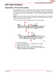
2. Adjust switch to locate plunger pin to 0.8 mm (1/32 in.) between plunger pin and activating
lever assembly.
a
22998
a - 1/32 in. drill bit
3. Slowly move activating lever assembly off until cutout switch opens or closes. Circuit should
open or close when the activating lever assembly is moved 4.8 +/-0.8 mm (3/16 +/- 1/32 in.).
Measure with 152 mm (6 in.) steel rule.
b
a
b
c
22999
a - Cutout switch
b - Movement of activating lever assembly
c - 152 mm (6 in.) steel rule
4. After adjustments are made and are within 4.8 +/-0.8 mm (3/16 +/- 1/32 in.), tighten the screws
on the cutout switch. After tightening screws, recheck the plunger pin position.
CHECKING SWITCH OPERATION
1. Reconnect throttle cable(s), removed earlier.
2. Place boat in water and start engine. Check the following:
a.
Shift into forward and reverse gear, making sure that clutch engages before engine
begins to accelerate.
b.
Accelerate engine in forward and reverse gear to ensure engine does not shut down.
c.
Check that shift cutout switch plunger is centered in notch of shift cutout lever, with drive
unit in forward and reverse gear.
d.
Shifting from IN gear position to neutral, ensure drive unit is in neutral before remote
control shift lever comes to neutral detent position.
90-899907001 JULY 2006
Page 3E-21
21