1
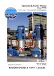
Operation & Service Manual
Pump # 7634
17/21 Axial Flow • Oil Lubricated • Angle Application
Four Stage • PTO Coupled
Technical Services Department
Phone (03) 5874 2101
Fax (03) 5874 2084
Batescrew Pumps & Valves Australia
BATESCREW PUMPS
OPERATION & SERVICE MANUAL
17/21 OIL LUBRICATED
AXIAL FLOW
INDEX
1.
General Layout Drawing
3
2.
Introduction
4
3.
Description
5-7
4.
Assembly and Installation
8 - 12
5.
Operation & Maintenance
12 - 13
6.
Removal, Disassembly and Assembly
14 – 17
7.
Alignments and Tolerances
18
8.
Lubrication Chart and Service Schedule
19
9.
Trouble Shooting
20 - 21
10.
Tools Required
22
11.
Pump Specifications
22
12
Service Records
23 - 24
13.
Warranty
25
14.
Data Sheets and Parts Lists
26 - 28
15.
Component Parts Drawings
29 - 31
2
3
Batescrew Pumps - Operation and Service Manual
2
Introduction
6-Jan-04
Batescrew 17/21 Four Stage Angle application Axial Flow Pump
This pump set is a PTO Coupled, Electrically Driven, Angle Mounted, Irrigation Pump.
The pump set was designed for pumping irrigation water from a river into a channel or
pipe.
Potential Flow Rates 4 stage are up to 10,000 gpm (750 l/s) or Heads to 80 ft. (24 mtrs),
Depending on demand requirements.
SINGLE STAGE CURVE DISPLAYED
4
Batescrew Pumps - Operation and Service Manual
6-Jan-04
3
Description
3.1
Strainer
3.2
Wet End Assembly
3.3
Column Assembly
3.4
Discharge Head
3.5
Drive Extension
3.6
Drive Shaft
3.7
Motor Mount
3.8
Drive Motor
3.9
Discharge Pipe
3.1
Strainer
The strainer serves to protect the impeller and stator from the entry of foreign
bodies.
The design of the strainer is such as to have minimal effect on water flow whilst allowing
the capture of possibly damaging material. All pumps shall be fitted with a protective
strainer. On angle mounted pumps the strainer should be fitted to the intake where it
should be checked for damage and cleaned regularly.
(Note: In such applications it is important that no foreign bodies be allowed to lodge
across the screen and inhibit flow or the pump run without a screen as objects taken in
may cause vibrations and severe damage to the pump).
WARNING Damage to pumps from intake of foreign bodies is not covered by warranty
The pump requires a solid base upon which it may be mounted, preferably at 12’ centres
up the bank i.e.: at each support rail join and a solid slab at the head and knee braces
The supply must be adequate and clear of debris to avoid the impellers running dry at low
water levels.
Typically, a supply coverage of at least 1.5 times the intake diameter would be adequate
however, river conditions can effect this. If in doubt as to the supply characteristics of
your inlet ring Batescrew Technical Assistance for help.
Entrance velocities must be less than 2.5 ft/sec (0.6 m/sec).
5
Batescrew Pumps - Operation and Service Manual
6-Jan-04
3.2
Wet End Assembly
Consisting of four stages, each having 17” diameter Stator, Impeller and Running
Ring also the wet end includes a 17” to 21” Column Adapter, fitted to the bottom will be
a Bell Mouth, sized matched to the pump and including Bottom Bearing. Pump rotation
is provided via the stainless steel drive shaft that is connected to the impellers by taper
lock, locating clip and key.
The shaft and impellers are located in position horizontally by the bottom bearing and
vertically by the top adjusting nut.
The pump impellers are balanced for vibrationless operation and should turn freely (with
no roughness), if vibration or noise during running is encountered the pump may have
been damaged, the factory should be contacted, and repairs made as soon as possible.
Any further damage caused by running a vibrating or damaged pump is not covered by warranty.
3.3
Column Assembly.
The column acts as a pipe line for the flow of water, it is also the support for the
pump and shaft bearings. Shaft bearings are positioned every 4’ (1.2m) along the column
within the lube tube and are lubricated from header tank at a rate of 10 drips per minute
during and for at least 20 minutes before the pump is run.
It is imperative that the oil header tank is never allowed to run dry or be filled with dirty
or non-specified oil; such action may cause serious damage to the pump.
(The only oil recommended is SHELL TELLUS 32 or equivalent grade.)
WARNING: Such action will void warranty
Standard column lengths are 4 ft (1.2m) and 8ft (2.4m) flanged mild steel fully hot
dipped galvanized, the line shaft is high tensile mild steel with a galvanized oil
lubrication tube, lube joiner tubes, and mild steel muff couplings. Shafts and lube tubes
are screwed together in 4ft (1.2m) lengths.
3.4
Discharge Head
Fitted to the top of the column is the Discharge Head unit which acts as the
mounting point for column support, it also contains the top drive shaft, drive extension
mounts. The discharge head unit also turns the water flow through 36 deg so that correct
pipe alignment can be achieved. Usually, mounted to the discharge head is the oil
reservoir that provides the lubrication for the bearings in the pump.
3.5
Drive Extension
The drive extension continues the lube tube and drive shaft from the discharge
head to the thrust bearing mount at a point above flood level, it’s purpose is drive shaft
support and lubrication supply.
3.6
Drive Shaft
The drive shaft attaches to the top of the thrust bearing and connects the top shaft
to the motor shaft.
The drive shaft must be covered with a safety cover by law and removal and operation
without the safety cover is forbidden.
6
Batescrew Pumps - Operation and Service Manual
3
3.7
Description
6-Jan-04
Motor Mount
Motor mounting is achieved by a motor mounting frame which attaches to the
pump mount plate and allows the motor to be attached in line with the pump shaft and
thrust bearing, whilst allowing room for the drive shaft to be fitted and access for shaft
end play adjustment to be performed.
3.8
Drive Motor
The motor is a solid shaft, foot mounted type, selected for the power requirements
of the individual job. The RPM and HP of the motor are matched to the requirements of
the pump at the rate and head required and should only be replaced with a similar motor.
Wiring of the motor must only be done by suitably qualified personnel and correct safety
protection must be fitted.
WARNING: The direction of rotation of the motor is critical and the fitting of a motor of the
wrong rotation will destroy the pump immediately. Always check the motor direction by running
the motor before fitting. No warranty covers damage by reverse rotation.
THE MOTOR DIRECTION MUST BE ESTABLISHED BEFORE CONNECTING
THE PTO SHAFT TO THE MOTOR DRIVE SHAFT.
3.9
Discharge Pipe
The outlet is fitted with a Batescrew standard flange; adapters can be supplied to
change this to any standard flange or seal joint required.
It should be noted that care should be taken in how the water is allowed to leave the
pump outlet, the water should never be allowed to drop directly upon the ground as wash
away will cause soil erosion.
The use of a bubbler or other suitable outlet structure of the appropriate size will
eliminate any erosion and allow unrestricted water release.
7
Batescrew Pumps - Operation and Service Manual
4
Assembly and Installation
4.1
Pre-Installation
4.2
Assembly
4.3
Fit Rail Supports
4.4
Fit Pump
4.5
Testing
6-Jan-04
4.1
Pre-Installation
Before any installation can be performed the site must be prepared.
The Pump will require:
∗
A sound well constructed mounting pad at the top of the bank.
∗
Confirmation of river depth bench mark and flood levels confirming the supply’s
ability to deliver rate required.
∗
Electricity supply at the correct voltage and sufficient amps.
∗
Lifting device or crane to lift pump onto the slide rails.
∗
Site must be accessible with clear workspace.
4.2
Assembly
As a general rule these axial flow lift pumps are shipped from the factory in
sections to facilitate easy assembly, The column support pylons should have been
positioned previously and they should be firm and stable prior to work commencing.
Please take careful note of all warnings and notations.
∗
∗
Refer to the parts break down and check that all parts are present and in good order.
Check that the pump length and diameter is correct and that a clear space of .5 to 0.75
times bell mouth width is achievable from the bell mouth to any objects or riverbank.
4.3
Fit Support Rails
∗ Check that the support pylons have been fitted every 12’ down the bank, starting from
the end of the concrete slab.
∗ A single pylon of substantial enough size and depth may be used and in this
application the rail mount would be a cockie’s perch type with support gussets each
side of upright.
∗ The more traditional support is the single pylon each side system, with a cross rail of
5” channel mounted between the two upright supports via adjusting slide bolts. This
setup gives ease of adjustment, stable support and plenty of adjustment potential.
∗ Fit the pump support into place on the concrete slab, in line with the position of the
pylons, using chemical anchors or Loxin bolts for this job.
8
Batescrew Pumps - Operation and Service Manual
6-Jan-04
4.3
Fit Support Rails
∗ If customer supplied, or some other type of weld-insitue rail support pylons are to be
used, bolt the support rails together, supported with bracing, then weld the cross rails
onto the pylons, making sure of alignment and the 36 deg angle, then refer to the
Pump Fitting section below.
∗ For BATESCREW supplied standard pump supports.
∗ Run two string lines down the bank to give alignment for pylon upright positioning.
∗
The knee braces are bolted to the pump support .
4.3
Fit Support Rails
∗ Install the pump knee brace support base onto the slab, aligned with the desired center
of the pump and orientated to the desired line of the pump down the bank.
∗ Position the first set of upright support rail posts onto the pylons and attach the cross
braces between them, check they are vertical and correctly aligned. When you are
sure the uprights are true, drill the bolt holes and fit the anchors into the pylons.
∗
Bolt the first cross beam support between the first set of support uprights.
∗ Position the second set of support uprights & bolt the next cross bearer between them.
∗ Repeat the procedure until all the support bearers are in place.
∗ Join the slide rails together as you slide them into position on to the cross bearers
down the bank.
∗ The last or top slide rail bolts to the pump knee brace support base that has fishplates
to accept it.
∗ Using a string line and angle indicator, adjust the support cross beams to achieve the
correct angle and straightness of the support rails.
∗ Check all nuts and bolts for correct tension.
∗ Do not fit the top knee braces to the pump support base (If you fit knee braces it will
be in the way when assembling pump)
∗ Install the motor support frame and extension drive support rails, using a string line
and angle indicator to get the correct alignment.
4.4
Fit Pump
∗ The wet end would have been supplied complete including the pump-to-column
adaptor and some column sections, check that this is undamaged and clean.
∗ Using appropriate lifting equipment, lift the main pump assembly (wet end and
attached column sections) from the ground to a position above and in line with the
support rails (make sure the pump is held so that it sits at the correct angle and
rotation for fitting).
∗ Lower the pump assembly until it sits correctly in the support rails and secure it using
a strong lifting device, allow the pump to slide down the rails until the next column
section and lube tubes will fit onto the work position.
∗ Apply liberal amounts of stag paste to the thread of one lube tube joiner and Screw
the lube tube joiner half-way into the top of the lube tube protruding out of the top
column section fitted to the pump.
9
Batescrew Pumps - Operation and Service Manual
4
∗
∗
∗
∗
∗
∗
∗
∗
∗
∗
∗
∗
∗
∗
∗
∗
∗
∗
∗
∗
∗
∗
∗
6-Jan-04
Assembly and Installation
Pump 250m1 of Tellus 32 or 42 oil into the top lube tube to pre lube the pump.
Apply a small amount of never seize to the thread of the line shaft protruding from
the lube tube in the pump and screw a muff coupling half-way onto the line shaft.
Lift the next 8’ section of drive shaft and lube tube from the ground and position at
the correct angle to allow you to screw the line shaft into the muff coupling.
Apply a small amount of never seize to the thread of the line shaft and screw the shaft
into the muff coupling until it bottoms firmly onto the bottom line shaft.
Apply liberal amounts of stag paste to the thread of the lube tube joiner and screw the
suspended tube on to the joiner until it firmly butts against the bottom lube tube.
Using an appropriate lifting sling, pick up the next column section and slide it along
the rails, over the lube tube/Lineshaft, until it butts against the existing top column
(make sure the spider mount web inside the column does not entangle the lube tube as
it is fitted, this is best achieved by making sure the spider is positioned to the topmost
point and the natural droop of the lube tube will allow the correct entry).
Rotate the new column 180 degrees and fit the column flange bolts and nuts.
Fit the lube tube clamp saddle and two bolts and nuts with lock nuts.
Lower the pump assembly until the correct workstation is once again achieved.
Repeat all the steps again until all column sections are installed.
WARNING Do not forget to install 250 ml of oil into every lube tube, as pump
seizure may result if not done.
Fit the next section of lube tube and line shaft
Using a suitable lifting sling lift the discharge head so that it sits at the correct angle
and slide it over the lube tube until it is positioned against the top column, bolt it into
place.
Align the knee braces with the rails, and by moving the pump or braces, align the
rails/pump/slab correctly using the multiple choice holes built into the head and knee
braces.
(If alignment is not correct, bolt holes in the knee braces may need to be reselected
until correct ones are found, remove the slings and fit any additional bracketing.)
Fit the bottom gland plate to the extension mount stool in the head.
Fit the “o” ring seal over the lube tube and slide it down into place against the head
extension sealing flange, smear the sealing flange with stag paste.
Fit the first drive extension outer sleeve over the lube tube and bolt into place.
Assemble the drive extension as you did with the column sections until all drive
extensions, lube tubes and line shafts are fitted do not forget to install lubricant into
lube tube.
Fit the bearing mount to the top drive extension and bolt down.
Install the tension nut to the top of the lube tube using stag paste to seal the joint,
tighten firmly and bolt to the bearing mount.
Coat the tension nut lip seal with lubricant and carefully install it into the tension nut.
Install the last muff coupling and the top shaft
10
Batescrew Pumps - Operation and Service Manual
4
∗
∗
∗
∗
∗
∗
∗
∗
∗
∗
∗
∗
∗
∗
∗
∗
∗
∗
∗
∗
∗
6-Jan-04
Assembly and Installation
Install the extension drive mount plates to the motor mount tower.
Fit the bearing mount stool and install the thrust bearing assembly.
Align the slot in the thrust bearing hollow shaft with the keyway in the top shaft and
install the drive key (make sure the drive key is firm but not binding as the shaft will
need to slide so the correct top nut adjustment will be achieved).
Install the motor to the motor mount frame, aligning it with the thrust bearing.
Install the bottom half coupling and slide it down the shaft clear of the top nut area.
Fit the top nut, being sure the locking screws are backed out (not fouling the thread).
Screw the top nut down against the thrust-bearing boss, pulling the line shaft up until
the nut firms up and the pump can be felt to seize as the impeller touches the stator.
Back the top nut off 1.5 turns so that the impeller clears the stator.
If the top nut runs out of thread call BATESCREW for help.
If the line shaft does not drop as the top nut is backed off then the key way is most
likely too tight or the line shaft is seizing at some point (repair and retry).
When the top nut is correctly adjusted the pump should turn smoothly.
Tighten the top nut locking screw (onto the keyway only).
Install the top PTO drive coupling to the drive shaft on the motor
Install the PTO shaft safety cover bottom half to the mount frame
Install the PTO shaft to the thrust-bearing end only, using the high tensile bolts.
Make sure that PTO is not in connected to the drive motor until motor rotation has
been established. (Follow the directional arrow on pump).
Install the oil tank and connect the oil lines to the tension nut with the fittings
provided
The line connectors are fitted each side of the tension nut, one supplies oil the the
lube tubes and one gives vapor return from the oil cavity (it does not matter which
fitting is on which hole unless one hole is higher than the other then the vapor line is
to the highest hole.
Set the adjustable dripper that is installed at the oil discharge line from the bottom of
the tank to 10 drips per second at least 1/2 hour before starting the pump. (The
dripper must be supplying oil, if the line fills then check for blocked lines or vapor
lock, it may be necessity for the pump to be turned over in order to start the dripper
working).
Run the drive motor uncoupled from the PTO and make sure that the direction of
rotation is correct.
Only when you are sure that the rotation is correct, slide the PTO couplings into
place, fit the bolts, and then install the PTO shaft safety cover top half.
NOTE: It is the responsibility of the installer to check motor direction prior to installation
Failure to do so may cause severe pump or motor damage thus voiding warranty.
∗ Fit the discharge pipe and gaskets
Install any concrete anchors making sure all mounts are sitting flat.
11
Batescrew Pumps - Operation and Service Manual
4
6-Jan-04
Assembly and Installation
4.5
Testing
∗ Check by hand that the pump turns freely with no noise or roughness.
∗ Check that all persons and animals are clear of the pump and that all safety devices
are connected and in place, especially all intake guards and covers. Make sure all
inlet and out let valves are open.
∗ Run the pump for 15 seconds and check for smooth operation and lack of noise.
∗ Check oil is running down the lubrication line (check dripper is clear and running)
∗ Check for excess temperature at tension nut.
∗ Check all bolts and connections and restart the pump for 5 minutes.
∗ If all is still well then turn pump over by hand and test for freeness and lack of noise.
∗ Check the pump at regular intervals for leaks or noises.
∗ Check and note motor amperage, volts, power factor, and river level at time of test.
5
Operation
5.1
Start-Up
∗ Always check safety covers are fitted, especially intake screens and electrical covers.
∗ Check all personnel and animals are clear of intakes and outlets including channels.
∗ Carry out service procedures as outlined in maintenance.
∗ Fill lubrication oil tank and start oil lubrication at 10 drops per minute at least 15
minutes before the pump in needed.
∗ Open the intake and outlet valves.
∗ Ensure that water is present.
∗ Turn on mains, check for electrical problems, (live components, bypassed fuses etc.)
∗ Start the motor and listen/feel for any unusual noises or vibrations.
∗ Adjust the flow with directional gate valves, if fitted.
∗ Check that seal leaks take up, if not, find the cause of leakage and adjust or repair.
∗ Safely secure the pump site (especially from children)
5.2
During Operation
∗ Check the pump every couple of hours for unusual noises or vibrations.
∗ Check the intake screen area for build up of foreign material at least twice a day.
∗ Watch for seal leakage and adjust/repair if needed.
∗ Check oil lubrication rate, adjust to 10 drops per minute if needed, fill oil tank as
needed with clean SHELL TELLUS 32, TEXACO 32 or equivalent oil.
∗ On systems running continuously, grease bearings once a week (two pumps of
SHELL ALVANIA EP3, MOBIL,TEXACO ALVANIA EP3 grease).
∗ Check motor temperature regularly to assure motor is not overloading and
overheating.
∗ Check the tension nut for temperature and note motor amp draw.
12
Batescrew Pumps - Operation and Service Manual
5
6-Jan-04
Operation
5.3
Shut Down
∗ Turn off motor and isolate all electrical circuits.
∗ Shut all inlet and outlet gates.
∗ One minute after pump has stopped turning, close down lubrication oil flow.
∗ If bearings have not been greased then grease nipples whilst they are warm.
∗ Clean and secure site.
∗ Note any defects and have them fixed whilst pump is idle.
∗ Fill out pump user’s register.
This operation direction outlines the suggested way to manually start, run, and close
down your pump set.
It by no means covers every application and every eventuality.
Auto operation is not covered in this manual and correct operation of auto start stop and
run pump stations must be set by the controller manufacturer/installer, bearing in mind
the needs for protecting these pumps from running dry or out of lubrication.
If problems occur in start up or running of your pump set call Batescrew Technical
Department for help.
Whilst Batescrew design and build these pumps with performance and safety in mind, it
is solely the responsibility of the operator to always maintain & operate the equipment in
a safe and appropriate manner, bearing in mind today'
s ever changing occupational and
health requirements.
Special care must be taken in relation to appropriate safety covers on all
moving parts.
13
Batescrew Pumps - Operation and Service Manual
6
6-Jan-04
Removal, Disassembly, and Assembly
6.1
Disassembly
The disassembly of the pump may be for any number of reasons. It is assumed here that
disassembly is for impeller replacement.
∗
∗
∗
∗
∗
∗
∗
∗
∗
∗
∗
∗
∗
∗
∗
∗
∗
∗
∗
∗
Note the direction of rotation of the pump (VERY IMPORTANT).
Disassemble the pump in the reverse procedure as for assembly, as described earlier
in this manual, until the drive extension has been removed.
Unscrew the bolts securing the head to extension drive seal plate, then remove the
seal plate and “o” ring seal.
Disconnect the discharge pipe and remove it.
Using a block and tackle plus a securing chain, or similar devices, secure the pump
from sliding whilst allowing the pump to be slid upwards to gain access to all parts.
Remove the two bolts attaching the head to the knee braces.
Remove the column / head securing bolts
Slide the head assembly upwards until access is gained to the first lube tube joiner.
Unscrew the top lube tube from the joiner, slide the lube tube up to expose the first
muff coupling.
Unscrew the top line shaft out of the muff coupling, If you are unable to unscrew a
coupling, strike opposite sides of the coupling at the same time with two 2kg
hammers. (This loosens the coupling on the shaft, stretching the thread and, provided
excessive damage is not done, the coupling may be reused. If in doubt replace the
stretched coupling.) Unscrew the muff coupling from the lower line shaft.
Remove the head assembly.
Remove the lube tube joiner from the lower lube tube
Lift the pump up the rails and support underneath the first column flange.
Unscrew the top shaft muff coupling.
Remove the lube tube clamp bolts and remove the half clamp.
Clean the stag jointing compound from the surface of the lube tubes and joiners and
remove the lube tube, line shaft.
Remove the column bolts at next column to be removed and remove the column,
exposing the next two lube tubes.
Unscrew the next lube tube at the joiner and remove it
Remove the lube tube joiner and then remove the next lube tube exposing the line
shaft muff coupling
Remove the line shaft from the muff coupling and remove the muff coupling and lube
tube joiner
14
Batescrew Pumps - Operation and Service Manual
6
6-Jan-04
Removal, Disassembly, and Assembly
6.1
Disassembly
∗ Remove the lube tube clamp bolts and remove the half clamp.
∗ Remove the next column and repeat the above procedure until all column sections
and lube tubes have been removed.
∗ Lift the wet end out of the rails and away to a stable and clean workspace.
∗ Prepare the wet end for transport or rebuilding.
∗ Clean and protect all column ends and registers.
∗ Check exposed bearing clearances and if needed open every column joint and
remove, open every lube tube to check bearings and shafts. (This is advised as worn
bearings will cause vibration and breakage problems later).
∗ It is strongly advised that the wet end be returned to the factory for repair or
replacement, any worn components be replaced with the original equipment only.
∗
∗
∗
6.2
∗
∗
∗
∗
Check column sections for corrosion and machined flanges for distortion or damage. Clean all
reusable columns, pay special attention to the mating faces and registers.
Inspect drive shafts for wear and corrosion. If corrosion is severe, replace only with genuine
BATESCREW parts that are correctly end machined for true alignment.
Check all bolts and nuts removed from the pump and replace any showing wear.
Disassembly of Wet End Assembly.
IT IS RECOMMENDED THIS BE DONE BY BATESCREW
Remove any lube tubes, shafts and grease line fittings that may still be attached.
Remove the stator to column adapter bolts and remove the column adaptor.
Remove the top stator to running ring bolts and remove the top stator, exposing the
top impeller and impeller shaft ready to measure.
Attachment of the impeller to the shaft is by taper lock, with bolt on retaining plate.
(The position of the top impeller on the shaft must be noted. Measure from the top
(threaded end) of the shaft to the impeller face and also the taper lock face).
∗
∗
∗
∗
∗
∗
∗
∗
Remove the intake bell to bottom running ring bolts and slide the intake from wetend.
Unscrew stainless steel bolts attaching the taper lock plate to the impeller and remove
the taper lock plate from the bottom impeller.
Whilst protecting its end and thread, rest the top end of the impeller shaft on a solid
surface. Being careful not to damage the impeller, give the impeller a swift blow
from below. This will shock the impeller from the taper, allowing its removal.
Remove the taper from the shaft
Remove the impeller from the wet end
Remove running ring to stator bolts and remove the running ring from the wet end.
Remove the stator to second running ring bolts and slide the stator from the shaft,
exposing the next impeller and locking plate.
Repeat the procedure until all impellers and running rings have been removed.
15
Batescrew Pumps - Operation and Service Manual
6
6.3
∗
∗
∗
∗
∗
6-Jan-04
Removal, Disassembly and Assembly
Assemble Wet End
Clean and inspect all parts, replace anything that looks suspect, check shafts and
bushes for wear, (If in doubt contact Batescrew Technical Service Department Ph
0358742101 or FAX 0358742084 for correct advice.
Do not use non-original or modified parts, as quality and performance may suffer.
INSIST on only repairing with BATESCREW original pump parts.
BATESCREW stock most components for there pumps, these can be supplied upon
demand through your local irrigation agent or direct from BATESCREW SALES.
Do not return defective or worn parts into service as failure may cause severe damage
to other pump components.
Assemble Wet End
∗ The correct position of the impeller on the shaft must have been established during
disassembly, if this was not done contact BATESCREW for help.
∗ Install the top impeller taper on to the shaft at the location measured during
disassembly (large end away from the threaded end of the shaft).
∗ Slide the impeller onto the taper and fit the taper locking plate.
∗ Install and tighten the locking plate bolts evenly, securing impeller the shaft, checking
that the dimension from end of the shaft to the taper has not changed.
∗ Install the top running ring onto the top stator.
∗ Slide the shaft and impeller into the stator/running ring assembly.
∗ Fit the second stator to the top running ring and bolt into place.
∗ Lock the impeller shaft so that the top impeller is up, firm against the top stator.
∗ Slide the impeller onto the shaft, firm up against the second stator assembly.
∗ Install the taper to the shaft and up into the impeller.
∗ Fit the second impeller locking plate and bolts but do not tighten them yet.
∗ Making sure that both the top and second impellers are firm against their stators, thus
locating them onto the shaft at the correct spacing, tighten the locking plate bolts.
∗ Install the second running ring and the third stator.
Check after each impeller is fitted that end float has not been diminished, indicating
correct impeller placement on the shaft.
∗
∗
∗
∗
∗
Repeat the above until all impellers and running rings have been fitted.
Install the intake bell to the bottom running ring.
Check clearance of the shaft in the bushes and Lip seals, replace if necessary. For
wear limits and clearances refer to TOLERANCES section of this manual.
Check impeller tip to running ring clearance (max. allowed is 3mm overall).
Check the list in this manual, to be sure you have the correct lubricants and sealant
ready.
16
Batescrew Pumps - Operation and Service Manual
6
6-Jan-04
Removal, Disassembly, and Assembly
6.4
Reassemble Pump
∗ Reverse procedure used to dissemble the pump, then follow assembly section #4.
∗ Make sure all lubrication tubes are tight. Test shafts on “V” blocks to check for
straightness.
∗ Make sure you assemble the lube tube joiner/bearings equally onto each tube.
∗ Muff couplings must be screwed equally onto each line shaft, the machined shaft ends
must be touching each other in the muff couplings, so that correct alignment is
maintained, if this is not done vibrations and early pump failure will result.
∗ Check each shaft for bends, wear, corrosion, damage to machined ends or threads.
∗ Only replace shafts with Original parts that are machined to fine tolerances, the use of
incorrectly finished shafts will destroy the pump and may cause irreparable damage.
∗ Use the correct lubrication and sealants from the list in this manual as you assemble.
∗ Fill every lube tube with 250 ml SHELL TELLUS 32 or equivalent oil as you
assemble them.
∗ Align all parts to the specifications given in the table in this manual.
∗ Check after each stage for signs of tightness or roughness that would indicate
incorrect alignment or faulty assembly.
∗ Adjust the top nut to the original position, if the pump is loading up adjust a further
one turn, if this does not give correct Impeller positioning you may have not aligned
the impeller back onto the shaft in the correct position. You may need to dismantle
the pump to correct this. For help ring Batescrew Technical Department
Before reconnecting the drive, always check the direction of rotation is correct, as
stated in original installation. A drive turning in the wrong direction will destroy
your pump. Always check, even if you believe it has not been altered. Just in case!
17
Batescrew Pumps - Operation and Service Manual
7.
6-Jan-04
Alignment and Positioning Data
Alignment and Positioning
NOTES
Column to flange alignment:
Align O.D. of each flange with 150mm ruler on the
outside of the flange in 4 positions.
Lube tube to lube tube:
Must butt up tight and evenly spaced.
Shaft to shaft in joiners:
Must butt up tight and evenly spaced in joiner.
When assembling:
Rotate shaft after each component is attached, to
ensure correct alignment.
Shaft inside lube tube:
Must be in the centre at all times, if not, look for a
bent shaft, lubricant between shafts/joiner, nonoriginal or damaged shafts.
Straightness of shafts:
Shafts set on V blocks and checked for straightness,
0.003” per 4ft (0.07mm per 1200mm).
Bush clearance on shaft:
0.003” per 1” of diameter, plus 0.004”.
7. Tolerances
PART NAME
TOLERANCE
LIP SEAL
TOP ROLLER BEARING
Ref. skf
BOTTOM ROLLER BEARING
Ref. skf
TENSION NUT LIP SEAL
-1.5 mm
TENSION NUT BUSH
0.15 mm
LUBE TUBE JOINER BUSH
0.15 mm
LUBE TUBE ADAPTER BUSH
0.15 mm
STATOR BUSH
0.15 mm
STATOR LIP SEAL
0.15 mm
THROTTLING BUSH
0.15 mm
BELL MOUTH BUSH
0.15 mm
IMPELLER to R/R.RING
3.00 mm
18
Batescrew Pumps - Operation and Service Manual
8.
6-Jan-04
Lubrication chart Recommended Oils and Greases
PART
LUBRICANT
Oil lubrication tank:
Shell Tellus 32 or equivalent.
Grease nipples:
Shell Alvania EP3 or equivalent.
Special Fittings.
Service Schedule
Clean motor cooling fins and air intakes:
Every 30 days in std conditions and every 7
days in severe conditions.
Fill oil tank:
Every day if running continuously, or 15
minutes before start on intermittent use.
Grease nipples:
Once a week continuous running, once a
month on intermittent, 2 pumps only in each.
Check drive shaft coupling:
Once a month.
Check attaching nuts and bolts:
Once a month.
Check pump for vibrations, noise etc:
Twice a day on continuous use or every start
up on intermittent use.
Check inlet screen:
Daily.
Check wiring and lines:
Every start up.
Position
Lubricant / Sealant
On the shaft inside bush:
Smear of TEFLON grease.
On the shaft inside lip seal:
SILICON grease.
On bolts & inside nuts:
COPPER based grease.
Between grease line fittings:
TEFLON tape or paste.
Between flange faces:
Mix 1/2 multigrade oil & black TAR paint.
On shaft inside couplings:
COPPER based grease.
On lube tube joints:
STAG jointing compound or TEFLON paste.
On shaft inside thrust bearing:
COPPER based grease.
On tension nut face to head:
STAG jointing compound.
On oil line fittings:.
TEFLON tape or paste
19
Batescrew Pumps - Operation and Service Manual
9.
6-Jan-04
Trouble Shooting
Pumpset is hard to turn.
Cause
Top shaft nut not properly adjusted:
Lineshaft bearing not lubricated:
Line shaft bent:
Sand blocking impeller assembly:
Misalignment in pump:
Water in oil tank:
Gland too tight:
Object inside pump jamming impeller:
Discharge head not bolted square to column
Misaligned thrust bearing, gland or tension
nut:
Pumpset vibrations
Cause
Drive coupling misaligned or damaged:
Drive motor or mounting bolt loose:
Motor mount misaligned:
Motor out of balance:
Impeller damaged or fouled:
Damaged or worn line shaft bearings:
Strainer partially blocked:
Vortexing water flow entering pump:
Insufficient submergence:
Pumpset worn out:
Motor bearing failure:
Foundation not sufficient under pumpset:
Remedy
Refer to Batescrew.
Check adequate oil flow from drip feeder.
Remove and repair or replace.
Remove and clear sand.
Remove and refer to ‘Overhaul’ section.
Pump seal failure refer to ‘Overhaul’ section,
condensation in tank.
Adjust.
Remove and repair or replace.
Adjust or clean and re-align.
Adjust or clean and re-align.
Remedy
Realign or replace.
Tighten or replace.
Realign mount or replace
Repair motor, check for vermin in motor.
Remove pump and repair/replace or clear.
Remove pump and repair.
Clean or repair.
Reduce speed to see if it stops:
Install in a deeper sump.
Remove, refer to ‘Overhaul’ section.
Repair motor, check lubrication.
Remove and reinstall correctly.
20
Batescrew Pumps - Operation and Service Manual
9.
6-Jan-04
Trouble Shooting
Pump is producing insufficient or varying flow rates.
Cause
Strainer blocked:
Pump starving for water:
Submerged eddy currents:
Drive coupling failure:
Motor seizing:
Broken line shaft:
Muff Coupling disconnected:
Motor speed too slow (one phase failure):
Static water level has dropped:
Impeller loose on shaft:
Discharge line closed or blocked:
Column holed or blocked:
Impeller or stator damaged or worn:
Excessive head:
Density or quality of pumped material poor:
21
Remedy
Remove pumpset and clear strainer.
Provide more submergence for pump.
Ensure more even flow to pumpset.
Replace coupling, check alignment.
Repair motor, check for rubbish at inlet.
Remove and repair.
Remove and replace/repair (check D.O.R.)
Replace motor or check supply (fuses).
Repair/deepen sump.
Remove and replace/repair.
Open valve or clear obstruction.
Remove and replace/repair.
Remove and replace/repair.
Check discharge head , refer specifications.
Check supply cleanliness.
Batescrew Pumps - Operation and Service Manual
10.
6-Jan-04
Tools
Although no special tools are needed, some operations are easier and safer with
appropriate tools.
∗ Impeller slide hammer
This is a machined slide that fits over the impeller shaft and is used to insert and release
taper sleeves in impellers. Accurate impeller positioning can be difficult without this tool
and an impeller is easily damaged when removed by any other means.
Other Tools that may be required
∗ Stillson wrench 18” ( 2 sets ).
∗ Medium size podger bar.
∗ Feeler gauge set.
∗ Set square.
∗ 2 only 5lb engineers hammers.
∗ Hook wrench 32-76 mm.
∗ Screw drivers.
∗ Fine cut file.
∗ Cleaner and cloth.
∗ Vee Blocks and dial gauge.
11.
*
*
*
*
*
*
*
*
*
*
Medium size brass hammer.
Imperial and metric Allen key sets.
Spirit level.
Vernier and measuring tapes
String line.
Socket sets metric.
Imperial and metric ring spanners.
Emery cloth.
Lifting jib or crane.
Chain tongs.
Pump Specifications
PUMP TYPE
AXIAL
PUMP SERIAL #
MOUNT TYPE
ANGLE
DRIVE TYPE
MOTOR TYPE
Client
supplied
MOTOR HP
RATING
250 HP
MOTOR (DIR.)
C/W
7634
PUMP SIZE
17/21
DIRECT
COUPLED
DESIGNED FLOW
10100gpm
MOTOR SERIAL #
Client
supplied
DESIGNED HEAD
52ft TOTAL
PRODUCTION DATE
08/2003
DESIGNED RPM
INSTALLATION
DATE
22
2003
DESIGNED HP
1470
200 HP
BATESCREW PUMPS AND VALVES SERVICE HISTORY. PUMP #
7634
DATE INSTALLED
12. Service Records Log
DATE
MOTOR
HRS
COOLING
FINS
CLEANED
DRIVE
COUPLING
CHECKED
INTAKE
STRAINER
CLEANED
PUMP
VIBRATION
CHECK
23
BOTTOM
BEARING
GREASED
TOP
BEARINGS
GREASED
GLAND
CHECK
COMMENT
BATESCREW PUMPS AND VALVES SERVICE HISTORY. PUMP #
7634
DATE INSTALLED
12. Service Records Log
DATE
MOTOR
HRS
COOLING
FINS
CLEANED
DRIVE
COUPLING
CHECKED
INTAKE
STRAINER
CLEANED
PUMP
VIBRATION
CHECK
24
BOTTOM
BEARING
GREASED
TOP
BEARINGS
GREASED
GLAND
CHECK
COMMENT
Batescrew Pumps - Operation and Service Manual
13.
6-Jan-04
WARRANTY
The Company undertake that the goods manufactured by the Company shall be
of first class materials and of sound workmanship, and that the company will make good
or replace any defective parts therein, which under proper use, may appear within six
months of dispatch from the company’s works, and which have proven to be due solely to
the use of defective materials or bad workmanship.
Provided always that such parts are promptly returned free to the company’s works
unless otherwise arranged and any defective parts to the Company’s property.
The repaired or new parts will be returned to the site.
Any goods not of the Company’s manufacture, included in this tender, are sold under
such warranty only as the makers give us, and we are able without legal expense to
enforce, but are not guaranteed by us in any way whatsoever.
The warranty does not cover malfunction resulting from misuse, negligence, alterations,
accident, or lack of performance of normal maintenance service, loss of time,
inconvenience, loss of use of equipment, or other consequential damages.
The warranty does not exclude any condition, or warranty implied by the trade practices
act. 1974, or any state legislation, but in all other respects, the warranty is in lieu of other
warranties, expressed or implied, and all other obligations or liabilities. No promise,
representation, or statement, by any employee, representative, or agent of the Company,
or by any other person, shall add to, vary, or modify this warranty, or give use to any
obligation on the part of the company.
Further, no promise, representation, or statement by any employee, representative, or
agent of the Company, relating to the suitability of the equipment for any purpose shall
bind the company or give rise to any obligation on the behalf of the Company.
25
Batescrew Pumps - Operation and Service Manual
14. Data Sheets And Parts Lists
6-Jan-04
PUMP REC ORD SHEET.
C LIENT:
Cave & Weier
a/c The B auhinias
PHONE NO: 0749842600
DATE
PUMP SIZE:
JOB NO:
QUOTE NO:
07/08/2003 PUMP,NO: 7634
17/214sta o/l 56:36d/c pto e
5628
D D5023
FAX NO:
ORDER NO:
22259
0749842522
ADD RESS: 4 D aniel st , Emerald
D ELIVERY AD DRESS tobe arranged
C ARRIER & DETAILS:
C ONSIGNMENT NO:
D ATE OF D ELIVERY:
13/09/2003 SOLD BY:
AC C NO
DATE ORDER
17/07/2003
C ARRIER NO:
AGENT:
DD
ANGLE APPLICATION
ROTATION C W
ELECTRIC
DIREC T C OUPLED/PTO 10100gpmat52.4ft 200 hp
NO OF STAGES
4
IMPELLER; 17-21-8 1/2
TRIM:
Full
STRAINER
yes
TYPE
basket+plate
LOCKING PLATE
yes
B.B.H. LUBRICATION
grease
TOP STATOR LUBE
oil
COLUMNS
21" gal 8ft clamp 88.9 7 off
Inter stator lube
grease
EXTENSION C OLUMN
14" gal clamp 88.9 4of + 1 of 4 ft ?
HEAD
21" *36 degree oil
MOUNT PLATE
knee braces
IMPELLER SHAFT
1 3/4" x 64"
THREAD SIZE
1 3/4" nf rh
LINESHAFT
1 3/4" 1040 grade 96" long 11 off
INTERMED IATE TOP SHAFT
1 3/4" 431 S/S x Len R eqR eq x 1170
TOP SHAFT
2" 431 S/S x Len R eq
x 450
key 200 long top th200 80
MUFF C OUPLINGS
1 3/4" nf rh x 14
CENTRE BEARING HOLD ERS
21" clamp 88.9
NUMBER
7of 21"+4of 14"
BOTTOM LUBE TUBE
3" gal *54" m/fm
48"fm/fm
LUBRICATION TUBE
3nb 88.9 od *48" gal 22 off
TOP LUBE TUBE
3" x 1235
LUBE TUBE JOINERS
3" x 1-3/4" x 23
TENSION NUT
C 4TN 3"* 1 3/4"
GLAND
O ring+2plates
THRUST BEARING
N o5
WATER C OLLED
OIL TANK & FITTINGS
1 gallon set
LTJ
3"*1 3/4 " 23 off
D ISCH ARGE PIPE
FLANGE PUMP END
FLANGE PIPE END
LENGTH
ANGLE
MATERIAL
PAINT
GASKET & BOLTS SET
SPARE FLANGE & PIPE O.D.
H AR DY SPICER DR IVESH AFT
SERIES
GWB687-40
C OMPRESSED LENGHT30"
EXTEND ED LENGTH
32"
ADAPTOR S
PTO DRIVE COUPLING BORE D IAM
? REG
KEY WAY WIDTH
DEPTH
PTO DRIVEN C OUPLING BORE DIAM2 3/4"
REG
KEY WAY WIDTH
1/2"
DEPTH
1/4"
ELECTRIC MOTOR (client to supply )
MAKE
HP
SPEED
FOOT MOUNTED
FLANGE MOUNTED
notes:
grease lines on RH S
correction bend
double gibopipe
inline non return valve + 6" outlet for PRV V/N 3394
Bermad 6" pressure relief valve setting = 6.1Mts
tension nut mount 14" diameter
discharge pipe adaptor to 700 table D
pto guard
knee braces
Slide Rail spacing 15"
Modify screen and Bellmouth to suit slide rails
support from bottom rring to slide rails to suit 21"column
26
NO HOLES & D IAM
NO HOLES & D IAM
PTO GUARD
FRAME
yes
Batescrew Pumps - Operation and Service Manual
6-Jan-04
BATESCREW PUMPS RECORD SHEET
Cave & Weier
PUMP NO 7634
DATE
17/214sta o/l 56:36d/c ptoJOB
e NO:
07-Aug-03
5628
NUMBER
DESCRIPTION
SIZE
NO OF
17-1-S
INLET SCREEN
17" S/S MESH 477 long
1
12
12mm35G
17-3-5
17-3-7
LS0-17
17-3-9
BOLTS & NUTS (IS/BBH)
B.B.H. A2(G.L.)
LB2 BUSH (G.L.)
LIPSEAL G/L (s.s spring)
BBH GREASE TUBE (G.L.)
12mm x 35mm GAL
17" A2 B.B.H.-G/L
LB2 1-3/4"x2-1/4"x3"
1-3/4"x2-1/4"x3/8"
15NB S/S x 235 MM
4
1
1
1
1
0.2
69
0.72
0.05
38FGLSF FLEXIBLE G/L with S/S Fittings
16mm55G BOLTS & NUTS (BBH/RR)
17218A2
IMPELLER 17-21-8 1/2
17-7-1
TAPER SLEEVE
17-7-3
LOCKING PLATE
12mm50SS IMPELLER BOLTS
17-7-7
SLINGER PLATE
17-6-2
RUNNING RING (S.S.)
16mm55G BOLTS & NUTS (RR/ST)
17-8-4
STATOR A2 (G.L.)
17-8-4-7
BUSH (G.L.)
LS0-17
LIPSEAL G/L (s.s spring)
17-8-15
STATOR GREASE LINE(G.L.)
3838SN
NIPPLE
38FGLSF FLEXIBLE G/L with S/S Fittings
17-8-6
A2 STATOR (O/L)
17-8-13
SEAL PLATE (A2 )
17-8-14
GRUBSCREW (A2 ONLY)
17-8-TB
THROTTLING BUSH
LS0-17
LIP SEALS (0/L)
17-8-6-9
STATOR BUSH (O.L.) A2
12mm40SH S/HEAD C/SCREW(A2 )
17-8-6-14 L.T.ADAPTOR (O.L.)
17-8-6-15 L.T.A. BUSH (O.L.)
17-8-16
STATOR P/BREAK TUBE
13442134R IMPELLER SHAFT (4STAGE)
16mm55G BOLTS & NUTS (STA/ADP)
17-21A
ADAPTOR 17/21
16mm55G BOLTS & NUTS (ADP/COL)
21-17-8
COLUMN 8 FT x 21"
16mm55G NUTS & BOLTS COL/COL
300LT54MF BOT/LUBE TUBE COL/PUMP
3/8 R/H & S/S FITT
16mm x 55mm GAL
17"A2 17-21-8-1/2
1-3/4" (C.I)
17" LOCK/PLATE
12mm x 50mm 304S.S.
17" SLING/PLATE
17" S.S. R/R FAB
16mm x 55mm GAL
17"STATOR G/L
LB2 1-3/4"x2-1/4"x2-3/4"
1-3/4"x2-1/4"x3/8"
15NB S/S x 235 MM
3/8 HEX NIPPLE S.S.
3/8 R/H & S/S FITT
17" A2 O/L
17" M.S.
10mm x 45mmcsk
LB2 1-3/4"x2-1/4"x1-1/2"
1-3/4"x2-1/4"x3/8"
1-3/4"x2-1/4"x4"RHscr
12mm x 40mm S/H-C/S
17" L.T.A x 2-1/2 L/T
1-3/4"x2-1/4"x6"LB2
15NB S/S x 235 MM
1-3/4"SS x 62"x1-3/4R
4" x 1-3/4R
16mm x 55mmGAL
17"-21" ADP (C.I)
16mm x 55mm GAL
21"x96" CLAMP GAL
16mm x 55mm GAL
3" GAL X 48 FM X FM
1
16
4
4
4
24
4
4
112
3
6
6
3
3
3
1
1
2
1
2
1
6
1
1
1
1
16
1
16
7
96
1
0.2
0.4
60
2.4
10
2
8.8
112
4
195
1.98
0.3
0.6
1
1.5
65
2
0.05
0.4
0.05
0.9
0.5
20
1.44
0.2
13
1
42
1
1624
9.1
23.1
300LT48FF
300J134LS
1
2
16mm55G
300TTFM
134MCR12
134MS96R
21-25-2
3
4
5
12mm65G
6
14-17-8
12mm65G
12mm45G
3"GAL x 48" F/M x F/M
3"tube x 1-3/4"shaft
1-3/4"S/SDia x Len Req
2"S/SDia x Len Req
16mm x 55mm GAL
3"GAL Len to suit
1 3/4" RH M.S.
1-3/4"1040 x 96"RH
21"x36 DEG GAL
6 mm diameter 3 1/2" i.d.
12 mm Jig #0057
12 mm plate jig #oo57
12mm x 65mm GAL
8" reg male to 18" reg female 12mm
14" x96"COL CLAMP 3"
12mm x 65mm GAL
12mm x 45mm GAL
22
23
451
85.1
3"NB GAL L/T x 48" F/M x F/M
LUBE TUBE JOINERS
TOP INTER SHAFT W/L S/S
TOP SHAFT S/S
BOLTS & NUTS ( COL/HEAD)
TOP LUBE TUBE
MUFF COUPLING
LINESHAFT 8 FT O/L 1040m/s
DISCHARGE HEAD 36 DEG
O RING
O RING BOTTOM PLATE
O RING TOP PLATE
NUTS & BOLTS 0 RING PL
HEAD / EXT COL ADAPTOR PLATE
COLUMN 8 FT x 14"
BOLTS & NUTS (H/AP/COL)
BOLTS & NUTS (COL/COL)
27
1
1
16
1
14
11
1
1
1
1
4
1
4
12
48
25
342.7
312
1
0.15
15
520
Batescrew Pumps - Operation and Service Manual
14-17-4
COLUMN 4 FT x 14"
3002TN
TENSION NUT ( 2 PART )
3002N134R NUT ( 2 PART )
LS134TN TENSION NUT LIPSEAL
13 T NUT /STOOL BOLTS
7 TENSION NUT STOOL
10 TOP PLATE
11 PLATE/STOOL BOLTS
12 STOOL/BEARING BOLTS
OT0001
OIL TANK & FITTINGS STD
38GL6MS GR/LINE & FITTINGS S/S
1L0GB
GR/LINE BRACKETS & BOLTS
No5 BEARING ASSEMBLY
5-BH
BEARING HOUSING
5-BC
BEARING CARRIER
LS4BH
TOP LIP SEAL
5-CAP
BEARING CAP
5-6315
TOP BEARING
5-7315
BOTT BEARING
LS4BH
BOTT LIP SEAL
8mm30ZP BOLTS
5-375CS CRUB SCREW
6mmGNS ST/GREASE NIPPLE
012100400 KEY
134TN12NF
TOP NUT&CRUB SCREW B/D
12mm45G BOLTS & NUTS (Bear - Head )
34BPVC
COOLING PIPES
34T12BSP COOLING PIPE ADAPTORS
2230SSHC HOSE CLAMPS STAINLESS
DIRECT DRIVE PARTS
17-75
MOTOR ( CLIENT TO SUPPLY )
14" x 48"COL GAL
4-T/Nx 3"Bate
4-NuTx3"Bx1-3/4"
1-3/4"x2-1/2"x3/8"
SHCS M12 * 30
as per drawing
762 profile drawing
M16 * 70 mm
M12 * 50
4 LITRE
3/8 S/S x 6mtr LEN
FAB M.S 1 LINE
30m * 4
6-Jan-04
1
1
1
1
4
1
1
8
6
1
1
13
No5
No5
75.95.10
No5
6315
7315
75.95.10
5mm x 30mm Z/P
10mm x 10mm
6mm
1/2"1"4"
1-3/4"x12TPI x10mmC/S
12mm x 45mm GAL
3/4" Braided PVCx20" 13 m * 2
No P3 3/4"T x 1/2"BSP
1A 22-30 S/S
1
1
1
1
2
2
1
6
2
1
1
1
6
2
2
4
SGA D355MC6 CMG
1
70
45
35
7.5
13
18.5
7.5
1.6
13
3.2
0.5
1
21-81
21-82
21-83
PTO ADAPTOR (motor)
PTO SHAFT
NUTS & BOLTS (Pto -Agd/Adp)
C.I. 95 mm 25 mm
GWB687-40
1/2" unc * 1 1/2
1
1
8
10
35
21-85
21-86
21-89
PTO ADAPTOR (Bearing)
NUTS & BOLTS (Pto -Mtr/Adp)
PTO GAURD
ANGLE BRACKET
ANG BRACKET / PLATE BOLTS
COMPO BEND
HEAD/ C BEND BOLTS
GASKET
O RING
O RING BOLTS
LOOSE FLANGE
GIBO PIPE
O RING
O RING BOLTS
LOOSE FLANGE
INLINE N. R. V. V/N 3394
ADAPTOR
NRV/ADAPTOR BOLTS
PRESSURE RELIEF VALVE
RELIEF VALVE /NRV BOLTS
KNEE BRACES
KNEE BRACE / HEAD BOLTS
NAMEPLATE
C.I. 2 .750" 1/2" * 1/4"
1/2" unc * 1 1/2
300 i.d.*5mm * 1050 long
as per drawing
M20 * 150 long
21" TB 320:320 c/c 21" TB 4 deg
M20 * 65
21" Table B
20 mm diameter 527 i.d.
M20 * 75 mm
as per drawing
527 o.d. * 1000 long
20 mm diameter 527 i.d.
M20 * 75 mm
as per drawing
21" TB :21" TB inline Gal+legs+PRV
21" TB :700 T D 300 long
M20 * 75 mm
Bermad 150 mm 7 m setting
M16 * 65
21" gal pair
M24 * 50
P/N 7634 J/N 5628 970 RPM
1
8
1
1
4
1
16
1
1
16
1
1
1
16
1
1
1
16
1
8
1
2
1
10
8
9
14
15
16
17
18
19
20
21
22
23
24
25
26
27
28
29
30
31
28
10
20
100
5
5
10
150
5
10
200
100
5
6
5
20
15. Component Parts Drawings
29
30
31