1
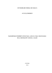
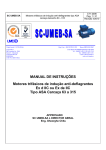
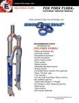
Operation & Service Manual
Pump # 7738
12MS-8 Turbine • Water Lubricated • Vertical Application
Technical Services Department
Phone (03) 5874 2101
Fax (03) 5874 2084
1
Batescrew Pumps &
Valves Australia
INDEX
1.
Component Parts
3-4
2.
Introduction
5
3.
Description
5-7
4.
Assembly and Installation
7-9
5.
Operation & Maintenance
10
6.
Removal, Disassembly and Assembly
7.
Alignment & Tolerances
14
8.
Lubrication Chart and Service Schedule
15
9.
Trouble Shooting
16 - 17
10.
Tools Required
18
11.
Pump Specifications
18
12.
Service Records
19 - 20
13.
Warranty
21
14.
Data Sheets and Pats Lists
22 - 23
15.
Impeller Curve
11 - 13
24
2
1.
COMPONENT
3
2.
Component Parts (wet end)
4
Batescrew 12MS-8 8 Stage Vertical Mounted Pump
3
Description
This pumpset is a DIRECT COUPLED, Vertical Application Pump.
The pumpset was designed for pumping waste water from a pit into an outfall pipeline.
Potential Flow Rates from 50 l/s @ 48mtrs to 120 l/s or Heads to 88mtrs
3.1
Strainer
3.2
Wet End Assembly
3.3
Column Assembly
3.4
Discharge Head
3.5
Mechanical Seal
3.6
Extension Drive (not required)
3.7
Thrust Bearing
3.8
Drive Coupling
3.9
Motor Stool
3.10
Discharge Pipe
3.11
Motor
3.1
Strainer (NO STRAINER SUPPLIED WITH THIS PUMP – BUILT INTO SUMP)
The strainer protects the impeller and stator from entry of foreign bodies.
The design of the strainer should be such as to have minimal effect on water flow whilst
allowing the capture of possibly damaging material (Typically 25mm pass is used).
All pumps should be fitted with a protective strainer. On re-lift pumps the strainer should
generally be fitted to the sump intake. It should be checked for damage and cleaned
regularly.
WARNING: Damage to pumps from intake of foreign bodies is not covered by warranty
The pump requires a solid base upon which it may be mounted and well anchored support
points for the support rails.
The cross rails must be of sufficient cross section to carry the total weight of the pump and
motor when the pump is full of water.
The intake must have adequate supply so as not to allow the pump to run dry.
If in doubt as to the supply characteristics of your inlet line ring Batescrew Technical
Assistance for help.
5
Batescrew Pumps - Operation and Service Manual
3
Description
3.2
Wet End Assembly
Consisting of eight stages, having 12” impeller bowls, impeller shaft, taper lock sleeves,
impellers, inlet bowl with a bottom bearing, and discharge-to-column adaptor.
Rotation is provided via the stainless steel drive shaft connected to impellers by taper lock
sleeves.
(PUMP ROTATION IS ANTI CLOCKWISE)
Shaft and impeller(s) are located in position horizontally by the bottom bearing and
vertically by the top adjusting nut.
Impeller are balanced for vibrationless operation and should turn freely (with no
roughness). If vibration or noise during running is encountered the pump may have been
damaged, the factory should be contacted and repairs made as soon as possible.
Any further damage caused by running a vibrating or damaged pump is not covered by warranty.
3.3
Column Assembly.
The column acts as a pipeline for the flow of water, it is also the support for the pump and
shaft bearings. Shaft bearings are positioned every 4’ (1.2m) along the column and are
lubricated by pumped product.
The pump must never be run dry, as the rubber bush bearings will be destroyed.
Cast Iron columns sections, epoxy coated with two-pack food grade ‘Jotun’, are in lengths
of 4 ft (1.2m), flanged with two pack epoxy coating. Line shaft is stainless steel, joined by
sacrificial mild steel muff couplings.
3.4
Discharge Head
Fitted to the top of the column, the Discharge Head unit acts as the mounting point for
column support, it also contains a machined face for the thrust bearing and motor stool
attachment.
The discharge head turns the water flow through 90 degrees, to align with the discharge
pipe.
Ports for the water-cooled thrust bearing are built into the discharge head.
3.5
Mechanical Seal
This pump is running a tungsten/tungsten/viton mechanical seal
This seal is a long life mining industry standard seal that is preset for life.
The seal may give a small weep when first started but should take up immediately and not
leak when the pump is running.
Seal pressure is achieved by the locking collar positioning on the pump shaft.
Once factory set this should not require any further adjustment.
It is strongly recommended that the seal never be run dry.
6
Batescrew Pumps - Operation and Service Manual
3
Description
3.6
Drive Extension (NO EXTENSION IS REQUIRED FOR THIS PUMP)
The drive extension serves to place drive and mounting some distance above the discharge
head. Drive extension columns are smaller in diameter than pump columns as they do not
handle water flow.
3.7
Thrust Bearing.
Line shaft thrust is carried by the thrust bearing assembly, mounted above the discharge
head.
The thrust bearing is a grease lubricated water-cooled type.
Greasing of the thrust bearing is required every six months. Over greasing causes grease
to issue from the shaft seals and may damage the bearings themselves.
The bearing is designed to run warm (40 to 70 degrees C).
3.8
Drive Coupling
Drive connection between the thrust bearing and the electric motor is via a rubber cross
drive HRC coupling.
This gives quiet, vibration free running whilst allowing for minor misalignments.
No servicing is required of the coupling
Always check the motor direction by running the motor before joining the coupling halves together.
No warranty covers damage by reverse rotation.
THE MOTOR DRIVE DIRECTION MUST BE ESTABLISHED BEFORE
CONNECTING THE COUPLING HALVES TOGETHER.
3.9
MOTOR STOOL
The motor stool is designed to direct couple a flange-mounted motor to the pump
The stool has registers to correctly align the motor shaft to the pump shaft.
3.10 Discharge Pipe
The outlet is fitted with a standard BATESCREW flange.
3.11 Motor
The correct motor for this pump is a 160 kw 4 pole 315-frame flange mounted, suitable for
use with VSD driver.
7
Batescrew Pumps - Operation and Service Manual
4
Assembly and Installation
4.1
Pre-Installation
4.2
Assembly
4.3
Setting the Impeller
4.4
Installation
4.5
Testing
4
Assembly and Installation
4.1
Pre-Installation
Before any installation can be performed the site must be prepared.
∗
∗
∗
∗
∗
The Pump will require:
A sound well constructed mounting pad at the top of the sump.
Two cross rails of sufficient strength for pump support.
Confirmation of inlet ability to supply the flow rate required.
Relevant permits and clearances have been obtained.
Lifting device or crane to lift pump into well.
4.2
Assembly
This pump has been shipped from the factory complete, no assembly is required prior to
installation. The motor has been supplied separately and will need to be fitted.
NOTE: It is the responsibility of the installer to check motor running direction prior to installation;
failure to do so may cause severe pump, thrust bearing and motor damage, thus voiding warranty.
∗
∗
Check that all parts are present and in good order.
Check the pump dimensions, to be sure that pump length from base of the mount plate
to the centerline of the discharge head is correct for the pit.
4.3
Setting the Impeller (This pump has been shipped with the impeller preset)
∗ Ensure that the locking grub screw in the top nut does not interfere with the thread of
the top shaft by backing it completely out.
∗ Tighten the top nut down against the thrust bearing top face, thus raising the drive
shafts and attached impellers (ensure that the drive key is in place in the thrust assy.).
∗ Once the nut has contacted the thrust bearing, continue until the impeller has been
pulled up firm against the stator seal plate in the wet end of the pump. This is indicated
by the pump seizing.
∗ Back off the top nut one full turn, and note that the nut drive shaft drops, lowering the
impellers thus giving wet end clearance again and enabling the pump to turn freely.
∗ The pump should now be free to turn by hand. When the adjustment has been
completed, re-insert the Allen screw into the top nut, making sure that it only seats over
the drive keyway.
8
Batescrew Pumps - Operation and Service Manual
4
Assembly and Installation
4.4
Installation
∗ Using a suitable lifting sling and crane, attach the sling to the discharge head lifting
lugs in a way that allows the pump to hang true when lifted.
∗ Raise the pump, being careful that it hangs correctly.
∗ Lower the pump into the sump until the discharge head is just clear of the support rails.
∗ Insert the four bolts through the head and into the holes in the mount rails.
∗ Lower the pump to sit on the cross rails.
∗ Tighten all bolts and nuts locking the pump into place.
∗ You may now remove the crane and slings.
∗ Attach the discharge pipe work to the pump discharge.
∗ Install the motor half coupling to the drive motor.
∗ Install the rubber drive cross to the pump half coupling on the thrust bearing.
∗ Install the motor to the motor stool, making sure the half couplings are not joined.
∗ Run the drive motor disconnected from the pump to ensure direction of rotation is
correct.
∗ Only when you are sure the direction is correct, slide the two half coupling together.
∗ Make sure water is present in the sump
∗ Check that the discharge is connected correctly and that the delivery point is ready to
accept water.
IT IS RECOMMENDED THAT A NO-FLOW SENSOR BE INSTALLED IN THE
DISCHARGE, TO STOP THE PUMP IN THE EVENT OF NO WATER SUPPLY.
4.5
Testing
∗ Check by hand that the pump turns freely with no noise or roughness.
∗ Check sufficient water supply is available in the sump.
∗ Check that all persons and animals are clear of the pump and that all safety devices are
connected and in place, especially all intake guards and covers, make sure all inlet and
outlet valves are open.
∗ Start the pump and check for correct direction of rotation.
∗ Monitor the pump for noise or vibrations and slowly increase the speed until full speed
is achieved.
∗ Run the pump for 30 seconds and check for smooth operation and lack of noise.
∗ Check all bolts and connections and restart the pump.
∗ Check the pump at regular intervals for leaks or noises.
∗ Fill out pump user’s register.
∗
THIS WARNING IS IMPORTANT
DO NOT RUN THE PUMP WITHOUT WATER AS DAMAGE WILL OCCUR.
9
Batescrew Pumps - Operation and Service Manual
5
Operation
5.1
Start-Up
∗ Safely secure the pump site (especially from children).
∗ Always check that safety covers are fitted.
∗ Check all personnel and animals are clear of intakes and outlets including channels.
∗ Carry out service procedures as outlined in the maintenance section.
∗ Check the WATER SUPPLY level is adequate.
∗ Start the pump.
∗ Check that the pump is pumping correctly.
∗ Monitor pump for noise/vibrations; slowly increase speed until full speed is achieved.
∗ Check that seal leaks take up, if not, find the cause of leakage and readjust or repair.
5.2
During Operation
∗ Check the pump every couple of hours for unusual noises or vibrations.
∗ Watch for seal leakage and adjust/repair if needed.
∗ Grease bearings once a month on systems running continuously.
∗ Check motor temperature regularly to ensure motor is not overloading and overheating.
5.3
Shut Down
∗ Turn the pump off and check that any non return valves have functioned.
∗ Shut all inlet and outlet gates.
∗ If bearings have not been greased then grease nipples whilst they are warm.
∗ Clean and secure site.
∗ Note any defects and have them made good whilst pump is idle.
∗ Fill out pump user’s register.
This operation direction outlines the recommended procedure for starting, run and to close
down your pumpset. It by no means covers every application and every eventuality.
Batescrew design and build pumps with performance and safety in mind but it is solely the
responsibility of the operator to maintain and operate the equipment in a safe and
appropriate manner, bearing in mind today'
s changing occupational health requirements.
10
Batescrew Pumps - Operation and Service Manual
6
Removal, Disassembly and Assembly
The disassembly of the pump may be for any number of purposes, for convenience it is
assumed here that the disassembly is for complete overhaul.
6.1
Disassembly (PUMP REMOVAL)
∗ Remove the DRIVE MOTOR and store it in a safe place.
∗ If the cable length or the pump site will not allow for the motor to be removed with the
cables attached, then call an electrician and have the motor disconnected.
∗ Remove the discharge adaptor bolts at the discharge flange of the head.
∗ Remove the (4) bolts and nuts from discharge head to the mount rails.
∗ Attach secure lifting chains and a crane, with 3 tone capacity at this distance, to the
lifting lugs on the discharge head. Lift the pump vertically out of the pit.
∗ Take the pump to a safe secure location for repair.
∗ Cover the pump hole with a false floor for safety.
6.2
Disassembly (PUMP DISSASEMBLY)
∗ Lay the pump onto a set of pump stands for disassembly.
∗ Mark the motor stool, extension drive stool, discharge head and mount plates, so that
correct orientation can be established when reinstalling them.
∗ Remove the motor stool to head bolts and nuts and remove the motor mount stool.
∗ Note the number of threads protruding from the pump shaft top nut and store the data.
∗ Remove the locking grubscrew and, counting the number of turns, remove the top nut.
∗ Remove the pump half coupling from the thrust bearing and remove the drive key.
∗ Remove the bolts securing the thrust bearing to the head & remove the bearing.
∗ Remove the top shaft and muff coupling. (If you are unable to unscrew a coupling,
strike opposite sides of the coupling at the same time with two 2kg hammers, loosening
the coupling on the shaft.)
∗ Remove bolts holding the seal seat holder to the head and remove the Mech seal.
∗ Remove bolts joining the pump head to the top column and top-bearing carrier.
∗ Remove the discharge head.
∗ Remove the top-bearing carrier from the top column and shaft.
∗ Support the pump under the bottom column and remove the column-to-column bolts
from the two columns, then remove the top column.
∗ Unscrew the line shaft from the muff coupling and remove it and the coupling.
∗ Remove the center-bearing carrier from the column and shaft.
∗ Remove the bolts holding the bottom column to the wet end and remove the bottom
column.
∗ Unscrew the line shaft from the muff coupling and remove the line shaft.
∗ Lift the wetend assembly to a clean workspace.
∗ Clean all parts and disassemble all lube tubes to check bearings.
11
Batescrew Pumps - Operation and Service Manual
6
Removal, Disassembly, and Assembly
6.2
Disassembly of Impeller Assembly.
It is recommended that the wet end rebuild be performed by BATESCREW at the factory.
∗ Impellers are attached to the shaft by taper lock sleeves.
∗ Remove the bolts attaching the inlet bowl to the impeller bowl & remove the intake
bowl.
∗ While supporting the shaft from moving at the top end, use a taper driver (which will fit
inside impeller) to drive the sleeve out of the impeller, working from the bottom..
Note the exact positions of the impeller and sleeve on the shaft, as they must be returned to
these positions when reassembled.
∗
∗
∗
∗
∗
∗
∗
Remove the impeller from the bowl and shaft.
Remove flange bolts between the bottom impeller bowl to second impeller bowl.
Remove the second impeller using the taper driver.
Repeat the process until the wet end is completely disassembled.
Remove all of the impeller bowl bushes and inlet bowl bearings and seals for
replacement.
Clean and inspect all parts, replacing any that looks suspect. Check shafts and bushes
for wear, ( If in doubt contact Batescrew Technical Service Department, phone
0358742101 or fax 0358742084, for correct advice.)
Do not use generic parts, performance may be degraded.
6.3
Assemble wet end
∗ The correct position of the impellers on the impeller shaft is critical to assembly and
must have been noted during disassembly; if not call BATESCREW for help.
∗ Fit the bottom impeller to the impeller shaft at it’s original position, by positioning the
impeller and taper on the shaft at the correct location and then, using a slide type driver,
drive the taper into the impeller, locking both to the shaft.
Be careful that the bottom impeller is positioned correctly on the shaft.
∗ Fit the new bushes and seals to the stator and intake bell (bottom bearing holder).
∗ Apply rubber grease to the bowl and intake bearings for initial lubrication.
∗ Sit the intake bowl on a solid surface, intake down, then place the impeller and shaft
into the bowl, with a spacer in the intake bush to support the shaft so that the impeller is
sitting just clear of the intake bowl body by the slightest margin.
∗ Install the bottom impeller bowl and bolt it to the intake bowl.
∗ Place the next impeller onto the shaft and in the impeller bowl. Insert its taper sleeve
and drive home with the slide hammer..
∗ Install the next impeller bowl and bolt it to the previous one.
∗ Repeat the above process until the wet end has been assembled.
∗ Rotate the shaft and impellers, checking for interference in the impeller rings or other
tightness.
12
Batescrew Pumps - Operation and Service Manual
6
Removal, Disassembly and Assembly
6.4
Reassemble Pump
∗ Reverse the procedure you used to dissemble the pump and follow the assembly
procedure.
∗ Muff couplings must be screwed equally onto each shaft, the machined shaft ends must
be touching each other in the muff couplings, so that correct alignment is maintained. If
this is not done vibrations and early pump failure will result.
∗ Check each shaft for bends, wear, corrosion and damage to machined ends or threads.
∗ Only replace shafts with Original parts that are machined to fine tolerances, the use of
incorrectly finished shafts will destroy the pump and may cause irreparable damage.
∗ Use the correct lubricants and sealants from the list as you assemble.
∗ Align all parts to the specifications given in the table on the following page.
∗ Check after fitting each stage, for signs of tightness or roughness that would indicate
incorrect alignment or faulty assembly.
∗ Adjust the top nut to the original position and, if the pump is still loading up, adjust a
further one turn of the nut. If this does not give correct Impeller positioning you may
have not aligned the impeller back onto the shaft in the correct position. You may need
to dismantle the pump and correct this. If you need help ring BATESCREW Technical
Department.
Before reconnecting the drive, always check the direction of rotation is correct, as
stated in original installation. A drive turning in the wrong direction will destroy
your pump. Always check, even if you believe it has not been altered. Just in case!
13
Batescrew Pumps - Operation and Service Manual
7
Alignment and Positioning Data
Alignment and Positioning
NOTES
Column to flange alignment
Align OD.of each flange with 150mm ruler on the
outside of the flange, in four positions
Lube tube to lube tube
Must butt up tightly, with evenly spaced joiners.
Shaft to shaft in muff couplings
Must butt up tightly and be evenly spaced in coupling.
When assembling
Rotate shaft after each component is attached, to assure
alignment is correct.
Shaft inside lube tube
Must be in the centre at all times,
If not you have a bent shaft, lubricant between
shafts/couplings, non original or damaged shafts.
Straightness of shafts
Shafts be set on V blocks and checked for straightness.
0.003” per 4ft (0.07mm per 1200mm)
Bush clearance on shaft
0.003” per 1” of diameter, plus 0.004”
7. - (TOLERANCES)
PART NAME
TOLERANCE
LIP SEAL
TOP ROLLER BEARING
Ref. skf
BOTTOM ROLLER BEARING
Ref. skf
TENSION NUT LIP SEAL
-1.5 mm
TENSION NUT BUSH
0.15 mm
LUBE TUBE JOINER BUSH
0.15 mm
LUBE TUBE ADAPTER BUSH
0.15 mm
STATOR BUSH
0.15 mm
STATOR LIP SEAL
0.15 mm
THROTTLING BUSH
0.15 mm
BELL MOUTH BUSH
0.15 mm
IMPELLER to IMPELLER. RING
1.50 mm
14
Batescrew Pumps - Operation and Service Manual
8
Lubrication Chart and Service Schedule
Recommended Oils and Greases
PARTS
RECOMMENDED LUBRICANT
Oil lubrication tank
Not required
Grease Nipples
Mobil grease HP
Thrust Bearing
Mobil grease HP
Clean gearbox cooling air intake.
Not required
Fill oil tank
Not required
Grease nipples
Check drive coupling
Once every 3 months on continuous running.
Once every 6 months on intermittent running.
One pump only in each nipple.
Once a year
Check attaching nuts and bolts
Once a month
Check pump for vibrations, noise etc
Once a day on continuous use or every start up on
intermittent use
Check inlet screen
Once a week
LOCATION
LUBRICANT / SEALANT
On the shaft inside lipseal
SILICON grease
On bolts & inside nuts
COPPER based grease
Between flange faces
Lockite high pressure sealer
On shaft inside couplings
Rubber grease
15
Batescrew Pumps - Operation and Service Manual
9.
Trouble Shooting
Pumpset is hard to turn
Cause
Top shaft nut not properly adjusted
Lineshaft bearing not lubricated
Line shaft bent
Sand blocking impeller assembly
Misalignment in pump
Water in oil tank
Misalignment of lay shaft
Object inside pump jamming impeller
PTO shaft bearing seized.
Misaligned angle drive, gland or tension nut
Remedy
Refer to Batescrew
Check adequate oil flow from drip feeder
Remove and repair or replace
Remove and clear sand
Remove and refer to ‘Overhaul’ section
Pump seal failure (refer to ‘Overhaul’ manual)
Check & Adjust
Remove and repair or replace
Check & replace
Adjust or Align
Pumpset vibrations
Cause
Drive coupling misaligned or damaged
Drive or mounting bolt loose
Gearbox mount misaligned
Gearbox damaged
Impeller damaged or fouled
Damaged or worn line shaft bearings
Intake partially blocked
Vortexing water flow entering pump
Insufficient submergence
Pumpset worn out
PTO shaft bearing failure
Foundation not sufficient under pumpset
Remedy
Realign or replace
Tighten or replace
Realign mount or meplace
Repair gearbox
Remove pump and repair/replace or clear
Remove pump and repair
Clear intake
Reduce speed to see if it stops
Install in a deeper hole
Remove (refer ‘Overhaul’ section)
Repair
Remove and reinstall correctly
16
Batescrew Pumps - Operation and Service Manual
9.
Trouble Shooting
Pump is producing insufficient or varying flow rates
Cause
Intake blocked
Pump starving for water
Submerged eddy currents
Drive coupling failure
Gearbox seizing
Broken line shaft
Muff coupling disconnected
Drive speed to slow
Static water level has dropped
Impeller loose on shaft
Discharge line closed or blocked
Column holed or blocked
Impeller or stator damaged or worn
Excessive head
Density or quality of pumped material poor
Discharge gasket leaking badly
Remedy
Remove pumpset and clear Intake
Provide more submergence for pump
Ensure more even flow to pumpset
Replace coupling
Repair gearbox, check oil level
Remove and repair
Remove and replace/repair
Check motor and speed
Repair/deepen sump
Remove and replace/repair
Open valve or clear obstruction
Remove and replace/repair
Remove and replace/repair
Check discharge head: ref. specifications
Check supply cleanliness
Replace gasket or clamp joiner
17
Batescrew Pumps - Operation and Service Manual
10.
Tools
Although no special tools are needed, some operations are easier and safer with appropriate
tools.
∗ Impeller slide hammer
This is a machined slide that fits over the impeller shaft and is used to insert and release
taper sleeves in impellers. Accurate impeller positioning can be difficult without this tool
and an impeller is easily damaged when removed by any other means.
∗
∗
∗
∗
∗
∗
∗
∗
∗
11.
Stillson wrench 18” ( 2 sets ).
Medium size podger bar.
Feeler gauge set.
Set square.
Socket sets.
Imperial and Metric ring spanners.
Emery cloth.
Lifting jib or crane.
Vee Blocks and dial gauge
Medium size brass hammer.
Imperial and Metric Allen key set.
Spirit level.and string line.
Hook wrench 32-76 mm.
Screw drivers.
Fine cut file.
Cleaner and cloth
Chain and block & tackle set.
Chain Tongs
Pump Specifications
PUMP TYPE
TURBINE
MOUNT TYPE
VERTICAL
DRIVE TYPE
COUPLING TYPE
MOTOR TYPE
WEG 21
315SM
MOTOR SERIAL #
MOTOR HP
RATING
160 KW
PRODUCTION
DATE
12/2004
INSTALLATION
DATE
6/2005
PUMP (DOR)
ACW
PUMP SERIAL #
18
7738
DIRECT
HRC230
PUMP SIZE
12MS-8
DESIGNED FLOW
120L/S
DESIGNED HEAD
87.7 m
TOTAL
DESIGNED RPM 1500 RPM
PUMP SPEED
DESIGNED HP
140KW
DRAWN
BATESCREW PUMPS AND VALVES SERVICE HISTORY. PUMP #
7738
DATE INSTALLED
12.
Service Records Log
DATE MOTOR
HRS
COOLING
FINS
CLEANED
DRIVE
COUPLING
CHECKED
INTAKE
STRAINER
CLEANED
PUMP
VIBRATION
CHECK
19
BOTTOM
BEARING
GREASED
TOP
BEARINGS
GREASED
GLAND
CHECK
COMMENT
BATESCREW PUMPS AND VALVES SERVICE HISTORY. PUMP #
12.
Service Records Log: CONT
DATE MOTOR
HRS
COOLING
FINS
CLEANED
DRIVE
COUPLING
CHECKED
INTAKE
STRAINER
CLEANED
PUMP
VIBRATION
CHECK
20
BOTTOM
BEARING
GREASED
TOP
BEARINGS
GREASED
7738
GLAND
CHECK
COMMENT
Batescrew Pumps - Operation and Service Manual
13.
WARRANTY
WARRANTY.
The Company undertake that the goods manufactured by the Company shall be of
first class materials and of sound workmanship, and that the company will make good or
replace any defective parts therein, which under proper use, may appear within six months
of dispatch from the company’s works, and which have proven to be due solely to the use
of defective materials or bad workmanship.
Provided always that such parts are promptly returned free to the company’s works unless
otherwise arranged and any defective parts to the Company’s property.
The repaired or new parts will be returned to the site.
Any goods not of the Company’s manufacture, included in this tender, are sold under such
warranty only as the makers give us, and we are able without legal expense to enforce, but
are not guaranteed by us in any way whatsoever.
The warranty does not cover malfunction resulting from misuse, negligence, alterations,
accident, or lack of performance of normal maintenance service, loss of time,
inconvenience, loss of use of equipment, or other consequential damages.
The warranty does not exclude any condition, or warranty implied by the trade practices
act. 1974, or any state legislation, but in all other respects, the warranty is in lieu of other
warranties, expressed or implied, and all other obligations or liabilities. No promise,
representation, or statement, by any employee, representative, or agent of the Company, or
by any other person, shall add to, vary, or modify this warranty, or give use to any
obligation on the part of the company.
Further, no promise, representation, or statement by any employee, representative, or agent
of the Company, relating to the suitability of the equipment for any purpose shall bind the
company or give rise to any obligation on the behalf of the Company.
21
Batescrew Pumps - Operation and Service Manual
PUMP RECORD SHEET.
CLIENT:
South Gippsland Water
(Brian Mcillree)
PHONE NO: 0356820427
DATE
PUMP SIZE:
JOB NO:
QUOTE NO:
15 Dec 04 PUMP,NO: 7738
12MS8stvwl2.5Mt dc e
6002
LC100393
FAX NO:
ORDER NO:
04001129 ACC NO
0356821199
ADDRESS:
DELIVERY ADDRESS
CARRIER & DETAILS:
CONSIGNMENT NO:
DATE OF DELIVERY:
DATE ORDER
15 Dec 04
Drawing Number
to be arranged
25 Oct 04
SOLD BY:
CARRIER NO:
AGENT:
LC
VERTICAL APPLICATION 90 deg
ROTATION ACW
ELECTRIC
Direct Coupled
1584gpm at 288.39ft at 1501 rpm 75%
NO OF STAGES
8
IMPELLER; 12MS
TRIM:
Full
STRAINER
TYPE
LOCKING PLATE
B.B.H. LUBRICATION
water
Top STATOR Lube
water
COLUMNS
9" cast iron flanged
Bottom Stators lube
water
botom column 1308mm special fl 1 end top column 1219mm
HEAD 8" Cast iron head
MOUNT PLATE
on head
IMPELLER SHAFT 1 1/2" x 2790mm
THREAD SIZE
LINESHAFT 1 1/2" 431 s/s * 2420mm
INTERMEDIATE TOP SHAFT
INTERMIEDIATE TOP SHAFT
TOP SHAFT
1 3/4" 431 S/S x Len Req
MUFF COUPLINGS
1 1/2" nf lh
CENTRE BEARING HOLDERS
9" Fabricated
NUMBER 2
No 4 Bearing air cooled X 1 3/4" sleeve
DISCHARGE PIPE
FLANGE PUMP END
FLANGE PIPE END
LENGTH
ANGLE
MATERIAL
PAINT
GASKET & BOLTS SET
Notes:
MAKE
Bottom column, bottom flange 12"o/d 11-1/2" f/reg 10-3/4" pcd 12 x 1/2" holes
Top column, top flange 12"o/d 9-1/2"m/reg 10-3/4" pcd 8 x 11/16 holes
Middle flanges to be 12"od f/reg on top col m/reg on bot col 10-3/4" pcd 8 x 11/16 holes
C B H special steel ones to fit 1-1/2" shaft m&f reg
All bolts to be stainless steel
No 4 bearing to be sleeved for 1-3/4" shaft - air cooled
1-1/2" top nut & 1-3/4" tun/tun mech seal
Motor must be suitable for VSD drive
direct coupled using HRC 230 coupling
Rain hats supplied with motor
Epoxy paint & hard coat
ELECTRIC MOTOR (we supply)
WEG
HP
160KW
SPEED
1450
FRAME
315SM
MOUNTING TYPE
FLANGED
shaft 85MM dia
Key 22w x 7 dia (coupling)
22
Batescrew Pumps - Operation and Service Manual
14.
Data Sheets and Parts Lists Cont.
BATESCREW PUMPS RECORD SHEET
South Gippsland Water
PUMP NO 7738
12MS8stvwl2.5Mt dc e
NUMBER
DESCRIPTION
SIZE
12MS31
INLET BOWL
RB-1500
12MS3201
10m35SS
12MSBC
4-14-2
IN/BOWL BUSH W/L
NOSE CONE W/L TYPE
BOLTS
( S/S )
BOTT/SAND COLLAR (BR)
GRUB SCREW
(S/S)
12MS-7-2
WATER LUBE
TAPER SLEEVE
(S/S)
IMPELLER TRIM "A" (BR)
12MS-8-1 IMPELLER BOWL
W/L
RB-1500 IMP/BOWL BUSH W/L
10m35SS BOLTS
( S/S )
12MSC
OUTLET BOWL
(W/L)
4-14-2
OUT/BOWL BUSH W/L
10m50SS BOLTS & NUTS
( S/S )
12MS2T
IMPELLER SHAFT 12MS 8ST
BOT COLUMN 9" CAST IRON
10m35SS BOLTS S/S (OB/COL)
TOP COLUMN 9" CAST IRON
CBH STEEL
16m65SS BOLTS & NUTS (COL/CBH/COL)
3 DISCHARGE HEAD
16m65SS BOLTS &NUTS (HE/CBH/COL)
LINESHAFT S/S
MUFF COUPLING
TOP SHAFT 1-3/4" S/S
112TN12NF TOP NUT&CRUB SCREW B/D
MECH SEAL
SEAL SEAT
GRUB SCREWS
SEAL MOUNT PLATE
10m35SS BOLTS (SEAL PL/HEAD)
N4BA
COMPLETE
S/S BEARING SLEEVE
BOLTS & NUTS (No4/HEAD)
MOTOR STOOL
16m60G
DISCH HEAD/STOOL BOLTS
PUMP 1/2 COUPLING
RUBBER COUPLING
MOTOR 1/2 COUPLING
ELECTRIC MOTOR
20m65G
MOTOR /STOOL BOLTS
NAME PLATE
12MCBITA
DATE
JOB NO:
15 Dec 04
6002
NO OF
KG
12MS W/L
1
44
1-1/2" RUBBER
12MS W/L TYPE
10mm x 35mm 304 S/S
12MS BOTT/SAND/COLL
8mm x 8mm S/S
2
1
12
1
2
0.3
3
0.6
0.5
12MS x 1-1/2" B S/S
12MS FULLTRIM
12MS W/L IMP/BOWL
1-1/2" RUBBER
10mm x 35mm 304 S/S
12MS OUT/BOWL W/L
1-1/2" RUBBER
10mm x 50mm 304 S/S
1-1/2"S/S x 2790LH
Col C/I fl 1308 long (special fl bot end)
10mm x 35mm 304 S/S
Col C/I fl 1219 long (special fl top end)
Manufactured CBH for 1-1/2" shaft
16mm x 65mm S/S BOLT & NUT
8" c.i. *90 deg water
16mm x 65mm S/S BOLT & NUT
1-1/2" 431S/S x 2420L/H
1-1/2" L/H
1-3/4" S/S x Len Req 1-1/2"top nut
1-1/2"x12TPI x10mmC/S
1-3/4" TUN/TUN MECH SEAL
1-3/4" x 2-1/4" x 1-1/4" Long
10mm x 10mm S/S
6"O/D x 1-3/4" I/D x 20mm PL
10mm x 35mm 304 S/S
No4 Air cooled
No4 BEARING TO 1-3/4" SHAFT
12mm x 50mm S/S Bolt & Nuts
no51,No4/WEG 315/8" Cast Head
16mm x 60mm GAL B&N
HRC230 2 3/4" bore - 1/2 x 1/4 key
HRC230
HRC230 85 bore - 22 x 7 key
WEG 160KW TEFC 4 POLE
20mm x 65mm GAL B&N
P/N 7738 J/N 6002 8ST 12MS
8
8
8
8
84
1
2
12
1
1
12
1
2
8
1
8
1
2
1
1
1
1
2
1
4
1
1
8
1
8
1
1
1
1
8
0.6
10.5
39
0.15
0.6
44
0.3
0.72
0
23
0.6
Batescrew Pumps - Operation and Service Manual
15
IMPELLER CURVE
24