1
Air
Mechanical Specifications
RKNL-G Series
7. Convenience Outlet:
a. Non-Powered convenience outlet.
b. Outlet shall be powered from a separate 115-120v power source.
c. A transformer shall not be included.
d. Outlet shall be field-installed and internally mounted with easily accessible 115-v female receptacle.
e. Outlet shall include 15 amp GFI receptacle with independent fuse protection.
f. Outlet shall be accessible from outside the unit.
8. Flue Discharge Deflector:
a. Flue discharge deflector shall direct unit exhaust vertically instead of horizontally.
b. Deflector shall be defined as a “natural draft” device by the National Fuel and Gas (NFG) code.
9. Propeller Power Exhaust:
a. Power exhaust shall be used in conjunction with an integrated economizer.
b. Independent modules for vertical or horizontal return configurations shall be available.
c. Horizontal power exhaust shall be mounted in return ductwork.
d. Power exhaust shall be controlled by economizer controller operation. Exhaust fans shall be energized when dampers
open past the 0-100% adjustable setpoint on the economizer control.
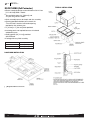
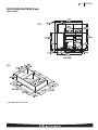
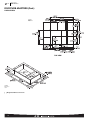
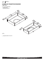
10. Roof Curbs (Vertical):
a. Formed galvanized steel with wood nailer strip and shall be capable of supporting entire unit weight.
b. Permits installation and securing of ductwork to curb prior to mounting unit on the curb.
11. Universal Gas Conversion Kit:
a. Package shall contain all the necessary hardware and instructions to convert a standard natural gas unit to operate from
2000-7000 ft (610 to 2134m) elevation with natural gas or from 0-7000 ft (90-2134m) elevation with liquefied propane.
12. Return Air Enthalpy Sensor:
a. The return air enthalpy sensor shall be used in conjunction with an outdoor air enthalpy sensor to provide differential
enthalpy control.
13. Indoor Air Quality (CO2) Sensor:
a. Shall be able to provide demand ventilation indoor air quality (IAQ) control.
b. The IAQ sensor shall be available in duct mount, wall mount, or wall mount with LED display. The set point shall have
adjustment capability.
14. Smoke detectors:
a. Shall be a Four-Wire Controller and Detector.
b. Shall be environmental compensated with differential sensing for reliable, stable, and drift-free sensitivity.
c. Shall use magnet-activated test/reset sensor switches.
d. Shall have tool-less connection terminal access.
e. Shall have a recessed momentary switch for testing and resetting the detector.
f. Controller shall include:
i. One set of normally open alarm initiation contacts for connection to an initiating device circuit on a fire alarm control
panel
ii. Two Form-C auxiliary alarm relays for interface with rooftop unit or other equipment
iii. One Form-C supervision (trouble) relay to control the operation of the Trouble LED on a remote test/reset station
iv. Capable of direct connection to two individual detector modules.
v. Can be wired to up to 14 other duct smoke detectors for multiple fan shutdown applications.
15. Barometric relief
a. Shall include damper, seals, hard-ware, and hoods to relieve excess building pressure.
b. Damper shall gravity-close upon shutdown.
26 29 23.12 Adjustable Frequency Drive
1. Unit shall be supplied with an electronic variable frequency drive for the supply air fan.
2. Drive shall be factory installed in an enclosed cabinet.
3. Drive shall meet UL Standard 95-5V.
4. The completed unit assembly shall be UL listed.
5. Drives are to be accessible through a tooled access hinged door assembly.
6. The unit manufacturer shall install all power and control wiring.
7. The supply air fan drive output shall be controlled by the factory installed main unit control system and drive status and
operating speed shall be monitored and displayed at the main unit control panel.
8. Drive shall be programmed and factory run tested in the unit.
67