1
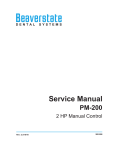
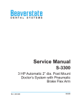
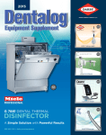
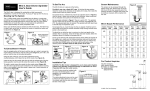
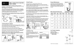
Beaverstate
DENTAL
SYSTEMS
Service Manual
C-3201
Asepsis Design Cuspidor, Vacuum
Accessory Group and Water QD.
(used with 144-057 side box only)
Rev: 2 2/18/10
900-074
C-3201
Installation
1. Place the shipping carton in the desired location. Remove the cuspidor from the
shipping carton.
2. Run umbilical through cuspidor hole in top of side box. Place cuspidor drain shaft
into hole.
3. Place the bowl, cup filler and bowl rinse spouts in their appropriate locations.
4. Connect the supply and vacuum tubings and gravity drain to the appropriate
connections.
5. Connect the low voltage wiring for the vacuum switch to the electrical source.
Final
Adjustments
Test the bowl rinse.
Test the cup filler.
Check for proper drain.
Test HVE and Saliva Ejector valve for proper function.
Adjust bowl rinse timer, if desired.
800.237.2303 ◆ 503.538.8756 ◆ 503.538.2845 Fax ◆ www.beaverstatedental.com
1
C-3201
Operation 1.
The cup filler is activated by pushing the cup filler button. The cycle stops automatically.
2. The timed bowl rinse is activated by pushing the rinse button. The timing for the rinse cycle may be adjusted with the flow control valve located under the cuspidor housing. To adjust the rinse cycle:
a. Turn adjustment knob counter-clockwise to decrease the rinse cycle time.
b. Turn adjustment knob clockwise to increase the rinse cycle time.
NOTE
The bowl rinse timer is set at the factory for 15 seconds.
This adjustment is very sensitive, only 1/8 of a turn will
increase or decrease the time significantly.
3. Flip the electric switch to activate the vacuum for the HVE and Saliva Ejector valve.
Cup Filler
Cup Filler
Push Button
Bowl Rinse
Push Button
Bowl Rinse
Timed Bowl Rinse
Adjustment Valve
under cover
Electric Vacuum Switch
located on side box
1/4" Female water QD
located on side box
Controls for Cuspidors
2
800.237.2303 ◆ 503.538.8756 ◆ 503.538.2845 Fax ◆ www.beaverstatedental.com
Autoclavable HVE & S/E Valves
Maintenance
Autoclavable vacuum valves may be autoclaved by steam autoclave or chemical vapor. Due
to the tight clearances and hardness of the anodized surfaces, the valve spool can become
jammed or seized in the valve if it is sterilized while contaminated with debris.
Valves can be quickly disassembled for cleaning.
1. Pry one side of the lever and flip it off of the valve. For saliva ejector valves, remove the
tip also.
2. Push out the valve spool and clean all the disassembled parts in an ultrasonic cleaner
daily. Rinse thoroughly before putting into autoclave.
3. Lubricate the O-Rings on the spool with a silicone based lubricant before reassembly.
ITEM
1
2
3
4
5
6
7
PART DESCRIPTION
PART NUMBER
Tip.........................................................112-174
Body.....................................................112-276
Spool................................................... 112-278
O-Ring #10........................................ 017-110
O-Ring, #12...................................... 017-012
Swivel................................................. 112-177
Lever.................................................... 112-181
QTY
1
1
1
2
1
1
1
autoclavable s/e lever valve
112-280
ITEM
1
2
3
4
5
6
PART DESCRIPTION
PART NUMBER
O-Ring, #13........................................017-113
Body.....................................................112-266
Spool....................................................112-268
O-Ring #13.........................................017-113
Swivel...................................................112-170
Lever.....................................................112-169
QTY
3
1
1
1
1
1
autoclavable standard hve valve
112-262
800.237.2303 ◆ 503.538.8756 ◆ 503.538.2845 Fax ◆ www.beaverstatedental.com
3
ITEM PART DESCRIPTION
PART NUMBER
1 Cup Fill Spout........................................ 132-068
2 Body, Cuspidor Spouts, Nickel......... 132-065
3 Plastic Elbow, 1/8"................................ 022-038
4 Water Valve, Push Button................. 132-018
5 Bowl Rinse Spout................................. 132-067
6 Air Valve, Push Button.........................132-020
7 Screw, 6-32 x 5/8"................................. 001-159
8 Flat Washer 5/8” x 1”............................ 003-001
9 Hex Nut, 5/8"-24................................... 002-518
10 Air Reservoir.......................................... 132-044
QTY
1
2
2
1
1
1
4
2
2
1
PART NUMBER
ITEM PART DESCRIPTION
11 Signal Valve. ........................................... 132-035
12 Cup Holder Drain Barb....................... 132-047
13 Screw, 10-32 x 1/4" .............................. 001-087
14 Plug, .652-1/2"....................................... 010-046
15 Bleed Valve. ............................................ 132-122
16 Drain Shaft. ............................................ 132-103
17 Bushing ................................................... 013-017
18 Universal Handpiece Holder. ........... 141-023
19 Vacuum Handpiece Holder. ............. 141-037
20 Drain Assembly.................................... 132-041
asepsis cuspidor
C-3201
QTY
1
1
4
1
1
1
1
1
1
1
ITEM
21
22
23
24
25
26
27
PART NUMBER QTY
PART DESCRIPTION
Holder Bar............................................... 132-111 1
Cuspidor Frame.................................... 132-102 1
Screw, 10-32 x 3/4" .............................. 001-034 4
Cover. ....................................................... 132-101 1
O-Ring, Ceramic Bowl......................... 017-150 2
Bowl, Ceramic........................................ 132-110 2
Strainer. ................................................... 132-008 1
4
PART NUMBER QTY ITEM PART DESCRIPTION
PART NUMBER QTY
ITEM PART DESCRIPTION
PART NUMBER QTY ITEM PART DESCRIPTION
9 Hinge ....................................................... 107-083 2
1 Adapter, Pelton Crane........................146-208 2
17 On/Off Electric Toggle Valve. ...016-020 1
10 Door, Side Box....................................... 144-062 1
2 40” Side Box Post ................................146-204 1
18 Plug, .1/2”........................................ 010-013 3
11 Cuspidor.................................................. C-3201 1
3 Riser Post.................................................144-064 1
19 1/4” Panel Mount QD. .................024-003 1
12 Nyliner Bushing.................................... 013-014 1
4 Bottle System (Optional)...................144-054 1
20 Needle Flow Valve .......................121-000 1
13 Vacuum Cannister................................ 131-021 1
5 Screw, 10-32 x 1/2“..............................001-057 2
21 Plug, 3/4”. .........................................010-005 1
14 Screw, 6-32 x 3/8”................................. 001-041 2
6 Aluminum Block ..................................144-063 1
22 Power Cord, 6’. ...............................016-035 1
15 CV Cannister Mounting Bracket. .... 131-038 1
7 Hex Nut 6-32, 1/4”................................002-026 8
16 Screw, 8-32 x 1/4”................................. 001-003 2
8 Lock Washer #6.....................................003-012 8
5
asepsis cuspidor used with 144-057 SIDE BOX
C-3201
Quick-disconnect Syringe Tip Assembly 113-230
1.
Remove the existing hex nut. A hex nut wrench has been
provided.
2.
Remove the syringe tip adapter using the hex wrench.
3.
Insert the new syringe tip adapter into the syringe head and
tighten using the hex wrench.
4.
Place the two (2) O-Rings into the syringe tip nut.
5.
Screw the syringe tip nut onto the syringe tip adapter and
tighten using the hex wrench.
6.
Push the syringe tip into the syringe tip nut until it snaps into
place.
Replace Syringe Tip
1.
ITEM
1
2
3
4
5
6
7
8
9
10
11
12
Pull the dirty syringe tip out and insert a clean syringe tip into
the syringe tip nut until it snaps into place.
PART DESCRIPTION PART NUMBER QTY
Syringe Tip ..................................113-030 1
Syringe Tip Nut ............................113-402 1
O-Ring, 006 .................................017-006 2
O-Ring, 228-040 ..........................017-023 1
Syringe Tip Adapter ..................... 113-227 1
O-Ring, 003 .................................017-003 1
Syringe Head...............................113-405 1
Syringe Button Repair Kit ............113-403 2
Pin, Syringe Cartridge .................113-008 1
Plastic Washer, 8-32....................003-030 2
Barb, 8-32 x 1/16’’ .......................022-040 2
Syringe Handle...........................113-236 1
3-way ic syringe
113-400
6
ITEM PART DESCRIPTION
PART NUMBER
1 Stem ................................................................... 132-124
2 O-Ring, 003....................................................... 017-003
3 Body................................................................... 132-123
4 Set Screw, 4-40 x 1/8" ................................... 005-030
5 Plastic Waher, 1/4" ......................................... 003-001
6 Barb,m 10-32 x 1/16".................................... 022-009
7 Plastic Elbow, 10-32 x 1/16" ....................... 022-039
7
QTY
1
1
1
1
1
1
1
bleed valve (cuspidor)
132-122
ITEM PART DESCRIPTION
PART NUMBER
1 Syringe Button......................................113-401
2 O-Ring, 007............................................. 017-007
3 Dress Nut ................................................ 002-517
4 Body..........................................................132-028
5 Plastic Washer, 1/4"..............................003-001
6 Barb, 10-32 x 1/8"................................. 022-010
7 O-Ring, 001............................................. 017-501
8 Stem ......................................................... 132-021
9 O-Ring, 002............................................. 017-502
10 Spring ...................................................... 008-023
11 Plug .......................................................... 020-026
push button valve, water (cuspidor)
132-018
ITEM PA
1 Sy
2 O
3 D
4 A
5 Se
6 V
7 O
8 St
9 O
10 Sp
11 P
12 B
QTY
1
1
1
1
2
2
2
1
1
1
1
8
push button valve, air (cuspidor)
132-020
ITEM PART DESCRIPTION
PART NUMBER
1 Hex Barb, 10-32 x 1/16" ............................... 022-009
2 Plastic Washer, 1/4" ....................................... 003-001
3 Valve, Air Pilot ................................................. 014-002
4 Cup Seal ............................................................ 017-203
5 Piston, Air Pilot................................................ 014-008
6 Stem, 2-Way Toggle Valve........................... 120-013
7 Spring, Toggle Valve...................................... 008-002
8 Body, Toggle Valve......................................... 120-010
9 Hex Barb, 10-32 x 1/8".................................. 022-010
9
QTY
1
3
1
1
1
1
1
1
2
signal valve
132-035
10
Master Valve (may require inserting an
additional barb).
1/4" Blue - Connect each to 1/4" barb on Water
ribbed.
1/8" Clear - Tee into Foot Control tubing,
Circled letters indicate connection at Junction Box
Junction Box
Air Reservoir
132-044
Cup Fill Drain
Vacuum Cannister
131-030
Relay Valve
132-035
Asepsis Cuspidor
C-3201
Cuspidor Bowl
S/E Valve
112-280
5/8" Sterling
1/2" Sterling
BEAVERSTATE DENTAL, INC.
115 S. ELLIOTT RD.
NEWBERG, OR 97132 USA
800-237-2303 503-538-8756
503-538-2845 FAX
Revision Date: 6/20/07
HVE Valve
112-262
3/8" Sterling
1/4" Blue
1/8" Clear
1/4” Water QD
016-020
Electric Switch
016-020
Bowl Rinse Spout
132-062
Air Valve,
Push Button
132-020
Water Valve,
Push Button
132-018
Cup Fill Spout
132-062
Bleed Valve
132-122
Tee