1
Sept. 23, 1958
F. ADAM
2,853,291
JAIL. LOCKING DEVICES AND THE LIKE v
Filed Dec. 14, 1955
5 Sheets-Sheet 1
Sept. 23, 1958
F. ADAM
'
2,853,291
JAIL LOCKING DEVICES AND THE LIKE
Filed Dec . 14, 1955
5 Sheets-Sheet 2
11.
I
1
53
6'
47..
m/l
-
1/14
5o
\
I
' I O Q '
v".
9 am.
..
lnvenfoé':‘
-i-_oige A am,
hm
Sept. 23, 1958
F, ADAM
v2,853,291
JAIL LOCKING DEVICES AND THE LIKE
Filed Dec. 14, 1955
5 Sheets-Sheet 3
Sept. 23, 1958
F. ADAM JAIL LOCKING DEVICES AND THE LIKE
Filed Dec. 14, 1955
2,853,291
5 Sheets-Sheet 4
‘R
Q
Q
Fig.
9.
I
Sept. 23, 1958
F, ADAM
2,853,291
JAIL LOCKING DEVICES AND THE LIKE
Filed Dec. 14, 1955
5 Sheets-Sheet 5
ESL
United States atent 'O ‘ice
1
_,
2,353,291
Patented \Sept. ‘23, 1958
2
as an arm or a leg, between the advancing door edge
and the abutment or pilaster at the'door closed position,
an amount of compressive force‘will be exerted against
such obstacle or such human body-as willrbe required to
“stall” the motor under the current supply conditions
2,853,291
JAIL‘ LOCKING DEVICES AND THE LIKE
then obtaining. Such compressive force will ‘generally
Folger Adam, Joliet, ‘ Ill.
be severe so that serious ‘bodilyrinjury .to-the individual
might be produced; ‘and additionally, thestalling of-the
motor with full voltage being applied thereto would
10 probably result in serious damage'or burning out of the
Application :December‘1'4, 1955, Serial No. 553,081
5 Claims. '(Cl. 268-53)
'
motor, even in cases where such protective elements as
fuses might be provided‘for protection against such an
emergency. It is also to be noted, that’once a compres
sive force had been developediagainst suchobject, ‘the
' This inventiontrelates to improvements in jail lock 15 discontinuance of current supply to the motor would
ing devices, and the like. The improvements herein dis
not serve to release continuance of such. compressive
closed have to do primarily with electrically controlled and
force, since such release would require backing up the
operated jail lock and door moving installations. More
motor through the gear reducer-train which is generally
tparticularly,Tsaidimprovements concern such installations
irreversible, that-is, cannot bedriventhrough-force ap
in which there are provided motor drives for ‘the indi 20 plied to its driven end.
vidual doors, be they cell doors, or other jail and/or
The foregoing objections to such arrangements as are
prison doors, each such door being provided with its in
disclosed in that earlier applicatio-nyare supplemented by
dividual electric motor for door drive in either direc
the following further feature:
tion as required; together with operating and controlling
In such installations aspare (provided with individual
connections between each such motor and its {associated 25 driving motors it is customarypandagenerally necessary,
door. The .present improvements have to do with said
to provide “limit switches” radjacenttorthe door ‘closed
operating and controlling connections, and include ,cer
and door openlimited positions. .Theseswitches are, so
tain safety features to protect both the installation and
constituted and sorelated .to.the door structure‘or-ele
individuals or objects which may be trapped between the
ments carried thereby: that whenthe doorreachesits .in
closing door and the abutment ‘at .the door closed posi
tended limit of movement the corresponding.limitrswitch
tion, so't‘hat damage willnot be done tosuch object or
compressive force due to the continuedv drive of thedoor’s
compresive force'due to‘the continued drive of thedoor’s
is operated,Y-thus cutting o?'vcurrentfrom‘ the motor (and
from theclutch, which-clutch is .then. movejdjto its dis
connected position by such spring). ‘But such limit
motor.
switch will not thus functionruntil the-doorreaches its
intended limited. movementposition. Therefore, in ,case
This application discloses said features particularly as
embodied in thatform of door controlling and operating
mechanism .disclosed in my co-pending application for
Letters 'Patent of the United States, Serial No. 386,231,
of t presence of an obstruction orhuman bodybetween
the door edge. and the abutment .or. pilaster atthe door
closedposition,~ so that. complete door closing movement
could not be effected, it is seen that the doorclosed limit
switch‘would not function, and current would vnot be
cut o? from the motor and clutch. .Thus, .the provision
of such limit switch at the door closed position would
notserve as a protection against the continuance of cur
rent delivery to the motor, nor. against continuance of
the clutch engagement.
It is also to be noted that even when-current supply
to the clutch is discontinued simultaneously with vdis
continuance of current supply tothe motor, the disen
?led by .me October 15, 1953, but I wish to make it
clear thatthe-present improvements are not to be under
stood as limited to thatearlier type of construction, ex
cept as I‘may limit myself to the same in ‘the, claims
to follow.
In order-‘to better understand thepresent features of
inventioniandtheir relation to other elements of the in
stallation, the following statement is in order:
'
‘In that earlier application I ‘have provided -for each
door a drive motor individual thereto, and'located sub
stantially at thelocation of its door. This motor 'drives
The electric circuits are ‘so ‘constituted
gagement of the driven and driving elements of, the clutch
does not necessarily occur immediately, nor until torque
which has been developed between these elements has
been released. This is especially true inthe‘ case of tooth
type clutches in which one of the elements ,is movable
that the clutch, which is normally’ disengaged, is driving
axially towards and from the other‘element duringtthe
a sprocket or other driving element for a tension :mem
'ber,\through a suitable gear speed reducer'(if needed),
and through 'aclutch"element, generally of electrically
operated ‘type.
lyt engaged when and during the time that current is sup
clutching. and declutching operations. _Accordingly, ex
plied to the motor, so that during such motor current
perience ‘has shown that frequently, when jsuch tooth
supplying operation the clutch is also engaged to effect
type clutches are used in such installations as the present,
drive to the door operating mechanism. In that earlier
namely operating and controlling cell or other prison
application'such clutch comprises that type in which the
door movements, the discontinuance of current delivery
driving and- driven clutch elements are provided with co 60 to both the motor and the clutch_ will not result inde
operating clutch teeth which are normally disengaged
clutching, so that manual movement of the door back
from each other under urge of a spring so that under
wardly cannot be produced to release the trappedobject
these conditions the doormay be moved back and‘forth
readily under manual force -for ‘door opening and/or
speed reducer.
closing, and without need of simultaneously driving the
motor through said gear speed reducer. In that earlier
application such clutch is of such design that drive be
or human body, due to the irreversibility [of the gear
65
The present disclosures include‘ provision of a type ‘of
clutch in such installations, which clutchis ofv such de
sign and operation that all of the foregoing objections
tween the motor and the door operating mechanism, or
to’ previously used and included forms of, clutch‘are‘over
such driving connection, will occur at all times during
come and greatly improved operations are produced.
which the clutch’ is electrically energized to bring its ‘driv 70 The clutches herein disclosed for such installationsand
ing and driven elements into co-ordination. Thus, in
purposes and operations are'of va type which may be
case of presence of an ‘obstacle ‘or a human body,‘such ' ‘designated as a frictional ‘and magnetic‘face ‘engaging
2,853,291
3
type. These clutches are provided with two co-operating
elements, one the driving element, and the other the
driven element. One of these constitutes the ?eld ele
ment and the other constitutes the armature element.
Provision is made for energizing the ?eld element to
produce the needed magnetic flux which acts through a
magnetic circuit including both the ?eld element and
the armature element, drawing them together under force
4
operating movements may be effected manually without
need of driving the motor or the gear speed reducer
(when one is used). In the present embodiment the
clutch when clutched drives a shaft which in turn is
operatively connected to the proper controlling and
operating elements. Accordingly, by manually rotating
this shaft in either direction when the current is off,
either by failure of supply or by opening of the switch,
such manual rotation of this shaft produces the desired
which is substantially proportional to the square of the
?eld strength, and thus producing a frictional engagement 10 operations. Such shaft extends normal to the face of the
protective cover which encloses the clutch and various
between the two elements with corresponding driving
other elements. I have therefore provided an opening in
effect between them. The clutch construction is such
such cover in alignment with such shaft so that, when
that when such ?eld is discontinued by cessation of cur
manual operation is to be produced, a suitable hand
rent ?ow the gripping effect is terminated, with corre
grip'element may be set onto the end of the shaft
sponding declutching result. Normally the armature is
exposed through such opening, such hand grip element
slightly separated from the ?eld element so that actual
being outside of the enclosure, and then the rotation in
contact does not exist; but such separation is so small
proper direction 'may be conveniently produced. I have
that only a slight axial movement is required to produce
also provided a movable cover plate adjacent to the
engagement for drive. Such axial movement occurs im
inside face of the enclosure at the location of such open
mediately that current flow through the ?eld coil is
ing, which cover plate may be shifted between a normally
produced, so that almost instantaneous engagement of
closed position in which the opening is closed against
the clutch takes place when the motor and clutch are
insertion of the hand grip element or any other tool,
electri?ed. Likewise, when current is cut o?r from said
and an open position in which such opening is uncovered.
motor and said clutch the clutching engagement ceases
I have also provided a key locking device for effecting
at once, and there is no tendency for the clutch elements
shift of such cover plate between its two positions, so
to “hang on” as is a serious detriment to use of the
that the opening can be uncovered only by .use of a
tooth type clutches in such installations. This combina
tion of parts or elements constitutes an important part
proper key.
Other objects and uses of the ‘invention will appear
of my present invention.
I have hereinafter illustrated and shall describe one 30 from a detailed description of the same, which consists in
the features of construction and combinations of parts
embodiment of such a clutch in the present combination,
hereinafter described and claimed.
as illustrative of my present invention, and as consti
In the drawings:
tuting a good operating combination of the elements; but
in so doing I wish it understood that I do not thereby
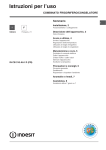
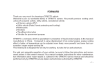
Figure 1 shows a front face view of the upper, door
intend to limit myself to this particular embodiment of
closed portion of a door operating unit, including the
clutch element which embodies the features herein de
such a clutch, except as I may do so in the claims to
scribed; and this ?gure also shows the limit switch for
follow.
It is to be noted that when using the type of clutch
the door closed position;
Figure 2 shows a cross-section taken substantially on
herein disclosed for the present combination, the holding
power of the two clutching elements is substantially pro
the line 2—2 of Figure 1, looking in the direction of
portional to the square of the exciting current, assuming
the arrows; and this ?gure shows a longitudinal or side
that the magnetic elements of the clutch including its
elevation of the clutch and adjacent parts;
iron are being operated at a saturation below the “knee”
Figure 3 shows a longitudinal section through the
of the magnetization curve. Accordingly, one feature of
clutch and adjacent parts illustrated in Figure 2, and is
the present invention includes the provision of means i also a section taken substantially on the lines 3—-3 of
to adjust the magnitude of this exciting current so that
Figures 1, 4, 5, 6, 7 and 8, looking in the directions of
the holding power developed by the clutch will always be
the arrows;
su?icient to ensure dependable operation under normal
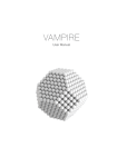
Figure 4 shows a front elevation, on reduced scale as
door closing operations, and to the complete door closed
compared to previous ?gures, showing the left-hand por
position, with‘ corresponding reversal of the limit switch 50 tion (door closed portion) of a cell door and the left
at the door closed position, but with assurance that
excessive clutch holding power will not be developed.
Thereby the bene?ts of both primary operating condi
tions will be satis?ed. Sometimes the door closed limit
switch may be functioned by the movement of the
locking element to its door locked position, a condition
which occurs after the door has actually reached its fully
closed position. Accordingly, I have herein disclosed
one arrangement in which such limit switch is caused to
function when such locking element has actually moved 60
hand abutment or pilaster structure, with a portion of the
structure cut away to reduce the height of the ?gure;
and in this ?gure the cell door is in closed position
against the pilaster, and the limit switch has functioned
to cut off current to the motor and clutch;
Figure 5 shows a cross-section through the clutch ele
ment, substantially on the line 5-—-5 of Figure 3, looking
in the direction of the arrows; and this ?gure shows the
exciting ?eld producing element;
Figure 6 shows a cross-section through the clutch ele
ment, substantially on the line 6--6 of Figure 3, look
tion of all movements needed to produce door closed
ing in the direction of the arrows; and this ?gure shows
and locked condition prior to cutting off the motor and
the engaging and friction producing face of the ?eld ele
clutch current. Speci?cally, the presently illustrated
ment of the clutch, which ?eld element is drivingly con
embodiment is one in which the door locking is effected
nected to the shaft;
by down movement of a vertically movable locking bar;
Figure 7 shows a cross-section through the clutch ele
and the door closed and locked limit switch is caused to
ment,
substantially on the line 7-—7 of Figure 3, look
function by the vertical movement of this bar to its door
ing in the direction of the arrows; and this ?gure shows
closed locked position.
A further feature and object of the invention relates 70 the smooth armature face which is drawn into engage
ment with the excited ?eld element;
to the provision of means to enable convenient manual
Figure 8 shows a cross-section through the clutch ele
operation of the door controlling and operating elements
ment, substantially on the line 8-8 of Figure 8, look
when desired or required, as when the current supply
fails. Under such conditions the clutch is de-energized
ing in the direction of the arrows;
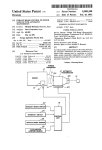
Figure 9 shows more or less schematically, a typical
and de-clutched, so that the necessary controlling and
to its door locked closed position, thus ensuring comple
5
,
twiri'ngfdia‘g'ram for a single cell installation
embodying
‘which ‘it is" attached so that when‘suchshin in'either "direc
“ the’ features of the. presentinvention;
" tion' has ‘been ‘ful?lled’ further'driven "movement 'of ' such
'Figure 10 shows-.a‘fragmentary‘face view of vthe upper
‘left-hand portion of the Structure shown invFigures 1
and 4, but with the protective cover in place; and this
‘bar in ‘such direction'iwilLse’rve’to? move'the "door with
‘the angle bar.
‘
The details‘of this lost-motion connection
inserted when such ‘opening is uncovered by use of a
need not be illustrated‘here. Each ‘end of such angle
bar‘ has connected to its lower ?ange face a downwardly
extending blockl'23 (only'the left one of which is illus
trated in Figure 4), an'da tension rod -.24 is extended
special key,.thus making-it possible to manually operate
through such block. The ‘outer projecting end of each
?gure shows the opening in such cover plate through
which a manually operated handjgrip element may be
10 such tension'rod is connected to the, proximate‘end of
‘the shaft and connected parts;
the chain ortension element ‘20. The inner end of each
Figure 11 shows a plan view corresponding to Figure
such tension ro'd carries a nut"25- which isia‘djustable along
10; and
such rod; and a compression spring'26 isi-locate'd on the
Figure 12 ‘shows aifragmentary vertical view of the
rod between the corresponding nut and the inner face
upper portion of the right-hand upperportion of ‘the
structure, showing the upper portion of the vertically mov 15 of the corresponding block, so that by adjustment of such
able locking bar, "and also showing‘ the limitswitch in
position for operation by the vertical movements of
nut the compression of “the spring may be adjusted. In
other words, the pre-loading of such-spring may'be ad
justed thereby. "Thus it will be seen that a closed loop
‘
is provided-including the upper run of the chain, the chain
Referringi?rst to Figuresland 4, I have therein shown _
the features of m'ypresent invention as applied to a typical 20 runs .over'the twoend sprockets, the'short chain runs
between the sprockets and the proximate tension rods,
installation of aicell door. 'To this'en'dlI have shown
and the upper portion oft-the door itself. “It will also
the left-hand or door closed end of a sliding door 10 the
be seen that when pull is vexerted'on the chain in either
same being carried by rollers 11 .(only one of which is
su'ch‘locking bar.
shown) which are journalled to the upper portion of
the door, and ride along-a trackway 12 carried by the
lower and horizontal ?ange 13 of an angle section'14.
The lowerledge portion of ‘this door is guided by suit
direction by drive of the sprocket 18 some movement
of the sproeketand chain may occur without and prior
to corresponding door movement, such independent chain
~movementbeinglpermittedby compression of the spring
26 at thelocation or end at whichl'force'is being applied
to the door; and such movements of compression of spring
30 at such drive end being accompanied bycorresponding ex
tion of elements.
pansion of the spring at the» other end of-the door. YThus
"The door locking elements are partly Yshownherein,
such . chain movement independently of the door is
as they constitute'noportion of the present invention.
produced while at the same time permitting the chain to
It may be stated, howeveijthat in’the type of structure
belkept taut and in good running condition over the two
to which my present improvements are generally applied
such locking arrangements include a ‘vertically movable 35 sprockets. vlit is noted thatsuch movement of the chain
produces its door 'drive through the instrumentality of
‘locking bar, carried by-‘the permanent structure, and nor
the slidebar 21, only to the permitted limit of such slide
v‘mally occupying a lowered position in which the. ‘sliding
bar movement, after whichdoor movement is produced;
door is lockable in either its closed or its openp'osition.
andsuch slide bar movement is also used to effect verti
This locking bar generally occupies a location close to
an abutment or pilaster passing which the door moves 40 cal movement upwardly of the locking bar forsdoor un
during opening and closing movements. Such pilaster - locking. All of the ‘foregoing structural features are
fully disclosed in my aforesaid co-pending application
and vertically movable locking bar are not shownin
Serial No. 386,23 1 and various of said features are claimed
Figures 1 and 4 as they would occupy a position to the
able structural elementsnot herein ‘shown as they con
stitute no portion of thepresent' invention and combina
right of elements shown in said ?gures. During closing
' in that application.
movement the door’s left-hand edge comes to or close 45
Adjacent to the limit of movement of the door in each
direction there is supported a limit switch by the struc—
ture. Only the left-hand or door closed limit switch is
Pshown in'Figures 1 and 4, there designated as 27; but
a right-hand or door opened limit switch 23 is also shown
in vFigure 9. ‘This one is located at position to function
properly when the do0r:is fully opened. Each such limit
to the vertical abutment or pilaster 15 (see Figure 4)
at which position the door is normallylocked closed.
In Figure 4 I have also shown a’?ange or bar '16
carried by the lower edge of the door and which is
provided with a notch 17 in its lower edge. A suitable
latch engages with thisnotch when the door is in its
fully opened position to'retain the door in such open
switch conveniently comprisesra form of microswitch hav
position. This latch is connected to and moved by the
ing
and the
a plate
light 31
spring
is hingedat'32
leaf element in29position
carryingsoa that
rollerwhen
vertical movements of the vertically movable locking bar
to produce the desired locking of the lower edge of 55 such plate is raised it engages the roller and thus forces
up the light spring leaf against its bias, thus also depress
the door at the extremes of door movement.
ing the microswitch button and reversing such switch leaf
The opening and closing movements of the door are
contactfor the desired function. The end of the slide
directly produced in the following manner:
bar ‘21 which approaches each limit switch is provided
A sprocket wheel 18 is mounted on a shaft 19 located
somewhat to the left of the leftward extreme of door 60 with a slanting or cam shaped plate 33 whose cam sur
face 34 isadapvted‘to engage a stud projecting towards
movement. This shaft is suitably journalled as will be
presently described. A companion sprocket wheel (or
idler) is journalled to the structure at a location some
what rightwardly of the fully opened door right-hand
edge,v such sprocket not being herein shown in order
to shorten the'?gures. A chain or other tension element
2% passes over both of the sprockets and has its ends driv
ingly connected to the upper left-hand and right-hand
corners of the door through suitable instrumentalities
which need not be illustrated or described herein. How
ever, these include a slide-bar lost-motion element which
includes the bar 21, conveniently in the form of an angle
bar having its lower flange 22 projecting towards the ob
‘server in Figure l. T his angle bar is capable of‘ a limited
. amount of horizontal shift with ‘respect to ‘the door' to
the observer in Figuresd and 4, such stud being desig
nated 35 and carried by the plate >731. ‘Any other suit
able means 'may be provided for reversing the limit
switches at the intended limits of door movement. These
features are also disclosed in my aforesaid co-pending
application, Serial No. 386,231.
.The motor drive for the sprocket wheel 13 is best
shown in Figure 1. The motor 36 is carried by a bracket
37 supported by'the structure. This motor drives the
gear speed reducer 38 through the shaft coupling 39.‘
The driven shaft 40 of the'gear speedv reducer'carries a
sprocket wheel or pulley 41. ‘The'shaft 19 which carries
the sprocket‘wheel 18 also‘ carries the sprocket or pulley
wheel’42 which is'driventby ‘the gear~reducerwheel ‘41
"
2,853,291
PI
1
~ 8
through the use of the chain or belt 43.
Generally the
gear speed reducer is of the worm and worm gear type
and irreversible, so that drive backwardly from the shaft
41 to the shaft of the coupling 39 cannot be effected; but
even if such gear reducer were not of irreversible quality
such backward drive would entail drive of the motor’s
armature, with corresponding substantial load of drive
blocks. Also, since no actual metal to metal engage
ment occurs between the ?anges 59 and 60 and the sur
face of the armature element 53 there is produced no
magnetic “lock” such as would tend to retain the driving
engagement between the parts after magnetization had
ceased by termination of the electro-magnetic energiza
tion to be described presently.
Thus, as soon as de
imposed on the sprocket or wheel 18 when such drive
magnetization occurs the armature element will be freed
might come from an attempt to move the door manually.
of drive to the element 55, which is the effect desired.
I have interposed a clutch element of special character 10
The magnetization of the ?eld element 55 is produced
istics between the sprocket wheel or pulley
and the
by induction as follows:
sprocket wheel or pulley 42 from which the drive of
A coil unit 6111 is freely mounted on the sleeve 56
the chain 20 is derived, so that normally the sprocket 18
of the ?eld element so that rotation of the ?eld element
and chain 20 are disconnected from the sprocket 42 and
may occur without corresponding rotation of the coil
motor drive, but so that when the motor is energized for 15 unit 61a. Preferably a bushing 62a is set between said
drive in either direction such clutch element is also ener
elements as shown in Figure 3, or an anti-friction bear
gized to effect drive from the sprocket wheel or pulley
ing such as a ball or roller bearing may be used at this
42 to the sprocket wheel 18 and the chain 20. Such
location. This element 61a includes a deep annular
clutch arrangements are as follows:
~
recess 63 into which is set a coil 64 having its axis parallel
Referring especially to Figures 2, 3, 4, 5, 6, 7 and 8, 20 to the shaft axis, so that magnetization ?ows through the
the shaft 1? is freely journalled in the bracket arms 44
central portion of the coil element in axial direction.
and 45 which depend from the plate 46 secured to the
The left face of this element 61a is provided with a
bottom of the bracket arm 47 of the angle plate 48. This
deep but radially narrow recess 65 into which seats a
angle plate is in turn secured to the structural plate 49.
rightwardly extending narrow ?ange 66 of the element
The sprocket wheel 18 is secured to the shaft as shown 25 55, the parts being so proportioned that actual contact
in Figure 3. Conveniently such securing is produced by
between the elements 55 and 61a does not occur during
use of the ?anged block 50 keyed to the shaft 19 by the
drive running. The element 61a is also provided with
key 51. The ring sprocket element 52 is then set onto
a radially narrow ?ange 67 which overlies the outer
the shouldered portion of such block 50 and secured in
periphery of the element 55 with slight clearance between
place by the screws as indicated. Thus the shaft 19
the parts. A thin ring 68 may be set between the inner
and sprocket wheel element 18 are locked together and
?ange of the element 61a and the proximate right-hand
rotate or stand idle as a unit.
surface of the element 55 to prevent the elements 61a
A similar structure is shown in connection with the
and 55 from being drawn into direct metal to metal
sprocket wheel 42. In this case, however, the ?anged
engagement under magnetic attraction when the coil 64
block 53 which carries the sprocket wheel ring is mounted 35 is energized.
for free rotation on the shaft, a bearing element 54 being
The energization of the coil 64 will serve to mag
located between such ?anged block and the shaft. Such
bearing element is indicated as a bushing, but evidently
any suitable type of antifriction bearing might be used,
such as a ball or roller bearing.
Accordingly the drive
from the sprocket wheel 42 to the shaft 19 is dependent
on producing drive from the element 53 which carries the
sprocket, to the shaft 19.
The element 53 may be considered as the armature of
netize the element 55 by induction and without frictional
engagement between the parts. It will be seen that the
path of ?ux between the various elements will be as
follows: From the ?ange 67 (of the element 61a) to
and through the ?ange 60 of the element 55 to the face
of the armature element 53. By providing the overlap
between the ?ange 67 of the element 61a and the outer
surface of the element 55 there is induced a direct ?ow
The right-hand face of the ele 45 of ?ux to the ?ange 60, and thence to the face of the
ment 53, especially the ?anged portion thereof, is smooth,
armature element by a short path. If desired the ?ange
and comprises material of good magnetic permeability
portion of the element 55 may be formed by non-magnetic
a magnetic clutch unit.
such as iron or one of the soft magnetic alloys.
This
element 53 is capable of slight shift rightwardly on the
material between the ?anges 59 and 60, such ?anges,
. however, being of magnetic material, so that any mag
shaft (amounting to one or a few thousandths of an inch) 50 netic short-circuiting tendency between said ?anges 59 and
when clutching is to occur, and like leftward shift when
declutching is to occur. A ?eld element 55 of generally
?ange ‘form is secured to the shaft 19, being provided
with a rightwardly extending sleeve portion 56 directly
60 will be greatly reduced, and the ?ux strength de
livered to the face of the armature plate will be cor
respondingly increased. In this connection, too, the pro
vision of the rightwardly extending ?ange 66 of the ?eld
mounted on the shaft and keyed thereto by the key 57. 55 element reaching into the annular recess 65 of the coil
Accordingly rotation of such ?eld element must be ac
element, will tend to induce direct ?ow of ?ux in such
companied by shaft rotation in the same direction. This
manner as to strengthen the ?ux delivered through the
?eld element’s ?ange is provided with an encircling re
armature plate surface.
cess or groove 58 (see Figures 3 and 6) which faces the
The coil element remains stationary while rotation is
smooth face of the armature ?ange 53. This encircling
being produced of the elements 53 and 55, the magnetiza
or annular recess provides the inner and outer narrow
tion being produced inductively as stated before. Accord
?anges 59 and 60 which may be directly engaged by the
ingly, the two terminals of the coil 64 may be permanently
surface of the armature element when that element is
connected to the proper current supply circuits without
shifted slightly rightwardly under magnetic attraction.
Or, preferably, a number of friction blocks of segmental
form, 61, may be seated into the recess and secured in
place by rivets 62, such friction blocks being of slightly
greater depth than the ?anges 59 and 66 so that when
magnetic attraction between the ?anges and the arma
need of using slip-rings which would be seriously objec
tionable in such an installation as that for con?ning
persons convicted of felonies. I have shown the element
61a as provided with the radially extending ?ange ele
ment 69 through which is extended a pin 70 carried by
a bracket 71 secured to the underface of the element
ture surface (element 53) occurs thefriction material 70 46. Preferably the opening through which such pin
blocks will come into ?rm engagement with the arma
passes is slightly enlarged radially, as shown in Figures 5
ture surface before ‘engagement occurs between the
?anges 59 and 6t) and the armature. Accordingly, the
drive between the armature and ?eld elements will be
and 6 so that the element 61a is free to adjust and center
itself with respect to the element 55.
A ring element 72 is placed on and locked to the
produced frictionally through the medium of the friction 75 shaft 19 just to the right of the element 61a so that all
9363mm
'10
,provide’dlfonlgiving'to theattendant or .guar‘d a Signal
.of.the r clutch .elements areiretaine‘dfin proper relative
Ipo'sit-ions..on.ithe-shaft, such.ring .elementtrotating with
‘ when'the'doorfis actually closed and brought‘to its locked
the .shaft while‘, the :element. 6 lal is , stationary.
closed condition. Accordingly, when such signal fails‘to
Now‘it,is ‘noted that the magnetic ?ux.'d_cvelope'd'-by
respond after the usual lapse of time needed for door
closingithe attendant may come to such door, examine
inland if needed, ‘remove any obstacle which he P?n'ds
"in place to prevent the complete door closing movement.
~It>is founddhatclutches of the type herein illustrated
-. the ». coil 7 6-4 will .be . generally , proportionate to .the .cur
rent 'streng'thrthrough such coil, assuming that ‘the mag
Fnetization is occurring in :amount .below the knee .of
thesaturationacurve ofthe magnetic‘ path. [Since the
admirablyperform all *of the ‘required functlons,-and
iments'is proportional-tor.the..product of their-strengths, 10 comply with the conditions-explained ‘above. ‘This'is
tandvzsince 1 the x strengths-‘of “both elements of the ?eld. are
‘because, among other things, such clutches producefdrive
.magne?c I attraction- between the. ?eld .and armature rele
rthesame, littfollowstthat the attraction under the con
ditions existing in the clutch herein disclosed will :be
[generally proportional "to .the square ‘ of the supplied
“current. :I haveprovide'd meansvto adjust the value of
‘that =current ‘to i meet the :operating :conditions .of the
jpresent installation, as willgpresently, appear. The fol
lowing comments are ,pertinent . to .a determination of
what that currentfandtthe holdingtpower of .theaclutch
should- be:
‘It ris desired ‘that .the holding :power ‘of the clutch
shall‘ be "sufficient to ensure dependable operation ofthe
ffromithe .driving 'to the driven element through ‘facial
engagement of.>surfaces normal to the axis‘ of ‘shaft rota
tion, and because the driving .force which willlbe de
15 veloped depends .almost .directly on the facial .pressure
exerted between "suchsurfaces. It is further noted that
theprovision of thefriction-material inserts or blocks'f61
carried‘by the. field element v55-serve to, produce .a fric
tional contact ofisuch nature that (whenslip'is forced-t0
20 occur by exerting a. su'?icient'holding ‘force against the
drivenJelementsuchslip will'be a smooth .‘sliding action,
generally Tdevoid .of chatter,‘ jerks and other objectionable
ndoor forleontrolling sand operatingdevices, butxnot suf
1' irregularities of drive. "Furthermore, such inserts or blocks
i?eie‘nt to tcause ‘serious harm to<objects which maybe
are replaceable on occasion by:simple operations.
v,present ‘between : the .door I‘ edge \73 I and ' the abutment or 25
{commences _pull~is-.exerted:on the chain 20 ‘towards the
.As one exampleof sucha clutch as just ‘described,iand
which will respond totheconditions outlined hereinbe
Jfore,'I'refer to the clutches manufactured by the vWarner
iElectric'Brake .& Clutch Company, - of.’ Beloit, Wisconsin,
and shownin their “Service Manual" for electric sta—
rleft ' on .the ‘lower ,chain =run 'thus ; pulling on the rod . 24 30
tionary ‘?eld clutchcouplings, Models 160-250-4100,
ippilaster ‘15 (.Figure 4). , .Assuming that'the [door is in
fits-fully=openedsrand ‘locked open position the vertical
:locki‘ngibar leisllowered. As the door closing operation
and compressing the spring .25 to some extent. :This
v,pull will :urge -.the slide bari21—~22rleftwardlyrto "take
‘up the ‘lost -.motion ‘prior :to commencing leftward t. door .
aclosingrmovement. This-leftward-movement of theslide
ibar~lwilltcausetheicam edge=34 to'raise the ‘.loeking‘bar
‘,(said cam edge being then in its ‘rightward or --door
-ope11,;.position, not illustrated in Figures land 4). As
:soontasdheiloekingbanhas thus been raisedltorthe door
7
which manual carries EormiNo. WEB 6174. lI-Iowever,
.11 do notjintend tojlimit myself to these particularmanu
“facturesof'clutches, nor -to'any other particularmanufac
'ture or form thereof, except ‘that the clutches shall re
spond to the requirements hereinbefore explained, and
as’I mayllirn'it myself in the claims .to follow.
‘
“The circuit connections .nee'dedfor operation of the
clutch harmoniously with ‘themotor operations for the
1 jail ‘door unit’ illustrated and-to. produce the intended oper
‘unlocking; position ‘ the continued - leftward travel = of t the
l-slidel-bar under -~such ;.pull.of the=chain-’s lower run will 40 ations may be designed largely to suit the speci?cations
covering the installation and the views of thedesigner.
fproduce door=closing'movementlunder tension su?icient
‘HoweverQfundamentally such connectionsishould be such
~.to meet the ereguirementsvof frictional vresistance, inertia
as to ensure energization of the clutch "simultaneously
sinist-arting thewdoo-r,»etc. >Here it is 2noted that-either the
with‘the supply» of current to the. motor 36, and to ensure
pull needed to raise the locking :bar'through camiaction,
tor the, pull neededto»causedeftwardi door movement will
"be-the'higher dependingronlvarious conditions of design
.--and lubrication, ‘etc. :In any>case it ‘is noted that the
discontinuance of current supply to the clutch simul
45 taneously with discontinuance of current supply to ‘the
motor. Arrangements embodying these generalrequire
.ments are ‘disc‘losedin my aforesaid co-pending applica
‘tion, Serial‘ No. 386,231. However} in order to show one
-‘be~such as»to ensureiclutch holding during these ‘opera
tions; ‘otherwise the needed functions ofunlocking the "50 circuit arrangement whi'chhas been found to be satis
factory for use in=connection with the c'lutchesherein dis
door and moving it'thereafter would not ‘be produced.
:adjustment ‘ of Y current tsupply .to the .clutchv coil ":64 ‘must
"015129111756 -.similar conditions: must {be .— met when 1 opening
.closed, and the combinations of elements previously-re
{the doo-r,*being at rightward movement.
ferred to reference may be had-to Figure 9 in which I
have shown one typical circuit arrangement, the same in—
'Now ‘the r. door closed limit switch 27 will not=be re
zversed until the [door has rbeen Efully .closed, .or just
_;prior ‘to ‘such full :closing; Accordingly, any obstacle
of 1 appreciable -'size which maybe {found betweenr‘the 'le'ft
vcludingcircuit connections .for operation andcontrol of
handtdoor edge'and the~abutment 15~wil1 jam {the-door
‘the..door'in..question, the coil=64 for the corresponding
;prior 1 to actuation of the switch .27 to ‘ discontinue‘ supply
‘clutchfthellimitswitch 27 for the door closed :position,
the ‘limit switch "28 .for the door open position, and the
“signalilamp 7'4'for the door closed position. I have also
"shownf'the"signal'larnps ‘75 and 76 which indicate re
spectively'thelowered or locked position of the vertical
"locking ‘bar, ‘and the ‘raised or unlocked position of
of- eurre'nt to.=the :motor ‘and aclutch.
But, it ‘:is :desired
to ensure that the presence of such anobstacleawillxnot
-_'cause»excessive pressuretto-be exerted thereagainst under
such i'COlldllIlO‘I'liOf continued -,current . supply‘ to ;=the rmotor
t-and the ' clutch; -it benig understood that ‘there emust ‘be
a su?ieient ‘.‘facto-r .of\.safety”;provided :in the sense that
.under all conditions not vfree door movement ; and; normal
- operation ~. the clutch "will‘ ‘certainly. hold ‘ and produce :the
one cell door installation.
In ‘Figure'9 I have shown'tthe motor 36 for the unit-of
' ‘such vertical‘locking‘bar. I have also shown the panel
board v7’7 for ‘the door unit in ‘question, ‘the same being
‘provided‘wi'th'the “'Open‘Rush Button” 7-8, which, when
'pushed'serves to bring'into operation relays to start the
trequired operations. {1"he arneans .to "adjust the current
‘motor,'close the clutch, ‘and 'ensuremotor operation in
nvaluetsupplie'd tolthe ‘clutehlmak'es -.it possible "to ensure
‘direction‘for door ‘opening, and being provided with the
‘Ithe iforegoing conditions, -'and at ‘the vsame time ‘ensure 70 “Close Push "Button” 79, which, when pushed serves to
Fthat under theexcessive pull developed when ‘the ‘door . bring-into 'operation.relays ‘to start the motor, close the
is stopped‘by someobstacle the clutch‘ will slip and con
'clutch,'and ensure motor operation in direction for door
I'tinuei‘to 'slip ‘as/long as such‘obstacle is present between
closing.
‘Thispanel‘board'is also provided with the “Stop
tthet‘dooriedge‘and the abutment.
Push Button” 80, which, when pushed serves to stop the
It ‘is further notedllat this 1pointlthat‘signal means 1are
operations ‘immediately, ‘as when an emergency arises
2,853,291
.12
during a door movement operation. This panel- board
is also provided with the “Disconnect Switch” 81 whereby
current supply to the complete unit is terminated.
In this ?gure I have also shown a relay panel board
82 which carries suitable relays to control the starting of
exerted on the door itself, the locking bar having been
raised by the cam surface 93 high enough to bring the
the motor in proper direction corresponding to the button
direction, the locking bar is retained in its raised and un
locked position by reason of the fact that the stud 94 rides
on the upper edge of the slide-bar until almost the door
which has been pushed, and various other elements of
control.
Since the current supply is generally A. C., and since
stud 94 above the end surface 96a of the door, so that
the door has been unlocked by such slide-bar movement.
Contrarily, when the door is being moved in the closing
closed position is reached, and during the ?nal stages of
it is desirable to use D. C. for energization of the clutch 10 door closing movement such stud rides on the door edge
97. When the closing movement has been completed
coil 64 I have shown in Figure 9, provision for providing
the stud (and locking bar) is allowed to fall past the end
D. C. supply for such clutch coil. In the arrangement il
96a of the door so as to produce the desired locking
lustrated I have shown the full wave recti?er 83, con
function.
veniently of the selenium cell type. This recti?er has
It is now noted that although the door has completed
' the A. C. input terminals 84 and 85 which are supplied
its closing movement when the door edge 96a comes to
with A. C. simultaneously with supply of current to the
the location of the stud, still actual locking does not oc~
motor for motor operation in either direction, and said
cur until that stud (and the locking bar) has dropped.
recti?er is also provided with the D. C. terminals 86 and
The presence of an obstruction in the down movement
87 for D. C. output. Said D. C. output terminals 86 and
87 are connected to the terminals of the clutch coil 64 with 20 of the locking bar might thus prevent actual locking
from ocurring. It is desirable that termination of cur
a variable resistor 88 included in such circuit so that the
rent supply to the motor and the clutch shall not occur
current delivered to the clutch coil will thus be adjustable.
until the locking operation has occurred. In Figure 12 I
Such adjustment is generally of a more or less permanent
have shown the limit switch 27a located adjacent to the
nature since it should be made when the equipment is
installed and brought into operating condition. This ad
locking bar provided with a recessed portion 98 into
justment of clutch coil current may thus be effected to
ensure reliable operation of the door operating mecha
which the small roller 30a of such switch may move and
nism, according to the principles already set out at length,
and yet to ensure that the clutch will slip when an ob
struction is encountered during the door closing opera
tion. As a matter of protection from tampering and the
like, such variable resistor should be enclosed in an en
closure which cannot be opened except by a properly
authorized person. I have indicated such an enclosure at
89 in Figure 9.
It is to be noted that when the door closed limit
switch is actuated by the door itself or by some element
connected to the door, the mere closing of the door to the
switch operating position may not represent completion
of the door locking operation. That operation depends
on the movement of the vertically movable locking bar to
its door locked position, generally its lowered position. In
such case a signal may be given by the movement of such
locking bar to its door locked position, for termination of
the current supply to the motor and to the clutch.
In Figure 12 I have shown a fragmentary view, partly
in section, of the vertical locking bar located adjacent to
the right-hand end of the door when such door is in its
closed position. This is the bar 90. The pilaster within
be accommodated when the locking bar is in other than
its door locked position. This switch is substituted for
the switch 27 previously described and shown in Figures
1 and 9, when it is desired to terminate current supply
to the motor and clutch by movement of the locking ele
ment to its door locked condition.
In Figures 3, l0 and 11 I have shown the protective
cover plate 99 extending along the upper portion of the
structure and enclosing the various operating mechanisms
previously described. It is not deemed necessary to here
describe the means to support such cover plate as such
arrangements are well known in this art. It is to be noted,
however, that in Figure 3 I have shown the upper por
tion of the door, the roller, the roller supporting rail, and
certain other elements. Some of these are shown by
dotted lines in that ?gure, as they actually lie to the
right of the section line on which the section of that ?gure
is taken; but they have been illustrated to better indicate
the relations between the parts.
This cover plate 99 is provided with an opening 100
45
in alignment with the shaft 19 so that a suitable handle
or hand grip element may be set through such opening
and into driving engagement with the shaft when manual
shaft rotation is desired. To this end I have shown the
which or adjacent to which such bar is located is shown
at 91. The right-hand upper portion of the door is shown 50 recess 101 formed in the end of the shaft, and located
eccentrically with respect to the axis of shaft rotation. I
at 92, and the rail 12 on which the door rollers travel is
have also shown the hand-grip element including the
shown at 12, being carried by the ?ange 13 of the angle
socket member 102 which can be set through the opening
bar 14, right-hand portions of which are shown in Figure
100 and whose socket is set over the end portion of the
12. This ?gure also shows the right-hand portion of the
slide bar 21, which portion carries the cam element 93 55 shaft as shown in Figure 3. This device is provided with
a stud 103 in its socket which stud will engage and seat
similar to but reversed from the cam element 34 previ
into the recess 101 to thus provide a driving engagement
ously described. The ‘locking bar is provided with the
from the hand-grip element and the shaft. The hand
stud 94 reaching towards the observer in Figure 12, and
grip element is provided with suitable lateral extensions
generally provided with a roller anti-friction element.
The slide bar carries the block 95 similar to the block 60 104 to facilitate the turning of the hand-grip and the shaft
when so engaged.
23 previously described, through which block 95 extends
It is noted that when current is off or not being de
the rod 96 to the outer end of which is connected the proxi
livered to the motor and clutch this shaft is de-clutched
mate end of the tension element for pull to the right
when drive of the wheel 18 is executed in the proper di
from the gear speed reducer and motor so that rotation
rection, it being understood that the tension element passes 65 of the shaft will effect the various door unlocking and
over a wheel located to the right of the parts shown in
opening and locked open, or door unlocking from open
Figure 12. A nut and spring corresponding to the ele
condition, door closing, and door locked closed operations
manually performed. It is evident that all of these opera
ments 25 and 26 are also carried by the rod 96 so that
tions may thus be performed merely by setting the hand
the right-hand end of the tension element is tension con
nected to the block in manner similar to the left-hand 70 grip element through the opening 100 and in proper en
gagement with the shaft end, after which rotation of the
connection previously described. Thus, during the ?rst
hand-grip will produce the desired operations.
portion of the pull exerted on the tension element by
I have provided means to normally close and lock
drive of the wheel 18 in proper direction, the slide bar is
drawn rightwardly with respect to the door until the
closed the opening 100 so that such a hand-grip element
lost-motion has been taken up, after which the pull is 75 may not be set through the opening 100, nor may the
"mesa-29:1
14
‘\‘sha‘ftbe'expose'd'through such opening, except‘by anrau
the‘shaft in axial direction, and ‘said ‘clutch also including
‘thorized person, provided ‘with a suitable‘key. ‘These
.a driven element mounted on and drivingly secured 'to
‘arrangements are as follows:
said shaft; the axial directionmovement'of the driving
element being- towards and away from. thedriven element,
jplate'for rock close to and parallel to the inside surface of
driving connections from the output shaft of thegear re
such ‘cover plate. Such wing element is pivotally con
ducer to'thedriving'clutch element, both- of said clutch
nected‘to the cover plate at'106. vIt normally stands in
elements ibeingjprovided with opposing ‘friction engage
the'p‘osition'105a. shown'in‘Figure 10, but maybe raised
able surfaces lying in planes normal'to the axis of ‘the
’to the'position 105 of that ?gure. In its normal or lowered
driving wheel‘ shaft, said clutch .element surfaces'being in
>position ‘this wing element ‘covers the ‘opening ‘100 so 10 frictional driving engagement witheach other during
that it is impossible to ‘set the hand-grip element or other
clutch drive and being ‘disengaged from each other at
implement through the opening 100 for rotation of the
times other than during clutch drive, electro-magnetic
shaft. '1 have‘also provided‘the guard ‘107 secured to
means‘to 'drivingly‘engage said clutch element surfaces
the inside face: of thecover plate at location such that the
for drive of the driving wheel in direction to tension the
left-hand end portion of the wing element is retained by
tension element for door movement, connections for sup
‘A wing'element 105 is swingingly pivoted'to the cover
‘r such‘ guard‘ againstbeing‘pushed backwardly orinwardly
by'forceexerted-through'the'opening. This'guar'd is of
vertical dimension sufficient to accommodate and protect
-the wing element-during full rock of such ‘element, so
that, v‘even when the-wingelement‘has been rocked to
v‘the raise'd'position»it~cannot‘be distorted by "pressure
exerted through the opening 100.
I have also provided a key operated locking element to
shift the wing element between its raised and lowered
ply of current simultaneously to the motor and-to the
electro-magnetic means of the clutch'for-‘simultaneous
operation of the motor and drivingengagement of the
clutch elements, said current supply connections'being
constituted forsupply of current to the electro-magnetic
means of the clutch only during supply of current to the
motor, the clutch element surfaces being in driving en
gagement with each other only while current is being sup
plied to the electro-magnetic means of the clutch, and
positions as follows: '
25 means to vary the magnitude of current supply to the
A conventional locking device, well known in the jail
electro-magnetic means of the clutch to thereby vary the
locking arts, 108 is secured to a mounting plate 109, as by
amount of the frictional engagement of the clutch element
welding or the like. This locking device is provided with
surfaces with each other during motor operation.
the bolt which, when projected fully extends to the line
2. Means as de?ned in claim 1, wherein said electro
110 in Figure 10, and when fully withdrawn retracts to 30 magnetic means comprises a magnetizing coil mounted
the line 111 in said ?gure. This bolt is designated by the
stationary in position to generate a magnetic ?ux ?owing
numeral 112. Thus the bolt movement is shown by the
axially between the opposing friction engageable surfaces.
line 113 in Figure 10. A pin 114 is secured to the face
3. Means as de?ned in claim 1, together with a sta
of the bolt and projects towards the cover plate far
tionary abutment located in the line of door travel and at
enough to extend through the transverse slot 115 formed 35 the door closed position, and wherein the connections
in the wing element. This slot is of transverse dimension
for supply of current to the motor include a limit switch
su?icient to accommodate angularity during the bolt
for the door closed position of the door, said limit switch
movements, and during the swings of the wing. This
having a current on position and a current off position,
- locking device is provided with conventional internal ele
and cooperating parts on the door and said limit switch,
ments, such as tumblers or other elements needed to en 40 said parts being formed for engagement at the door closed
sure proper bolt movements for a key individual to such
position with the door in close proximity to the abutment
locking device. The key opening is shown at 116 in
and for disengagement when the door is at other than said
Figure 10; and a conventional escutcheon plate 117 is
secured to the face of the cover plate as shown in Fig
ure 10.
‘
door closed position, and said switch and said parts being
constituted for movement of the switch to the current
off position when the door is at the door closed position
With the foregoing arrangement it is seen that when
the lock 108 is key operated to project the bolt, the wing
is lowered fully to cover and protect the opening 100, and
the bolt is locked in such projected position. Thus the
uncovering of the opening 100 requires the use of the
position.
of the hand-grip element for manual operation of the
shaft 19.
I claim:
ment area, means to support said door permitting back
and forth movement of the door in the plane of said door
and for movement of the switch to the current on position
when the door is at positions other than the door closed
4. A cell door installation of the linear door movement
type and means to operate and control the operation of
proper key to withdraw the bolt rightwardly, thus raising 50 said door comprising in combination, a planar cell door,
the wing element to expose the opening 100 for insertion
for separating a con?nement area from a non-con?ne
1. A cell door installation of the linear door movement
type and means to operate and control the operation of
said door comprising in combination, a planar cell door
between a door closed and a door open position, a re
versible motor individual to said door, means to mount
said motor, a gear reducer having an input shaft and an
output shaft, a driving connection from the motor to the
input shaft aforesaid, a driving wheel shaft, means to
area, means to support said door permitting back and
journal said shaft for rotation about an axis substantially
forth movement of the door in the plane of said door be 60 normal to the plane of the door, one end of said shaft
for separating a con?nement area from a non-con?nement
tween a door closed and a door open position, a reversible
motor individual to said-door, means to mount said motor,
a gear reducer having an input shaft and an output shaft,
being at the non-con?nement area and accessible at said
area, a movable gate adjacent to the said end of said shaft,
means to mount said gate for movement between a gate
a driving connection from the motor to the input shaft 65 position of interference with said end of the shaft and a
aforesaid, a driving wheel shaft, means to journal said
gate position of non-interference with said end of the
shaft for rotation about an axis substantially normal to
shaft, manual locking means including a movable element
the plane of the door, one end of said shaft being at the
movable between a gate locking position and a gate un
non-con?nement area and accessible at said area, a driv
locking position, operative connections between said lock
ing wheel drivingly secured to said driving wheel shaft, a 70 ing means movable element and said gate effective to
tension element having one end in tension engagement
move the gate to its shaft interference position when the
with the door, said tension element being in peripheral
locking means movable element is in its gate locking
tensioning engagement with the driving wheel, a clutch
positionand to move the gate to its shaft non-interference
including a driving element mounted on the driving wheel
position when the locking means movable element is in its
shaft for free rotation on said shaft and for movement on 75 gate unlocking position, a driving wheel drivingly secured
2,853,291
15
16
to said driving wheel shaft, a tension element having one
end in tension engagement with the door, said tension
taneously to the motor and to the electro-magnetic means
of the clutch for simultaneous operation of the motor and
element being in peripheral tensioning engagement with
the driving wheel, a clutch, including a driving element
driving‘ engagement of the clutch elements, and means to
vary the magnitude of current supply to the electro~
magnetic means of the clutch to thereby vary the amount
of the frictionalengagernent of the clutch element sur
faces With each other during motor operation.
5. Means as de?ned in claim 4, wherein said electro
magnetic means comprises a magnetizing coil mounted
stationary in position to generate a magnetic ?ux ?owing
mounted on the driving wheel shaft for free rotation on
said shaft and for movement on the shaft in axial direc
tion, and said clutch also including a driven element
mounted on and drivingly secured to said shaft, the axial
direction movement of the driving element being to
wards and from the driven element, driving connections
from the output shaft of the gear reducer to the driving
clutch element, both of said clutch elements being pro
vided With opposing friction engageable surfaces lying
in planes normal to the axis of the driving wheel shaft,
said clutch element surfaces being in frictional driving 15
engagement with each other during clutch drive, and be
ing disengaged from each other at times other than dur
ing clutch drive, electro-magnetic means to drivingly en
gage said clutch element surfaces for drive of the driving
wheel in direction to tension the tension element for door 20
movement, connnections for supply of current simul
axially between the opposing friction engageable surfaces.
References Cited in the ?le of this patent
UNITED STATES PATENTS
2,165,809
2,568,808
Parvin ______________ __ July 11, 1939
Iohanson ____________ __ Sept. 25, 1951
2,591,693
Gatesy ______________ __'_ Apr. 3, 1952
2,661,945
Hamilton ______ __- ____ __ Dec. 8, 1953
2,686,577
Hoppenjans __________ __ Aug. 17, 1954
2,729,318
Hatter _______________ __ Jan. 3, 1956


![TSC Series - User Manual [ES]](http://vs1.manualzilla.com/store/data/006230477_1-11df1c39d3f2eebf5341d5bb9dc44b3c-150x150.png)