1
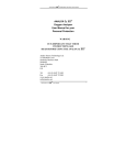
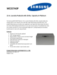
DRY AIR SYSTEMS, INC.
2655 Metro Boulevard
Maryland Heights, Missouri 63043
(314) 344-1114
fax (314) 344-0677
HD SERIES DRIERS
1
TABLE OF CONTENTS
WHY AN AIR DRYER
3
WHAT IS A DESICCANT AIR DRYER
3
Desiccant Air Dryer General Description
3
Theory of Desiccant Operation
Charge Cycle
Regeneration Cycle
4
4
4
INSTALLATION INSTRUCTIONS
6
HD2 (10 H.P compressors or less)
6
HD3-HD?? (above 10 H.P compressor)
7
REPLACEMENT SERVICE COMPONENTS PROCEDURE
8
6002K-002 Inlet Valve
8
6002K-001 Purge Valve
9
6002K-003 Desiccant Canister
11
6009X-010 Control Valve (HD2 only)
12
6009X-011 Timer (HD2 only)
13
TESTING THE UNIT
13
DRAWINGS
14
WARRANTY
15
2
WHY AN AIR DRYER
Compressor
HP
25
50
100
250
500
1000
2000
Total Inlet
Cu. Ft.
72,000
144,000
288,000
720,000
1,440,000
2,880,000
5,760,000
Gallons of
Water
13.6
27.2
54.3
135.8
271.7
543.4
1,086.60
All air systems trap and contain water
moisture and contaminants.
The chart
illustrates water accumulation during a
12-hour period. Moisture in compressed
air systems unchecked harms or destroys
delicate pneumatic controls. Water and
contamination
shortens
their
life
expectancy, reduces reservoir capacity
and affects compressor duty cycles.
Dry Air Systems offers air drying systems that improve overall system reliability and its related
pneumatic controls and devices. The HD series of air dryers are designed for continuous
desiccant regeneration with less than 7% of air required for regeneration. Operational cost
related to the air drying systems is less than a 75-watt light bulb.
These drying systems offer designs with:
•
•
•
•
Ease of installation
Expansion capabilities
Particulate filtration
Pressure dew point of –40 Fahrenheit
WHAT IS A DESICCANT AIR DRYER
Desiccant Air Dryer General
Description
The MVP series of air dryers are models
designed to mount vertically after the
compressor air reservoir. HD air dryer
systems receive warm compressed air
that cools, dry and filter contaminates
from compressed air before distribution
to air systems. Their designs reduce the
build up of dirt and moisture protecting
complete air systems, pneumatic tools
and spray paint booths.
3
HD air systems adapt to air compressors from 3HP up to multiple air compressor systems. Each
dryer within a specific system incorporates four pounds of desiccant. A precise continuous
regeneration cycle is accomplished without disrupting airflow ensuring a constant cleansing of
both the desiccant drying bed and internal filtration.
All HD air dryers are constructed of a lightweight aluminum and steel design housing a unique
spin-off cartridge. Below the cartridge are four ports: 1) inlet, 2) outlet, 3) control and 4) purge
port. Each port has a specific function. The inlet port receives contaminated air from the air
compressor. Outlet port directs clean dry air to the air system with a dual function of controlling
the regeneration flow rate. Control port receives an air signal from either a MLT (Micro Logic
Timer) allowing for the expulsion of water and contaminates through the dryers purge port.
Theory of Desiccant Operation
Charge Cycle
Compressed air enters the air dryer through the inlet port. As
the warm air enters the dryer system the air expands; oil and
water vapor condense, and accumulate in the sump. The air is
directed into a desiccant cartridge passing through a series of
internal filters and a cloth bag removing contaminates. Air
vapor continues to condense as air travels to the desiccant bed
that holds water under pressure. The clean dry air is then
directed to the air system through the outlet port.
Regeneration Cycle
Dryers systematically regenerate when control signals are
received from either the MLT by temporarily removing a single dryer
off line to begin the regeneration process. An air pressure signal
received from the MLT opens the purge valve and closes the air
dryer’s inlet and regeneration valves. This action causes a sudden
discharge of air through the exhaust port of the dryer. These valves
react to air pressure when an air dryer purge port opens. With the
inlet valve closed, the regeneration valve is in position to control a
timed pressurized back flow of filtered dried air that reenters the
desiccant cartridge. During the regeneration cycle, the desiccant bed
is depressurized allowing the removal of accumulated moisture from
desiccant bed, back flushing and cleaning filters expelling
contaminants out the dryers purge port.
This completes the
regeneration cycle.
MLT’s with their specified time intervals close the air dryer purge valve that reacts to the
evacuation of air pressure through the exhaust (EXH) port-controlling device.
4
Dry Air Systems, Inc. offers air drying systems to meet the unique requirements from complete
plant operation to single units for small or isolated application within an air system.
HD2
HD6
Dry Air Systems Inc.
2655 Metro Boulevard
Maryland Heights, Missouri 63043
(314) 344-1114
fax (314) 344-0677
email: [email protected]
5
INSTALLATION INSTRUCTIONS
HD2 (10 H.P compressors or less)
1. Inspect air compressor lines and fittings for air leaks.
1.1. Repair any air leaks. Replace any damaged lines or components
2. Drain all air system pressure
3. Locate mounting on wall and mark holes
3.1. Note: Desiccant canisters may be removed for easier installation
3.2. Note: Dryers are installed in the vertical position only (canisters up)
4. Mount air dryer system. Install mounting hardware as necessary
5. Connect air line from compressor reservoir to manifold inlet (bottom) of dryer system.
5.1. It is recommended to install a by-pass system for ease of servicing air dryer system
5.2. Note: 2 3/4"npt ports are available for both inlet and outlet. Factory installed plugs may
be removed from top and bottom of manifold and be replaced onto front of manifold to
facilitate better pipe/hose routing.
6. Connect air line from air dryer manifold (top) to air system
7. Plug MLT timer (6009X-010) into grounded and surge protected 110-volt receptacle
8. Restart air compressor and check for leaks
Installation Requirements
Dryer system requires at least 80 psi to operate MLT valve
Thread sealant must be used on all air connections
Dryers are installed in a vertical position only (Canisters up)
Hoses may be attached to exhaust ports to direct water drainage
Dryers cycle every 4 minutes
6
HD3-HD?? (above 10 H.P compressor)
1. Inspect air compressor lines and fittings for air leaks.
1.1. Repair any air leaks. Replace any damaged lines or components
2. Drain all air system pressure
3. Locate mounting on floor or wall and mark holes
3.1. Note: Desiccant canisters may be removed for easier installation
3.2. Note: Limited adjustment exists left to right by loosening 5/16 SHCS on drier manifold
3.3. Note: Brackets are shipped in floor mount position but may be moved to bolt to bottom
of manifold (as shown below) if wall mount is desirable
3.4. Note: Dryers are installed in the vertical position only (canisters up)
4. Mount air dryer system. Install mounting hardware as necessary
5. Connect air line from compressor reservoir to manifold inlet (bottom)
5.1. It is recommended to install a by-pass system for ease of servicing air dryer system
6. Connect air line from air dryer manifold outlet (top)
7. Hook up electrical power
7.1. If unit is supplied with a standard control box, there will be a wall mount dc transformer
which needs to be both plugged into the wall as well as into 5/16 dia female plug in
bottom of control box
7.2. If unit is shipped with an industrial power supply, a hole must be drilled into the control
box and 120vac brought to L1 & L2 terminal points – use adequate protection from
potential live electrical circuits!
8. Restart air compressor and check for leaks
Installation Requirements
Dryer system requires at least 80 psi to operate solenoid valves
Thread sealant must be used on all air connections
Dryers are installed in a vertical position only (Canisters up)
Hoses may be attached to exhaust ports to direct water drainage
Dryers cycle every 40 seconds
7
REPLACEMENT SERVICE COMPONENTS PROCEDURE
6002K-002 Inlet Valve
Installation Precautions
1. Stop compressor when working on air systems. Never connect or disconnect a hose or line
containing air pressure. Never remove a component or a pipe plug unless you are certain all
system air pressure has been exhausted.
2. Always wear safety glasses when working with air pressure. Never look directly into air dryer
ports.
3. Never exceed recommended working air pressure.
4. Never attempt to disassemble an air dryer until you have read and understood all recommended
procedures. Use only proper tools and observe all precautions pertaining to the use of those tools.
CAUTION: AIR DRYERS EXHAUST AT HIGH PRESSURE.
PROTECTIVE EYEWEAR SHOULD BE WORN WHILE SERVICING.
1. Exhaust/drain air system to zero PSI. If air dryer by-pass was installed, open/close valves as
necessary and drain air dryer unit by removing signal line from dryer outlet manifold (1/4” line)
2. Disconnect purge valve (PV-1) ¼” air line from dryer to be serviced.
3. Remove air dryer (6002A-001) from manifold by removing 4 5/16-18 SHCS.
4. Remove air dryer manifold mount pla te (6003D-003) by removing 4 #10-32 SHCS.
5. Remove 8 bolts from bottom cap assembly, remove cap and discard gasket.
6. Remove inlet valve nut, valve stop, valve, spring and discard.
7. Clean cavity area thoroughly.
8. Generously coat (with 6002X-005 silicone grease only) the 2 (small) o-rings surfaces and install
on piston. Carefully install valve and spring in cavity with tapered side up.
8
9. Place valve stop on top of valve with concave side down.
10. Lube large o-ring and place on nut. Install flat seal into nut.
11. Install nut and tighten to 50 ft. lb.
12. Place gasket on bottom cap. Locate bottom cap with inlet port directly below outlet port.
13. Re-assemble unit following steps (in reverse) 5 thru 1.
6002K-001 Purge Valve
Installation Precautions
1. Stop compressor when working on air systems. Never connect or disconnect a hose or line containing
air pressure. Never remove a component or a pipe plug unless you are certain all system air pressure
has been exhausted.
2. Always wear safety glasses when working with air pressure. Never look directly into air dryer ports.
3. Never exceed recommended working air pressure.
4. Never attempt to disassemble an air dryer until you have read and understood all recommended
procedures. Use only proper tools and observe all precautions pertaining to the use of those tools.
CAUTION: AIR DRYERS EXHAUST AT HIGH PRESSURE.
PROTECTIVE EYEWEAR SHOULD BE WORN WHILE SERVICING.
9
1. Exhaust/drain air system to zero PSI. If air dryer by-pass was installed, open/close valves as necessary
and drain air dryer unit by removing signal line from dryer outlet manifold (1/4” line)
2. Disconnect purge valve (PV-1) ¼” air line from dryer to be serviced.
3. Remove air dryer (6002A-001) from manifold by removing 4 5/16-18 SHCS.
4. Remove air dryer manifold mount plate (6003D-003) by removing 4 #10-32 SHCS.
5. Remove 2 1/4-20 SHCS from adapter (6003D-002).
6. Remove adapter & purge valve operator /seal retainer (6002X-020).
7. Remove seal retainer, purge valve assembly, 4 O-rings and screen. Check to be sure all components
are removed and discarded.
8. Clean purge valve cavity.
NOTE: Excessive accumulation of oil in the air dryer purge valve indicates compressor may require
service. Disassemble entire air dryer and check for blockage within the valve cavities, safety
valve and bottom cap cavity. Clean as necessary.
6. Remove all (3) old o-rings from center portion of bolt-on seal retainer. Apply a light coating of
(6003X-005) grease on first two new o-rings (1.362 x 10³). Install new o-rings on seal retainer.
Apply a light coating of grease on the other new O-ring (1.174 x.103). Install on end of seal retainer
NOTE: When removing old o-rings be careful not to damage O-ring seats.
7. Apply a light coating of grease to the threads of seal 2 seal retainer bolts.
8. Install new filter screen in purge valve cavity (closed end first).
9. Apply a light coating of (6003X-005) grease to O-ring seat on new purge valve end (1/2 ball end) and
install new O-ring (1.364 x.070).
10. Align valve assembly exhaust port with bottom cap exhaust port and install valve assembly.
NOTE: Be careful not to dislodge O-ring during valve installation.
11. Reassemble by following steps (in reverse) 6 thru 1.
10
6002K-003 Desiccant Canister
CAUTION: DO NOT OVER TIGHTEN CARTRIDGE.
HAND TIGHTEN UNTIL GASKET CONTACTS ADAPTOR
PLATE AND TURN ADDITIONAL 1/2 TURN ONLY!
Installation Precautions
1. Stop compressor when working on air systems. Never connect or disconnect a hose or line containing
air pressure. Never remove a component or a pipe plug unless you are certain all system air pressure
has been exhausted.
2. Always wear safety glasses when working with air pressure. Never look directly into air dryer ports.
3. Never exceed recommended working air pressure.
4. Never attempt to disassemble an air dryer until you have read and understood all recommended
procedures. Use only proper tools and observe all precautions pertaining to the use of those tools.
CAUTION: AIR DRYERS EXHAUST AT HIGH PRESSURE.
PROTECTIVE EYEWEAR SHOULD BE WORN WHILE SERVICING.
Service Instructions
1.
2.
3.
4.
Whenever servicing the air dryer, clean and inspect entire unit for any external damage.
Remove old cartridge (turn counter-clockwise).
Clean dirt/oil from top surface of adaptor plate and threaded stud
Remove old O-ring from threaded adaptor.
NOTE: Excessive accumulation of oil in the air dryer or air
dryer cartridge indicates the compressor may require
service. Disassemble entire unit and check for
blockage within the valve cavities, safety valve and
bottom cap cavity. Drain, clean and replace worn
components as necessary.
5. Lubricate new O-ring and install on threaded adaptor.
6. Lubricate the gasket on the new desiccant cartridge.
7. Thread new cartridge onto adaptor (turn clockwise)
DO NOT CROSS THREAD
NOTE: When gasket contacts adaptor plate, tighten 1/2 turn.
DO NOT OVER TIGHTEN or cartridge could be extremely
difficult to remove.
11
6009X-010 Control Valve (HD2 only)
Installation Precautions
1. Stop compressor when working on air systems. Never connect or disconnect a hose or line containing
air pressure. Never remove a component or a pipe plug unless you are certain all system air pressure has
been exhausted.
2. Always wear safety glasses when working with air pressure. Never look directly into air dryer ports.
3. Never exceed recommended working air pressure.
4. Never attempt to disassemble an air dryer until you have read and understood all recommended
procedures. Use only proper tools and observe all precautions pertaining to the use of those tools.
CAUTION: AIR DRYERS EXHAUST AT HIGH PRESSURE.
PROTECTIVE EYEWEAR SHOULD BE WORN WHILE SERVICING.
1. Exhaust/drain air system to zero PSI. If air dryer by-pass was installed, open/close valves as
necessary and drain air dryer unit by removing signal line from dryer outlet manifold (1/4” line).
2. Remove 1/4” air line from 3 locations at 6009X-010 control valve 6009X-005 tube fittings.
3. Remove 6009X-010C retaining nut from control valve and drop solenoid/timer from unit.
Remove timer from solenoid with 1 screw.
4. Remove 6009X-007 #8-32 screws at 3 locations connecting control valve to HD2 manifold body
and drop valve.
12
5. Remove fittings from control valve, verify serviceability of fittings and exhaust mufflers.
Replace as necessary. It is recommended that (2) 6009X-006 exhaust mufflers be replaced with
valve.
6. Install fittings and mufflers on valve and replace in reverse order.
6009X-011 Timer (HD2 only)
1. Remove 6009X-010C retaining nut from control valve and drop solenoid/timer from unit.
Remove timer from solenoid with 1 screw.
2. Replace timer and install in reverse order.
TESTING THE UNIT
1. Check air tanks for accumulated moisture and drain as required.
2. Start air compressor and allow system pressure to build until cut out pressure.
3. Check all connections for air leaks.
NOTE: After air dryers exhausts, air will continue to bleed out of exhaust port until regeneration timed
cycles is completed
4. NOTE: A soap solution works very well for locating leaks.
13
DRAWINGS
The following drawings are supplied with this manual:
6001A-001 thru –006
6002A-001, 002
6003A-001, 002
6005A-001
6007A-001, 002
6007E-001, 002
6007M-001
6009A-001, 002
6016A-001
XL76
Drawings can be beneficial when referencing maintenance procedures in this manual. System
troubleshooting and replacement parts procurement can also be facilitated with the following
drawings:
14
WARRANTY
For the period of one (1) year, Seller’s sole obligation and Buyer’s sole and exclusive remedy for
any defect Product(s) shall be Seller’s reimbursement of the “Warranty Expense”. In addition
Seller’s obligation for the Product(s) which are not in conformance with the Seller’s warranty shall
be further limited to those product(s) which are promptly returned to Seller after discovery of any
alleged defect with Freight prepaid to the warehouse designated by the Seller’s representative and
which Product(s) are found by Seller (in the exercise of its sole and exclusive judgment made by
Seller experienced and highly skilled personnel) to have been defective in accordance with the
warranty. Seller will in no event be liable for any consequential special or contingent damages or
expenses arising directly or indirectly from any defects in its goods or from the use thereof, nor is
any other person authorized to assume for the seller any such liability or any contrary
representations or warranty on behalf of the Seller.
In no event shall the Seller be obligated under Seller’s agreement or otherwise in any manner
whatsoever for normal wear and tear of any product(s) which in the seller’s sole and exclusive
determination have been subjected to accident, abuse, misapplication, improper repair or alteration
or maintenance, neglect, excessive operating conditions or for defects resulting from Buyer’s
specifications or designs, or otherwise caused by the Buyer, including without limitation defects
resulting from Buyer’s manufacture, distribution, sale or promotion of its own product.
Seller expressly disclaims any implied or expressed warranty of fitness for a particular purpose. It
is understood that such products are warranted to be fit for their ordinary intended use.
Dry Air Systems, Inc.
2655 Metro Boulevard
Maryland Heights, Missouri 63043
Telephone: 314 344-1114
Fax: 314 344-0677
www.dry-air-systems.com
15