1
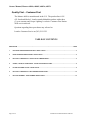
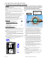
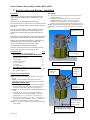
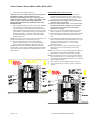
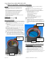
Owners Manual, Monaco 6000A, 6000N, 6002A, 6002N
MONACO 6000
OWNERS
MANUAL
Page 1 of 12
9700 B Owners Manual Monaco 6000.doc
Owners Manual, Monaco 6000A, 6000N, 6002A, 6002N
Quality First – Customer First
The Monaco 6000 is manufactured in the U.S. The product line is UL/
cUL listed and labeled. Lumiére stands behind the product with a three
(3) year warranty and Cooper Lighting’s exclusive Customer First NationWide service network.
Questions regarding these procedures may referred to:
Lumiére Customer Service at (303) 393-1522.
TABLE OF CONTENTS
DESCRIPTION ...........................................................................................................................................................................PAGE
1.
NON DRIVE-OVER RECESSED HOUSING - INSTALLATION .............................................................................................3
2.
DRIVE-OVER RECESSED HOUSING - INSTALLATION ......................................................................................................4
3.
BALLAST & LAMP MODULE – INSTALLATION & MAINTENANCE ...................................................................................6
4.
GUARD, LOUVER, & GLARE SHIELD - INSTALLATION INSTRUCTIONS.........................................................................8
5.
FILTERS & THERMAL GLASS - INSTALLATION .................................................................................................................9
6.
BALLAST & LAMP MODULE - REPLACEMENT INSTRUCTIONS ....................................................................................10
7.
BALLAST ASSEMBLY – REPLACEMENT INSTRUCTIONS ..............................................................................................12
Page 2 of 12
9700 B Owners Manual Monaco 6000.doc
Owners Manual, Monaco 6000A, 6000N, 6002A, 6002N
1. Non Drive-Over Recessed Housing - Installation
WARNING!
NOTE: Four (4) screws will be visible on outer trim ring when
TURN OFF POWER BEFORE INSTALLATION, MAINTENANCE, installation is complete. The orientation of screws is important,
RELAMPING, OR SERVICING.
orient housing as shown below. Trim ring screws will be located
at 12 o’clock, 3 o’clock, 6 o’clock and 9 o’clock, relative to
FIXTURE IS DESIGNED FOR IN-GROUND UP-LIGHT
center of side-mounted wiring compartment. Wiring
INSTALLATION ONLY. DO NOT INSTALL IN CEILINGS OR
compartment should be perpendicular to the wall or illuminated
WALLS.
surface.
FIXTURE IS SUITABLE FOR IN-GRADE INTALL IN SOIL,
THREADED HOLES
CONCRETE, BRICK, OR NON-COMBUSTIBLE MASONRY
FOR TRIM RING
MATERIALS ONLY.
SCREWS, 4X
FIXTURE MUST NOT COME INTO CONTACT WITH WOOD OR
WALL
OTHER COMBUSTIBLE MATERIALS OR SURFACES.
BARRICADE AND MARK OPEN HOLES, TRENCHES, OR
FIXTURES UNTIL INSTALLATION IS COMPLETE.
70 WATTS OR BELOW WITH TRL OPTION ARE
RECOMMENDED FOR PEDESTRIAN AREAS
FIXTURE MUST BE INSTALLED IN ACCORDANCE WITH
LOCAL & NATIONAL ELECTRICAL CODES.
MATERIAL LIST
`
QTY
Recessed Housing, Monaco 6000/6002
1
The following materials supplied by others
½” Threaded Rod, 36” Sections
3
½”-13 Nut
3
2” Fender Washer
3
Free drain material (CBR of 20 or greater) .
6 yards
¾” NPT Connector
1
INSTALLATION PROCEDURE
Models 6000A, 6000N, 6002A & 6002N
NOTE: These instructions are for non drive-over application. Driveover application require kit # 6000-DSB and Installation Sheet
#9702.
NOTE: Soil must be prepared as specified by civil or soils engineer.
NOTE: Compact trenches to 90% relative compaction and comply
with pavement design specifications.
1) Select threaded ports in side-mounted wiring compartment for
power in. Knock out selected plugs, being careful not to damage
threads in port walls.
2) Dig a hole at least 18 inch diameter at base and 38 inches deep.
NOTE: ½” threaded rod will be used to stabilize housing. Cut three
(3) lengths of ½” threaded rod (provided by others) to
approximately 36”.
3) Lower fixture housing into hole.
90°
4)
With housing oriented in hole, locate three lengths of threaded
rod in integral flange slots on outer edge of housing.
Temporarily thread two nuts to top of threaded rod to protect
threads. Tap top of threaded rods to get them started in
ground. Remove housing from hole. Continue driving rods
straight into ground until 6 inches below ground level.
5) Fill bottom of hole with 18 inches of drainage material
(provided by others). Material must be “select” free draining
material with a California Bearing Ratio (CBR) of 20, or
greater.
NOTE: Water will collect and drain through bottom of fixture
housing. Verify drainage through fixture bottom will not
adversely affect hardscape around fixture or hardscape base.
6) Lower the fixture housing into hole with threaded rods in
integral slots. Add or remove drainage material beneath
housing until top edge of housing is level with finished
surface. Install concrete pour cover (if provided) securely on
top of housing to prevent debris from entering. Level and
secure housing to threaded rods using nuts and washers
(provided by others). See figure.
7) Run incoming power lines and connect conduit to selected
ports in mounted wiring compartment using ¾” NPT
connectors (provided by others). Access wiring compartment
by twisting top cover counter-clockwise.
NOTE: Conduit connections must be sealed with waterproof
material to prevent water from leaking into wiring
compartment.
NOTE: Leave at least 6” of wire extending from conduit, for later
connection with lamp module/ballast assembly.
8) Back-fill hole and compress material. Finish surface material
so that it is even with top.
9) Finish surface material so that it is even with top edge of
fixture housing.
Page 3 of 12
9700 B Owners Manual Monaco 6000.doc
Owners Manual, Monaco 6000A, 6000N, 6002A, 6002N
2. Drive-Over Recessed Housing - Installation
WARNING!
TURN OFF ALL POWER TO FIXTURE BEFORE INITIAL
INSTALLATION, MAINTENANCE, RELAMPING, AND
SERVICING.
THIS FIXTURE IS DESIGNED FOR IN-GROUND
INSTALLATION ONLY FOR USE AS AN UPLIGHT. DO NOT
INSTALL IN CEILINGS OR IN VERTICAL SURFACES SUCH
AS WALLS.
SUITABLE FOR IN-GROUND DIRECT BURIAL, OR FOR
INSTALLATION IN POURED CONCRETE, BRICK, OR
OTHER NON-COMBUSTIBLE MASONRY MATERIALS
ONLY.
HOLE PREP
4) Dig a hole that is at least 18 inches in diameter at the base
and 38 inches deep.
5) Included in the installation kit are six 2 foot sections of
threaded rod and three couplers. Join two sections of
threaded rod with a coupler to make a 4 ft threaded rod
assembly. Do the same with the other threaded rod sections.
NOTE: The threaded rod assemblies will be pounded into the soil
and attached to the housing to stabilize the fixture for the cement
pour.
Drive-over brackets
Qty - 4
FIXTURE MUST NOT COME INTO CONTACT WITH WOOD
OR OTHER COMBUSTIBLE MATERIALS OR SURFACES.
BARRICADE AND MARK OPEN HOLES, TRENCHES, OR
FIXTURES UNTIL INSTALLATION IS COMPLETE.
70 WATTS OR BELOW WITH TRL OPTION ARE
RECOMMENDED FOR PEDESTRIAN AREAS
FIXTURE TO BE INSTALLED IN ACCORDANCE WITH
LOCAL AND NATIONAL ELECTRICAL CODES.
MATERIAL LIST
QTY
Recessed Housing, Monaco 6000/6002
1
Drive-Over Kit # 6000-DSB (Must Be Ordered)
Drive-Over Brackets
4
Threaded Rod, 2 ft Sections
6
Anchor Bolts
`
6
Threaded Rod Couplers
3
½”-13 x 1” Bolts
4
½”-13 Nuts
29
2” Fender Washer
3
Other Material Required-Provided by others
Free drain material (CBR of 20 or greater), approx.0.6 yard
One ¾” NPT Connector
1
INSTALLATION PROCEDURE
MONACO 6000 AND 6002
NOTE: Soil must be prepared as specified by a civil or soils
engineer.
NOTE: Trenches should be compacted to 90% relative
compaction and comply with pavement design specifications.
RECESSED HOUSING PREP
1) Determine which of the four (4) threaded ports in the sidemounted wiring compartment will be used to run power to
the fixture. Knock out the plug in the required ports.
CAUTION: Be careful not to damage the threads inside the port
walls.
2) Assemble the four (4) drive-over brackets around the
recessed housing, as shown in the diagram. Connect the
brackets with ½”-13 x 1” bolts and ½”-13 nuts (Qty 8).
3) Attach six (6) anchor bolts, ½-13 x 8” x 3” to the drive over
brackets as shown in the diagram. Attach ½-13 nuts to the
anchor bolts approximately 1” above the bracket.
NOTE: The “L” section of the bolt must be facing out as shown
in the diagram.
½ x 13 x 1” bolts-qty 8
½ x 13 nuts-Qty 8
Drive-over Bracket Assembly
½-13 nut on
top and
bottom of
bracket
2” fender
washer and
½-13 nut
Anchor bolts and
nuts – qty 6,
L must face out
Threaded rod-join
two sections, with
coupler, to make
one 4 ft section
Complete Recessed Housing as
it will appear in the ground
Page 4 of 12
9700 B Owners Manual Monaco 6000.doc
Owners Manual, Monaco 6000A, 6000N, 6002A, 6002N
8) Lower the fixture housing into the hole.
NOTE: Four (4) screws will be visible on outer trim ring when
installation is complete. The orientation of screws is
important, orient housing shown on pg 3. Trim ring screws
will be located at 12 o’clock, 3 o’clock, 6 o’clock and 9 o’clock,
relative to center of side-mounted wiring compartment.
Wiring compartment should be perpendicular to the wall or
illuminated surface.
9) With the housing setting in the hole, locate the three threaded
rod assemblies in the integral flange slots along the outer
edge of the housing. Temporarily attach two nuts to the top
of the threaded rods to protect the threads. Tap the top of the
rod assemblies to get them started in the ground. Remove the
housing from the hole. Continue driving the rods straight
into the ground until they are about 1 inch below the final
finished surface level.
NOTE: Do not drive rods too deep. If they are too deep they will
not reach the housing drive-over bracket at a later step.
10 Fill the bottom of the hole with 18 inches of drainage
material. Material shall be “select” free draining material
with a California Bearing Ration (CBR) of 20 or greater.
NOTE: Water will collect and drain through the bottom of the
fixture housing. Verify that water drainage through fixture bottom
will not adversely affect hardscape surrounding the fixture, or the
hardscape base.
Page 5 of 12
RECESSED HOUSING INSTALLATION
11) Lower the fixture housing into the hole, with the three
threaded rods located in the flange slots. Add or remove
drainage material beneath the housing, until the top edge of
the housing is at the desired finished surface level.
12) Locate the top of the threaded rods in the appropriate
holes of the drive over brackets.
13) Place a 2” fender washer and ½-13 nut on each of the
threaded rods as shown in diagram. Run the washer
and nut down until it contacts the housing flange.
Tighten the nut snuggly.
14) Place a ½-13 nut on each of the threaded rods, on top and
bottom of the drive-over brackets as shown in diagram.
15) The threaded rods can be used to level the fixture. Adjust the
nuts on top and bottom of the brackets until the fixture is
level.
16) Run incoming power lines and connect conduit to selected
ports in the side-mounted wiring compartment using ¾” NPT
connectors (provided by others). Access the wiring
compartment by removing the cover. Twist counterclockwise to remove.
NOTE: Conduit connections must be sealed with waterproof
material to prevent water from leaking into the wiring
compartment.
NOTE: Leave at least 6” of wire extending from the conduit, for
later connection with the lamp module/ballast assembly.
17) Backfill the hole with soil as shown on page 5 or page 6.
NOTE: Final surface layer may be concrete or another material
such as asphalt, pavers, ect… If final surface is not concrete,
concrete must be applied below the final drive over surface as
shown in diagram on page 6.
18) Pour concrete as shown in diagram on page 5 or page 6.
19) Apply top surface layer, as shown on page 6, if other than
concrete.
9700 B Owners Manual Monaco 6000.doc
Owners Manual, Monaco 6000A, 6000N, 6002A, 6002N
3. Ballast & Lamp Module – Installation & Maintenance
WARNING!
TURN OFF ALL POWER TO FIXTURE BEFORE INITIAL
INSTALLATION, MAINTENANCE, RELAMPING, AND
SERVICING.
DO NOT OVERTIGHTEN CAPTIVE SCREWS ON OUTER
LENS! SET POWER DRIVERS TO LOWEST SETTING.
THIS IS IMPORTANT TO AVOID PART DAMAGE.
70 WATT OR BELOW WITH TRL OPTION ARE
RECOMMENDED FOR PEDESTRIAN AREAS
FIXTURE TO BE INSTALLED IN ACCORDANCE W/ LOCAL
AND NATIONAL CODES
MATERIAL LIST
QTY
Ballast and Lamp Module Assembly 1
Submersible Wire Nuts (included)
3
INSTALLATION PROCEDURE
NOTE: Housing assembly must be properly installed in ground prior
to ballast and lamp module installation. Refer to Recessed Housing
Installation Sheet # 9701, 9702, or 9703.
NOTE: If a concrete pour cover is attached to housing, remove and
discard cover.
1) If side mounted wiring compartment on housing is accessible,
remove cover from compartment. (Twist counter-clockwise to
remove.)
NOTE: If wiring compartment is not accessible, fixture will need to
be wired from inside of recessed housing.
NOTE: Remove any debris in bottom of housing that may interfere
with installation of ballast assembly and sealed lamp module.
2) Place ballast assembly in bottom of housing with wires facing up.
NOTE: There is no specific orientation for ballast assembly.
3) Set sealed lamp module assembly on ground next to housing.
4) There is a plastic strain relief attached to free wires coming off
ballast assembly. Attach strain relief to housing by removing nut
from stud, attaching strain relief, and reattaching nut. See Figure
1.
6)
Connect three color coded wires from ballast assembly to
incoming power wires.
NOTE: Wires must be connected using submersible wire nuts
provided.
NOTE: There are two green ground wires, one from Ballast
Assembly and one that goes to Lamp Housing. Both must be
wire nut attached to incoming power ground.
7) Connect wires as follows:
Strip wires from incoming power to ½”.
Align frayed strands or conductors.
Do not pre-twist wires.
Twist stranded wires slightly.
Insert wires together through sealant into connector.
Hold wires firmly and twist connector onto wires.
NOTE: Do not twist wire nuts too hard.
NOTE: Do not reuse wire nuts.
8) Carefully insert wires with wire nuts into side mounted wiring
compartment. Replace top cover on wiring compartment.
9) Carefully place lamp module into housing. Align the two notches
in lamp assembly hanging frame with two pins in housing. See
Figure 2.
Lamp angle adjust
screw
Attach strain relief
from ballast
assembly here
Align notches in lamp
module hanging frame
over these pins
Figure 2
LAMP ANGLE ADJUSTMENT – FOR MODELS 6000A AND
6002A ONLY.
(FOR MODELS 6000N AND 6002N, GO TO STEP 12)
10) Adjust angle of lamp by inserting a hex wrench into the
adjustment screw, as shown in Figure 2, and turning screw
clockwise or counter-clockwise until lamp is at desired angle.
Maximum tilt is 15 degrees from vertical.
11) After desired angle has been reached, the light direct may be
rotated 360 degrees to orient the light. When orientation has been
achieved, tighten slotted set screw on lens collar as shown in
Figure 3.
Figure 1
5)
Route wires through opening in side mounted wiring
compartment or out of top of housing.
Page 6 of 12
9700 B Owners Manual Monaco 6000.doc
Owners Manual, Monaco 6000A, 6000N, 6002A, 6002N
Slotted screw
locks/unlocks orientation
lamp adjustment
Loosen this screw
to remove sealing
clamp
Lamp module
sealing clamp
Figure 3
INSTALL TRIM RING/LENS ASSEMBLY
12) Install trim ring/lens assembly by aligning four threaded holes
and attaching four socket head cap screws.
RELAMPING PROCEDURE
WARNING! TURN OFF ALL POWER TO FIXTURE BEFORE,
RELAMPING, MAINTENANCE AND SERVICING.
WARNING! RELAMP ONLY WITH SAME WATTAGE AND
TYPE OF LAMP ORIGINALLY SUPPLIED WITH FIXTURE.
SEE LABEL ON SIDE OF BALLAST BOX FOR CORRECT
INFORMATION.
13) Loosen trim ring/lens assembly by loosening four socket head cap
screws.
14) Pry trim ring/lens assembly off housing by inserting a flat head
screwdriver in side slots and turning.
15) Remove trim ring/lens assembly.
16) Lift sealed lamp module from housing assembly.
17) Remove lamp module sealing clamp by loosening screw on
clamp with a 3/16” Allen wrench. See Figure 4.
NOTE: Screw does not have to be removed
18) Remove lamp module sealing clamp by pulling it out and over
screw head. Then pull remainder of clamp free of assembly.
CAUTION: Do not bend clamp!
19) Remove optical accessory holder from top of lens.
20) Remove inner lens with rubber seal.
21) Replace lamp.
22) Verify that inside of lamp housing is clean and dry before
reassembly.
23) Verify that inner seal and lens are clean and dry before
reassembly.
24) Reassemble fixture in reverse order of disassembly.
Page 7 of 12
Figure 4
9700 B Owners Manual Monaco 6000.doc
Owners Manual, Monaco 6000A, 6000N, 6002A, 6002N
4. Guard, Louver, & Glare Shield - Installation Instructions
WARNING!
TURN OFF ALL POWER TO FIXTURE BEFORE INITIAL INSTALLATION, MAINTENANCE, RELAMPING, AND
SERVICING.
DO NOT OVERTIGHTEN CAPTIVE SCREWS ON OUTER LENS! SET POWER DRIVERS TO LOWEST SETTING. THIS IS
IMPORTANT TO AVOID PART DAMAGE.
THE MONACO 6000 AND 6002 FIXTURE IS DESIGNED FOR IN-GROUND INSTALLATION ONLY FOR USE AS AN
UPLIGHT. DO NOT INSTALL IN CEILINGS OR IN VERTICAL SURFACES SUCH AS WALLS.
SUITABLE FOR IN-GROUND DIRECT BURIAL, OR FOR INSTALLATION IN POURED CONCRETE, BRICK, OR OTHER
NON-COMBUSTIBLE MASONRY MATERIALS ONLY.
FIXTURE MUST NOT COME INTO CONTACT WITH WOOD OR OTHER COMBUSTIBLE MATERIALS OR SURFACES.
70 WATTS OR BELOW WITH TRL OPTION ARE RECOMMENDED FOR PEDESTRIAN AREAS
FIXTURE TO BE INSTALLED IN ACCORDANCE WITH LOCAL AND NATIONAL ELECTRICAL CODES.
MATERIAL LIST
Installed Monaco 6000 or 6002
Guard, Louver, or Glare Shield
Clamp Ring
Long Captive Screws
QTY
1
1
1
4
INSTALLATION INSTRUCTIONS
1.
2.
3.
4.
5.
Do not remove Clamp Ring from Guard, Louver, or Glare Shield because these are matched pairs.
Remove Outer Lens Assembly from top of fixture.
Remove four short captive screws from Outer Lens Assembly.
Reposition Outer Lens Assembly on top of fixture.
Look through trim ring holes and assure that they are aligned with holes in nut plate. (Note: This alignment is very critical with
accessory installation)
6. Place Accessory Assembly (Accessory with Clamp Ring Installed) on top of trim ring and align accessory to provide desired
shielding.
7. Align holes of accessory assembly with holes in Outer Lens Assembly.
8. Thread one long captive screw through accessory assembly, through trim ring, and into the nut plate. “DO NOT FULLY
TIGHTEN THE SCREW AT THIS POINT”
9. Thread remaining screws through accessory, through Outer Lens Assembly, and into the Nut Plate. “DO NOT FULLY
TIGHTEN THE SCREWS AT THIS POINT”.
10. After last screw is loosely installed, realign accessory to provide desired shield orientation. Gradually tighten the four screws. DO
NOT OVERTIGHTEN CAPTIVE SCREWS ON OUTER LENS! SET POWER DRIVERS TO LOWEST SETTING. THIS IS
IMPORTANT TO AVOID PART DAMAGE.
11. When re-lamping, removal of one of the captive screws may make it easier to align the Accessory/Outer Lens Assembly with the
Nut Plate. You may then loosen the remaining screws and remove trim ring with the Guard, Louver, or Shield.
Accessory Assembly
(Accessory with
Clamp Ring Installed)
Outer Lens
Assembly
Nut Plate
Page 8 of 12
9700 B Owners Manual Monaco 6000.doc
Owners Manual, Monaco 6000A, 6000N, 6002A, 6002N
5. Filters & Thermal Glass - Installation
WARNING!
70 WATTS OR BELOW WITH TRL OPTION ARE RECOMMENDED FOR PEDESTRIAN AREAS
INSTALLATION INSTRUCTIONS:
Up to three accessories may be installed.
The Internal Hex Cell Louver (LVR6), Temperature Reduction Lens (TRL), and Dichroic Filters are installed on top of Cast Bezel on inner
module assembly. It is recommended that they are installed in the following order:
Internal Hex Cell Louver (LVR6)
Linear Spread Lens (LSL)
Dichroic Filters
Temp Reduction Lens (TRL)
->
->
->
->
Above both the LSL, Dichroic, & TRL
Above the Dichroic or TRL
Above the TRL
At the lowest position
The Mount Spring is installed in the groove as shown above the accessories. It is not required when LVR6 is installed
Mount Spring
Installed Accessories
Cast Bezel
Page 9 of 12
9700 B Owners Manual Monaco 6000.doc
Owners Manual, Monaco 6000A, 6000N, 6002A, 6002N
6. Ballast & Lamp Module - Replacement Instructions
WARNING!
TURN OFF ALL POWER TO FIXTURE BEFORE
REPLACING BALLAST ASSEMBLY.
DO NOT OVERTIGHTEN CAPTIVE SCREWS ON THE
TRIM RING! SET POWER DRIVERS TO LOWEST
SETTING. THIS IS IMPORTANT TO AVOID DAMAGING
PARTS.
MATERIAL LIST
Ballast and Lamp Module Replacement Assembly
Submersible Wire Nuts (included)
3
Return address label
QTY
1
1
BALLAST AND LAMP MODULE REPLACEMENT
PROCEDURE
1) Loosen trim ring/lens assembly by loosening four socket
head cap screws.
2) Pry trim ring/lens assembly off housing by inserting a flat
head screwdriver in side slots and turning.
Remove trim ring/lens assembly.
4) Lift sealed lamp module from housing.
5) Disconnect ballast wires from incoming power by
removing wire nut connections in the
housing wiring box. (Discard wire nuts. New water-tight
water nuts, provided, must be used
for reconnection).
6) Disconnect ground wire from ballast to incoming power.
7) Lift ballast assembly out of the housing.
8) Disconnect strain relief from side of in-grade housing and
set the ballast to be replaced aside.
9) Unpack the new ballast/lamp module assembly and place
ballast in the housing with the wires
facing up.
NOTE: USE THE SAME BOX TO SEND A FAILED
BALLAST BACK TO LUMIERE FOR FAILURE
ANALYSIS. ALL RETURNS MUST BE
AUTHORIZED BY YOUR FIELD SERVICE
REPRESENTATIVE.
10) Set sealed lamp module assembly on the ground next to
housing.
11) There is a plastic strain relief attached to free wires
coming off ballast assembly. Attach strain relief to stud
of in-grade housing and reattach nut. See Figure 1.
12) Route wires through opening in side mounted wiring
compartment.
13) Connect the three color coded wires from ballast assembly to
incoming power wires.
NOTE: WIRES MUST BE CONNECTED USING THE
SUBMERSIBLE WATER-TIGHT WIRE NUTS
PROVIDED.
NOTE: THERE ARE TWO GREEN GROUND WIRES, ONE
FROM THE BALLAST ASSEMBLY AND ONE ON THE
HOUSING, WHICH MUST BE ATTACHED TO THE
INCOMING POWER GROUND.
14) Connect wires using water-tight wire nuts, as follows:
Strip wires from incoming power to ½”.
Align frayed strands or conductors.
Twist stranded wires slightly.
Insert wires together through sealant in wire nuts.
Hold wires firmly and twist wire nuts onto wires.
NOTE: Do not twist wire nuts too hard.
NOTE: Do not reuse wire nuts.
15) Carefully insert wires with wire nuts into side mounted
wiring compartment.
16) Carefully place lamp module into housing. Align two
notches in lamp module
hanging frame with two pins in the housing. See Figure 2.
Attach strain relief
from ballast
assembly here
Figure 1
Page 10 of 12
9700 B Owners Manual Monaco 6000.doc
Owners Manual, Monaco 6000A, 6000N, 6002A, 6002N
Lamp angle
adjust screw
Slotted screw
locks/unlocks
orientation lamp
adjustment
Figure 2
Align notches in
lamp module
hanging frame over
these pins
Figure 3
LAMP ANGLE ADJUSTMENT – FOR MODELS 6000A AND
6002A ONLY.
(FOR MODELS 6000N AND 6002N, GO TO STEP 12)
17) Adjust angle of lamp by inserting a hex wrench into the
adjustment screw, as shown in Figure 2, and turning screw
clockwise or counter-clockwise until lamp is at desired angle.
Maximum tilt is 15 degrees from vertical.
18) After desired angle has been reached, the light may be
rotated 360 degrees to orient the light. When orientation
has been achieved, tighten slotted set screw on lens collar as
shown in Figure 3.
Page 11 of 12
INSTALL TRIM RING/LENS ASSEMBLY
Install trim ring/lens assembly by aligning the four threaded
holes and attaching the four socket head cap screws. DO NOT
OVERTIGHTEN CAPTIVE SCREWS ON OUTER LENS!
SET POWER DRIVERS TO LOWEST SETTING. THIS IS
IMPORTANT TO AVOID PART DAMAGE.
RELAMPING PROCEDURE
WARNING! TURN OFF ALL POWER TO FIXTURE BEFORE,
RELAMPING, MAINTENANCE AND SERVICING.
WARNING! RELAMP ONLY WITH SAME WATTAGE AND
TYPE OF LAMP ORIGINALLY SUPPLIED WITH FIXTURE.
SEE LABEL ON SIDE OF BALLAST BOX FOR CORRECT
INFORMATION.
WARNING! DO NOT OVERTIGHTEN CAPTIVE SCREWS ON
OUTER LENS! SET POWER DRIVERS TO LOWEST
SETTING. THIS IS IMPORTANT TO AVOID PART
DAMAGE.
19) Loosen trim ring/lens assembly by loosening the four socket head
cap screws.
20) Pry trim ring/lens assembly off housing by inserting a flat head
screwdriver in side slots and turning.
9700 B Owners Manual Monaco 6000.doc
Owners Manual, Monaco 6000A, 6000N, 6002A, 6002N
7. Ballast Assembly – Replacement Instructions
WARNING!
TURN OFF ALL POWER TO FIXTURE BEFORE
REPLACING THE BALLAST ASSEMBLY.
DO NOT OVERTIGHTEN CAPTIVE SCREWS ON OUTER
LENS! SET POWER DRIVERS TO LOWEST SETTING.
THIS IS IMPORTANT TO AVOID PART DAMAGE.
ORDER BALLAST WITH THE DESIRED WATTAGE AND
VOLTAGE AS SPECIFIED ON BALLAST BOX LABEL.
NOTE: USE THE SAME BOX TO SEND THE FAILED
BALLAST BACK TO LUMIERE FOR FAILURE
ANALYSIS. ALL RETURNS MUST BE AUTHORIZED
BY YOUR FIELD SERVICE REPRESENTATIVE.
14) Insert mesh covered lamp wires downward through handle of
potted ballast assembly and slide plastic strain relief over
wires and mesh and tighten down on mesh and wire about 2
inches from end.
IN THIS PROCEDURE, YOU WILL REMOVE THE OLD
BALLAST AND ATTACH A REPLACEMENT.
MATERIAL LIST
Ballast Replacement Assembly
Submersible Wire Nuts
Plastic Strain Relief
Return address label
QTY
1
6
1
1
BALLAST REPLACEMENT PROCEDURE
1)
2)
3)
4)
5)
6)
7)
8)
9)
10)
11)
12)
13)
Loosen trim ring/lens assembly by loosening the four socket
head cap screws.
Pry trim ring/lens assembly off housing by inserting a flat
head screwdriver in side slots and turning.
Remove trim ring/lens assembly.
Lift sealed lamp assembly from housing.
Disconnect ballast wires from incoming power by removing
wire nut connections in housing wiring box. (Discard wire
nuts. New water-tight water nuts, provided, must be used for
reconnection).
Disconnect ground wire from ballast to incoming power.
Disconnect ballast wire strain relief from the side of inground housing.
Lift ballast assembly out of housing.
Cut plastic tie wrap attaching the green, blue, and white
wires coming out of the ballast box.
Cut through black mesh and wires that lead from ballast
assembly to lamp assembly, about 2” above the ballast box.
On lamp assembly, trim black mesh so that it is 1” shorter
than the wires inside it.
Strip green, blue, and white wires on lamp assembly to ½”.
Unpack new ballast kit. (plastic strain relief not shown)
ROUTE MESH
COVERED LAMP
WIRES DOWN
THROUGH
HANDLE
15) Connect the three SHORT color coded wires (green, blue,
and white) from the new ballast replacement assembly to
lamp assembly as follows: Twist stranded wires slightly
Insert wires together into new sealant wire nuts (provided)
Hold wires firmly and twist connector onto wires
NOTE: Do not twist wire nuts too hard
NOTE: Do not reuse wire nuts
INSTALL
PLASTIC STRAIN
RELIEF BELOW
HANDLE.
USE THREE SEALANT WIRE NUTS TO
CONNECT LAMP WIRES TO BALLAST
16) Reconnect ballast to incoming power using new sealant wire
nuts (provided).
17) Reassemble fixture in the reverse order of disassembly.
Refer to Instruction Sheet #9704 – Ballast and Lamp Module
Installation Instructions.
18) Reattach trim ring/lens assembly by aligning four socket
head cap screws on trim ring with the four threaded holes on
housing, and tighten. DO NOT OVERTIGHTEN CAPTIVE
SCREWS ON OUTER LENS! SET POWER DRIVERS TO
LOWEST SETTING. THIS IS IMPORTANT TO AVOID
PART DAMAGE.
Page 12 of 12
9700 B Owners Manual Monaco 6000.doc