1
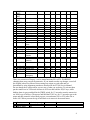
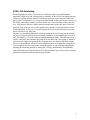
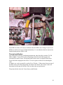
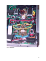
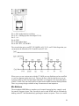
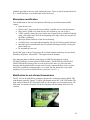
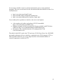
Yaesu FT-100 undocumented
Compiled by PA3GMP. Printed 4 April 2004
TABLE OF CONTENTS
MENU SETTINGS OVERVIEW ............................................................................................. 3
AT-11MP AUTOTUNER ................................................................................................... 7
ATAS-100 AUTOTUNING ................................................................................................ 8
WHAT'S IN THERE? ................................................................................................ 13
HOW DO I TAKE IT APART? .................................................................................. 14
HOW DO I PUT IT TOGETHER?............................................................................ 14
ATAS100 MANUAL TUNING ......................................................................................... 14
ATAS-1/ATAS-2 SETTINGS ......................................................................................... 15
ATBK100 GROUND PLANE KIT .................................................................................... 15
CWID WITH ARTS........................................................................................................ 16
BAND DATA PIGTAIL PINOUT ........................................................................................ 16
CTCSS AND MEMORY FUNCTIONS ................................................................................. 16
DUPLEXERS .................................................................................................................... 17
EXTRA BANDS ............................................................................................................... 17
FACTORY MODIFICATIONS ............................................................................................. 17
Intermittent High SWR ICON ................................................................................... 17
Thermal modification................................................................................................ 20
FC-20 AUTOTUNER ....................................................................................................... 24
FIRMWARE UPGRADES ................................................................................................... 25
KEYPAD FREQUENCY ENTRY ......................................................................................... 25
MANUAL REVISIONS ...................................................................................................... 25
MEMORY PROGRAMMING .............................................................................................. 26
MIC ADAPTER ................................................................................................................ 27
MIC BUTTONS ................................................................................................................ 28
MICROPHONE MODIFICATION ......................................................................................... 29
MODIFICATION FOR OUT-OF-BAND TRANSMISSION ........................................................ 29
OUTPUT POWER (MEASURED IN AND OUT OF BAND) ....................................................... 31
POWER CONNECTORS/LINE FILTERS .............................................................................. 34
PSK31/SSTV/ETC. SOUNDCARD INTERFACE WITH THE FT100...................................... 34
PROBLEMS WITH FT100 RADIOS .................................................................................... 37
REPEATER OFFSETS ....................................................................................................... 37
RF EXPOSURE ................................................................................................................ 37
TRANSMIT PROBLEMS ON 80/160M................................................................................ 38
S-METER ANOMALIES ................................................................................................... 38
SATELLITE OPERATIONS ................................................................................................ 40
SEPARATION KIT (YSK100)........................................................................................... 41
SERIAL NUMBERS .......................................................................................................... 41
SIDETONE/BEEP VOLUME ADJUSTMENT ........................................................................ 41
SQUELCH SETTINGS FOR FM AND SSB .......................................................................... 42
STORING MEMORIES REMOTELY ..................................................................................... 42
1
SWR METER INTERPRETATION ...................................................................................... 42
UP/DOWN BAND SWITCHING ....................................................................................... 43
V/U MESFET PRE-AMP ADJUSTMENT ........................................................................... 43
YAESU CONTACTS ......................................................................................................... 44
2
Menu settings overview
Nr. Function
Default
1
2
3
4
5
Dial Pulse
Beep
Scan Mode
Scan Speed
Resume
tuning rate
key and buttons
scan restart
dwell time
hold time
6
DW-time
polling interval
7
8
104 codes
normal or invert
9
10
11
12
13
14
15
16
DCS Code
DCS
ENC/DEC
ARTS Beep
CW ID
ID
Tone freq
Dimmer set
Peak Hold
Scope moni
DSP mic eq
17
18
19
20
21
22
23
24
25
26
27
28
29
30
31
DSP NR
DSP LPF
DSP HPF
BPF Width
HF TX PO
50M TX PO
144M TX PO
430M TX PO
Mic Gain
FM Mic Gain
Comp Level
AFSK Level
APO Time
TOT Time
CW-W Filt
Opt. 4 Opt.
5
1
10
23
tn-rn
754
tn-rr
ALL
oFF
ALL
on
rAng
oFF
88.5
oFF
oFF
oFF
oFF
67
oFF
on
Cont
oFF
7
6000
100
240
100%
100%
100%
100%
50%
50%
50%
50%
oFF
20
oFF
1
1000
100
60
0
0
0
0
0
0
0
0
oFF
oFF
oFF
254
63
oFF
Chec
1 hi
cut
16
6000
1000
120
100
100
100
100
100
100
100
100
1
1
on
oFF
oFF
300
6_0
HF 2.5
KHz
PCt-F
HF 2.5 2.5
5_0
rtty-L
rtty-U
PCt-L PCt-U
170
nor
1200
-3000
425
Car
9600
3000
850
offset
170
nor
1200bps
2125
set for TNC
2125
1170
1700
2125
beep mode
enable/disable
up to 8 char.
39 tones
63 dimmest
.5 sec hold
sweep mode
equalization
reduction level
high cut
low cut
DSP CW filter
power
power
power
power
SSB-AM modes
FM mode
SSB-AM modes
input sensitivity
hours to shutoff
minutes
optional wide
path
32 AM/CW-N Filt AM or CW-N
filter
33 FM Dev
deviation
34 AFSK mode
mode-sideband
35
36
37
38
frequency shift
offset
RTTY Shift
RTTY display
Packet rate
Packet
display
39 Packet tone
200
on
tinE
10 ms
5
seconds
5
seconds
23
tn-rn
Opt. 1 Opt. 2 Opt.
3
100
200
on
oFF
StoP
buSy tinE
10
100
1
10
tr-rn
Remarks
tr-rr
oFF
SgL
2 lo
cut
oFF
3 mid
only
240
2
20
3
PCkF
2210
3
40 HF RPT
SHIFT
41 50 RPT
SHIFT
42 144 RPT
SHIFT
43 430 RPT
SHIFT
44 144M ARS
45 430M ARS
46 Keyer Type
47 Dot Size
48 Dash Size
49 CW-Delay
50 CW Pitch
51 CW Break-in
52 Keyer Speed
53 QSK Delay
10m shift
0.1
0
10MHz
6m shift
0.5
0
10MHz
2m shift
0.6
0
10MHz
440 shift
5
0
10MHz
auto shift on-off
auto shift on-off
keyer or paddle
dot to space
dash to space
semi QSK
sidetone offset
QSK
on
on
EL2
10
30
.5 sec
700
FULL
50
5
oFF
oFF
EL1
0
0
0
400
FULL
1
0
on
on
EL2
125
125
2.5
500
Seni
100
30
50
.5 sec
SqL
diAL
on
0
0
SqL
PAnEL
on
100
2.5
rF
diAL
oFF
1
10
1
0
2
16
oFF
AtAS1
-0.2
-0.2
-0.2
-0.2
oFF
AtAS-2 tunEr
shifts output
times
54 VOX gain
input sensitivity
55 Vox delay
hang time
56 SQL/RF gain mode of control
57 Lock mode
lock mode
58 AM&FM Click select knob
function
59 Mic SW set
mic buttons
60 NB Level
IF noise
blanking
61 Tuner/ATAS device selection
62
63
64
65
66
RX LSB CAR
RX USB CAR
TX LSB CAR
TX USB CAR
5167.5 KHz
Carrier point
Carrier point
Carrier point
Carrier point
Alaska
emergency
0
0
0
0
oFF
buG
600
700
800
3
0.5
0.5
0.5
0.5
on
USA only
There is a second set of factory / service menu functions F01 to F59. WARNING:
changing these may reset all the memories. If you intend to make any changes, record all
the original values first. Most of these settings are unique to each radio and are
determined by using alignment procedures described in the FT100 Service Manual.
Do not change these values unless you are sure of what you are doing. To activate them
put the transceiver in VFO mode and turn it off. Press and hold the A,B,C keys; while
holding them in, press and hold in the [PWR] switch for 1/2 second to turn the transceiver
on. Now let go of all keys. Then press and hold the FUNC key for 1/2 second to get to the
menu and then rotate the select knob to get to a second menu (F01 to F59) after #66 or
before #01. When you turn the rig off and back on it returns to the normal menu.
Nr. Function
F01 144 RF GAIN
F02 430 RF GAIN
Default (may vary)
166
166
Set to:
Remarks:
4
F03
F04
F05
F06
F07
F08
F09
F10
F11
F12
F13
F14
F15
F16
F17
F18
F19
F20
F21
F22
F23
F24
F25
F26
F27
F28
F29
F30
F31
F32
F33
F34
F35
F36
F37
F38
F39
F40
F41
F42
F43
F44
F45
F46
F47
F48
F49
F50
F51
F52
F53
F54
HF RX IF G
50 RX IF G
144 RX IF G
430 RX IF G
S FULL SCALE
SSB SQL
FM N SQL
FM RF SQL
HF IC ALC
V/UHFIC ALC
HF PO 10W
HF PO 50W
HF PO 100W
50 PO 10W
50 PO 20W
50 PO 50W
50 PO 100W
70 PO 10W
144 PO 20W
144 PO 50W
430 PO 20W
1.8 TX IF G
3.5 TX IF G
7 TX IF G
10 TX IF G
14 TX IF G
18 TX IF G
21 TX IF G
24 TX IF G
28 TX IF G
50 TX IF G
70 TX IF G
144 TX IF G
430 TX IF G
ALC METER
HF PO METER
50 PO METER
144 PO METER
430 PO METER
HF REV ALC
50 REV ALC
70 REV ALC
144 REV ALC
430 REV ALC
SWR METER
OVER HEAT 1
OVER HEAT 2
CW CAR LEVEL
AM CAR LEVEL
FM TX FREQ
TRX LSB CAR
TRX USB CAR
98
112
108
82
144
33
88
56
23
22
26
83
123
25
45
83
123
063 <<< 70 MHz
65
120
139
76
69
63
63
67
71
72
72
75
104
127
97
93
196
170
172
105
63
34
34
127 <<< 70 MHz
173
60
141
230
235
166
113
-32.47
0.11
-0.01
5
F55 blank
F56 blank
F57 DESTINA HF
F58 DESTINA V/U
USA < JPN,JAIA,
STD,EU,FRAN,BEL,
GER,USA,AUS,UT
USA < JPN,USA,
EU1,EU2,EU3,EU4,
AUS
F59 blank
6
AM Settings
Gary Mitchelson, N3JPU, has done some interesting tests with the AM settings and found
some settings that work much better than the defaults. The parameters that sound the best
are: PO set to 25, Mic gain to 40 to 50 and Carrier Level set to 225 (F51 menu). You can
hear a sample of his testing at: http://mywebpages.comcast.net/n3jpu/
Most owners who have had difficulties with AM audio quality have reported that the 6k
HZ option AM filter (p/n XF117A) is an absolute necessity for both transmitting and
receiving in AM mode.
The following procedure will result in excellent AM transmit operation with the FT100(D). The User's Manual does not include any guidance regarding this. For this
discussion I assume HF AM operation.
•
•
•
•
•
•
Install the 6 kHz filter. You need the filter in order to have proper AM operation.
Turn on the unit while holding in the A, B and C buttons in order to access the
sub-menu "F" functions.
Place the unit in AM mode.
Set the MIC gain setting to 17 (seventeen).
Using the F51 function, key the mic and set your un-modulated carrier output
power to 25 Watts, no higher.
That's it. You should now have 100 Watts PEP on voice peaks which is 6 dB (4
times) the un-modulated carrier power.
Extra hints: Set function F15 to 170 in order to avoid non-linear compression on voice
peaks. But note the original setting and restore F15 to the factory setting when you
operate SSB and CW. You should have 100 Watts output in CW mode when F15 is
properly set.
You can use the speech processor during AM operation but you must not exceed a setting
of 17 when using it, just as with non-processed operation. The PROcessor control is
simply a second MIC gain control which over-rides the MIC gain control setting
whenever you enable the PROcessor. The FT-100(D) actually does not allow you to vary
the compression percentage.
AT-11MP Autotuner
Some owners have opted to purchase the AT-11MP auto tuner from LDG Electronics.
This is available in either a kit or assembled format and does not suffer from the
CAT/FC-20 limitations.
There is an accessory for the FT100/D called the OTT or 'One Touch Tune' available
from W4RT.com that allows you to use the 'Tune' button on the FT100 to control the
tuning function of the AT11 directly from the FT100. It also allows you to maintain the
CAT compatibility which is something you normally lose with the FC-20 autotuner.
7
ATAS-100 Autotuning
The tuning behavior of the ATAS can cause confusion unless you understand the
algorithm it follows to find a good position. Normally, if the ATAS is installed correctly
and it successfully autotunes itself, it will always go in the correct direction when you
press in the TUN button for 1/2 second once it has found its first good match. However, it
the ATAS cannot find a match, it will run all the way to one end, turn around, and start
over. This process can take a while since the antenna runs 'open loop' when it loses its
position. Since it doesn't know which position the antenna is in unless it makes its own
successful match, it needs to be sure it has gone all the way to the end before reversing,
which can take a very long time.
Anytime it is not sitting right where it found a match all by itself, it can end up starting
out in the wrong direction next time. Examples would be if you manually do even just a
little fine tuning, or if you interrupt autotuning and change bands. Then the rule is very
simple: it starts the next autotune by going in the last direction it was going in, which is
not necessarily right. If it's going in the wrong direction, the antenna will move all the
way to a stop and then it will have to turn around and start over again after a long delay.
If you recognize that it's going in the wrong direction, you can avoid the long delay by
aborting the autotuning process by hitting the TUN key momentarily, then manually
move the antenna just a little (with the PTT and up or down keys) in the correct direction,
and then recommence with the autotuning procedure.
8
ATAS-100 Disassembly
9
10
11
12
Disclaimer:
The following procedures can possibly void your warranty.
WHAT'S IN THERE?
(And a little on how it works)
The stainless steel whip is mounted on top of a loading coil (under the rubber boot). The
coil consists of copper wire wound around a "grooved" fiberglass rod. Part of the reason
the antenna is guaranteed to work on 40,20,15 and 10m HF bands but not on 12,17 and
30m is that the spacing on the coil is wider at the resonant points on the coil on the
"primary" bands allowing easier tuning.
The loading coil slips into the "body" of the antenna where spring loaded contacts make
the necessary connections. At the base of the coil and rod is a Teflon disk that makes
sliding contact with the inside of the tube and is threaded for the brass "screw" rod that
raises and lowers the coil.
About 7" below the contacts is the motor and clutch assembly (at the middle rubber
cover). Two wires run from the motor to the controller board that is mounted on top of
the base unit.
The base (matching unit) consists of a chromed top cap which includes the mount for the
motor controller board. Below this is a 3" black plastic tube that forms an insulator. At
the bottom is the threaded chromed base cap that is where the SO-239 connector screws
13
in. This base assembly is secured with pins and would be hard to dissemble without
damaging.
Inside this is an RF choke coil (I'm not sure if it is air wound or on a torrid) that makes
this whole antenna DC grounded. This protects the radio from damage from whip contact
with power sources, static build up, etc. The coil also helps with matching the antenna
and contributes to the high Q of the design.
Connected to this is a capacitor that leads to the center pin on the SO-239 receptacle in
the base. This capacitor is also part of the "broad band" matching network.
HOW DO I TAKE IT APART?
1.
2.
3.
4.
5.
6.
Extend the antenna fully (40m).
Remove from vehicle and take it to a clean work surface.
Remove the whip for ease of handling.
Slide up the 2 rubber covers exposing the screws.
Remove the 3 lower screws above the base.
CAREFULLY remove the base by gently pulling down while using a slight
rocking motion (the resistance is from a O ring).
7. Carefully withdraw the base assembly while noting the routing of the motor wires.
8. Unplug the micro connector from the motor controller board (the red and black
wires that leads to the motor-clutch assembly), and set the base aside.
9. Mark on the shaft the location of the bottom of the boot, then slide the boot
upwards exposing the loading coil.
10. Remove the remaining 6 screws on the antenna.
11. Carefully slide up the loading coil which also removes the motor-clutch assembly
(be careful with the alignment pin).
There is more than can be disassembled, but the above steps are all that is needed for
most maintenance and repairs. While you're in there, clean the moving surfaces up and oil
with a light oil (like mineral oil) that won't harm plastics while taking care not to
contaminate the contacts, coils and connections.
HOW DO I PUT IT TOGETHER?
1. Basically reverse the above procedure.
2. Be careful to make sure the alignment pin (about 7" long) from the loading coil to
the motor-clutch assembly is in place.
3. Pay special attention to the routing of the motor wires to prevent pinching
between the motor controller board and motor-clutch assembly.
ATAS100 Manual Tuning
The ATAS100 can be tuned up and down manually by holding in on the PTT switch and
using the UP/DOWN keys on the front of the radio. If you thought it meant the
UP/DOWN keys on top of the hand mic, you're not alone, as several others have made
the same mistake and the manual does not specify which UP/DOWN keys to use. It has
been noted that the P1/P2 keys on the mic will cause the antenna tune icon to come on if
you push them while holding the PTT, but they do not actually move the antenna.
14
ATAS-1/ATAS-2 Settings
Menu item 61 is has several settings for controlling the way the ATAS100 antenna
works. In the user manual, there are several errors describing this function. On page 14,
the instructions are correct and the easiest way to remember the correct settings are:
ATAS-1 = one antenna ; ATAS-2 = two separate antennas. In other words, if you're using
the ATAS100 on all bands (with a duplexer), choose ATAS-1. If you are using the
ATAS100 for HF only and a separate antenna for VHF/UHF, use ATAS-2. Page 62 in the
manual is backwards from this as is page 94 which recommends that a duplexer is
required with ATAS-2. The newer manuals may have corrected these errors but as of
manual revision E08981003 the mistakes were still present.
Another user noticed that when either of these selections are made, the radio will not
transmit on the 80 or 160 meter bands so don't forget to switch menu item 61 to OFF (or
to Tuner) when you switch from the ATAS100 to another antenna.
ATBK100 Ground Plane Kit
The ATBK100 is a kit consisting of 3 ground radials for the ATAS100 intended to make
it suitable for use as a base antenna. Although there is no information available on the
Yaesu website about the ATBK100, this US$90 kit is supposed to supply a ground plane
for the 50 MHz, 144 MHz, and 430 MHz bands. One owner responded that he was able
to get the antenna to work on other HF bands by adding two 20' lengths of wire to the
ATBK100 to act as a counterpoise.
Audio Settings (improving transmitted audio performance)
Bill, N4XEO, has contributed the following advice for those who are not satisfied with
their audio reports. First, make sure the rig's chassis is grounded to the frame of the
vehicle and that the rig is powered directly off the battery with minimal voltage loss
through the power cable. Secondly, make sure that the voltage is sufficient for the rig.
The specifications call for 13.8V DC and so if you're not running the engine, it's likely
that your voltage won't run the rig correctly for very long. This will be apparent when
operating with the engine off as the battery voltage begins to sag down around 12V.
Here are some of the settings Bill recommends that have worked for him and others to
improve the audio:
Menu Item
Description
Value
25
Mic Gain (for SSB and AM 40
modes)
26
FM Mic Gain
45
27
Compression Level
40
33
FM Deviation
5
62
RX LSB Carrier
+050
63
RC USB Carrier
+050
64
TX LSB Carrier
-200
65
TX USB Carrier
-200
15
CWID with ARTS
The CWID feature appears to have a bug. It sends out the 'W' as a 'U' in Morse code. The
CWID feature, when enabled, transmits a CW identifier every 10 minutes when the radio
is operating in ARTS mode. Here is a set of instructions on how to test if your radio is
affected:
Go to menu item 11 and enter a CW ID string with some W's in it. To do this, press
Select knob and use the main dial to select the characters. Press the Select knob to
advance one character. Program all 8 characters using the Select button to advance. When
you get them all programmed, press Select again and the radio will playback the ID
you've stored. Use a tape recorder unless you think you can copy comfortably at 35-40
wpm. If you want to hear it on the air, proceed with the following instructions.
Go to menu item 10 and enable the CW id during ARTS operation.
Set the radio to a clear simplex FM frequency.
Press the FUNC key until you get to screen 3 which shows TON DCS and ART. Enable
ART.
Listen on another radio. The DCS code will be sent every 15 seconds and the CW ID will
occur every 10 minutes. Again, use a tape recorder, as the ID comes across at about 35-40
wpm. I have a little recorder that will allow me to record at 2.4 cm/sec and play back at
1.2 cm/sec so I can listen to the CW at a more comfortable 18-20 wpm.
Band Data Pigtail Pinout
The Band Data pigtail can control a VL-1000 amplifier when set internally to control an
amplifier. The normal mode is for the CAT/Tuner function, but it can be rearranged with
an internal jumper (shown on page 19 of the manual) to control an amplifier. If you're
curious about how the signals work in that mode, the table below shows the logic
depending on the band selected. The images to help explain this better are shown here.
Yaesu FT-100D Band Data Output map H=4.4 vdc L=0 vdc
Band 1.8
3.5
7
10
14
18
21
24
A
H
L
H
L
H
L
H
L
B
L
H
H
L
L
H
H
L
C
L
L
L
H
H
H
H
L
D
L
L
L
L
L
L
L
H
28
H
L
L
H
50
L
H
L
H
144
H
H
L
H
440
L
L
H
H
CTCSS and memory functions
Storing CTCSS frequencies in memory along with frequencies is a bit tricky. When
putting frequencies into memory from the VFO you must have encode on and the display
16
must show ENC for the CTCSS tone to go into memory. If the main display does not
show ENC when the frequency is put into memory, the CTCSS setting is not stored.
Duplexers
The ATAS100 is designed to tune on all the bands on which the radio transmits including
2m and 70cm. This requires a duplexer like the Diamond MX62M or the Comet CF706
to connect the VHF/UHF and HF pigtails together. (The actual cross-over
frequency between the pigtails is 70.5Mhz.) However, many people prefer to use a
separate antenna for the VHF/UHF bands since those antennas typically cost about the
same price as a duplexer and usually have some gain whereas the ATAS100 has no gain
on VHF/UHF. Also, with separate antennas you don't have to worry about retuning when
switching between VHF/UHF and HF.
A consideration when using a duplexer is that the DC voltage for tuning the ATAS-100 is
supplied through the HF pigtail. Therefore, this pigtail must always be connected to the
ATAS for tuning purposes. Also, it must not be capacitively coupled inside the duplexer
or it will block the DC motor control voltage.
Extra Bands
You may have noticed two extra bands appear while moving through the normal ham
bands using the up/down keys. Apparently, the rig remembers an extra band for HF and
another for V/U portions of the radio. If you tune outside a normal ham HF band either
accidentally or intentionally, you'll notice that this band will now appear in a list of bands
as you use the up/down keys. The same is true for the V/U side of the radio. For example,
if you tune to the weather band at 162 Mhz, it will appear in the list between the 2M and
70cm bands. Short of resetting the radio, there's no way to get rid of these bands. Some
have elected to move them to the end of the list by tuning a frequency below 160M or
above 70cm so that they don't appear inside the list of bands.
Factory Modifications
There are two common modifications retrofitted to the FT100s manufactured prior to
2001. These include the fixes for the Intermittent High SWR ICON problem and the
VHF/UHF thermal sensor modification to enable the fans in the V/U receive mode.
Although there had been reports that new radios included the SWR mod, the mod has
been through several iterations and it's possible that even radios purchased today do not
include the 'final' mod with the screws, but rather just the copper tape held on with
adhesive.
Intermittent High SWR ICON
Some owners have had trouble with the HIGH SWR Icon appearing while attempting to
transmit on certain bands. The most common advice is to make sure that the antenna
mount and radio are properly grounded via some heavy braided material to the vehicle
chassis. Some owners have had success in using clamp-on ferrites with the separation kit
17
cable wrapped several times around the ferrite to block common mode current from
getting back into the rig. Ten meters seems particularly prone to the problem. Changing
the feedline length has also helped in some cases, but this seems to move the problem
around more than solving it at the root cause. Also, some owners have found that fixing
the grounding of the LPF board by adding solder around the screw holes and in some
cases tightening the screws or adding star washers was sufficient to make their grounding
problems go away.
However, there is a very effective modification that has worked in every case. The mod
involves fixing the grounding in the coax sockets on LPF of the radio and a metal shield
on the Main Unit. A degradation in the LPF grounding can cause the rig to break into
oscillation (even at lower power) causing the HIGH SWR icon to appear intermittently
even with a good antenna match on the higher HF bands. The mod will eliminate this
oscillation and the high SWR reports. Here are a few pictures of the factory installed
mod. The adhesive copper tape has been replaced screws or clamps that are attached to
the casting web. Note that on the upper strap, they have added a screw and the lower strap
was added and soldered to the shield as well as the coax and also screwed to the casting.
Before the factory mod
18
After the factory mod
19
After the factory mod.
The SWR icon with an 'X' next to it indicates that the SWR is out of range. If you see an
SWR icon with an 'O' next to it flash momentarily, it is an indication that the antenna has
finished tuning and the SWR is 'OK'.
Thermal modification
The cooling fans will only work during transmission when the radio is tuned to 70.500
MHz or higher. Yaesu will fix this by mounting a thermal switch that bypasses the
electronic fan control circuit. The thermal mod is done on an 'as requested' basis since
Yaesu feels that keeping the fans off in V/U receive poses no threat of overheating the
radio.
A simpler way to do it yourself is to add a 50 to 120 ohm / 1 Watt resistor between one of
the black wires of the fans and ground, for instance the chassis. The resistor value will
determine the idle speed of the fans. Pick one that suits your preferences.
The pictures below show the Yaesu factory modification:
20
Prior to modification
21
Prior to modification
22
After modification
23
After modification
There is also a software work-around to get the fans running on 2 and 70 on RX only,
by using the 'SPL" button and VFO A/B to turn on the SPLIT function.:
•
•
•
Set the VFO "A" on the RX QRG on 2m or 70cm band and VFO "B" on a TX
frequency on HF or 6m.
Briefly press the TX PTT (which briefly transmits on HF or 6m)
Now the fans are running full speed and will slow down in a few seconds without
stopping entirely.
FC-20 Autotuner
The FC-20 auto tuner is available as an accessory for the FT-100. The FC-20 was
designed specifically for the FT-847 and FT-100 and is intimately mated to them. The
FC-20 is capable of matching a SWR up to 3 to 1. It features 100 memories that
memorize your favorite frequencies so that when you return to them, the unit can
"instantly" tune to a frequency without having to evaluate the SWR as it tunes.
People have identified two limitations to the FC-20: the matching range and the inability
to use both CAT control and the tuner simultaneously. If you don't need a wide matching
24
range and don't use the CAT control with the radio, then the FC-20 is reported to operate
very smoothly and is well integrated with the radio. If these limitations are important to
you should consider the LDG AT-11 autotuner.
Firmware Upgrades
A common question asked regarding the FT100 is whether or not its firmware can be
upgraded to add some missing feature in the future such as memory management via a
PC or keypad frequency entry. Unfortunately, the design of the FT100 does not allow for
this kind of feature since the microcontrollers are not flash-based, but rather OTP (onetime programmable) devices or even mask-based in later production runs. They can be
removed and replaced, but this takes special SMT (surface mount technology) soldering
equipment.
There are three microcontrollers in the FT100:
•
•
•
The FT100's main processor, mounted on the controller unit, is a 32MHz, 80-pin,
16-bit CPU from NEC (P/N UPD78P4038).
There is also an 8 MHz, 48-pin, 8-bit microprocessor on the controller unit made
by Fujitsu (P/N MB89P133PFM) that appears to be the one that does the
electronic CW keying since it only has a few inputs and they connect to the 'key1
and key2' on the back of the unit. It uses a few of its serial pins to communicate
with the main CPU. FMI see: the Fujitsu MB89P133PFM datasheet.
The display board has a 5 Mhz, 80-pin, 8-bit NEC microprocessor (P/N
UPD78P054) and that communicates with the main CPU via a serial link.
Keypad Frequency Entry
There is no way to key frequencies into the FT100 via the microphone's numeric keypad
(standard on US models). That numeric keypad is only used for touch tone encoding
when the PTT is held. However, John Hansen, W2FS, has designed an auxiliary keypad
called the Millenium QSYer that can be used to enter frequencies from an external
keypad. The cost is US$70 for the kit or US$95 for the assembled and tested unit. It can
also be used with the Yaesu FT817 and Icom IC706 mobile radios.
For details and ordering see http://www.john.hansen.net/keypad.htm
Manual Revisions
The manual revision can be determined by the part number of the manual. This number is
located directly below the barcode on the back cover of the manual and will have a
format like 'E08981003'. The number on the lower left-hand corner of the back cover
with the format such as 9907V-EY is the printing lot number and does not contain
information relevant to the revision of the manual.
Another common question asked is where one can get a copy of the owner's manual,
preferably on line. You can find it on http://k0lee.com/images/FT-100D%20Manual.pdf.
25
There is also an FCC site that has manual, schematic, and other information related to the
submission for approval by the FCC. Unfortunately, this information is quite out of date
since a product is normally submitted to the FCC well in advance of its actual availability
and the manual is often just a rough draft of the finished manual. An exploded view of
the rig can be found on http://k0lee.com/images/FT100%20Exploded%20View.pdf.
There is also an effort underway to make the alignment procedures available on
http://k0lee.com/techsupp.htm.
The FCC site can be found at: http://www.fcc.gov/oet/fccid/. To get the information, use
the Grantee code K66, and the equipment product code FT-100, and select View
Exhibits. Here you may view schematics, photos, block diagram, parts lists and a PDF
version of the user manual. The manual shown appears to be only a rough draft with 36
pages of information vs. 108 in the finished manual. It contains no illustrations. The
manual and schematics were scanned and converted to .pdf and you will find resolution
of the schematics is not high enough to be usable. It is highly recommended that if you
lost your manual or bought a used radio without one, that you contact Yaesu Parts and
purchase a new one.
Memory Programming
There are a few common difficulties in programming the memories. The radio has a
mode to allow rapid tuning through the memories by skipping unused memory locations.
This feature must be disabled to store frequencies in an unused memory location. To
disable it, place the rig in memory mode by pressing the VFO/M button until MEM is
shown in the display. Then hit the STEP key to enable or disable the vacant memories
selection. Reverse the procedure with the same sequence. Turning the SELECT knob will
help you to determine if the radio is in rapid mode if you see it is jumping over unused
memory locations.
Another difficulty is getting the memories stuck in a particular memory group. The main
memory [1-300] is divided up into 6 separate 50-memory groups. You can restrict tuning
to a single group by pressing in on the SELECT dial for 1/2 seconds while in MEM
mode. You reverse the procedure with the same sequence. You will see an GCH appear
in the lower left hand corner of the display if you are locked into a particular memory
group 1 through 6. Pressing the SELECT for 1/2 seconds will put it back in memory
channel mode and it will display MCH in the lower left hand corner. If you are not
careful and only press the SELECT momentarily, it will put you in VFO mode and you'll
have to press the VFO/M key to get back into memory mode. This is not explained
correctly on page 71 of the manual.
There are no provisions for alpha numeric labeling of the memories in the FT100.
26
Mic adapter
PowerWerx (www.powerwerx.com) sell an adapter to connect standard base
microphones to the FT100. For the
lordly sum of $30,-- you are the proud
owner of a short piece of wire with a
cheap connector on both ends.
It might be cheaper to do it yourself. (In
fact it is... much cheaper.) Here's what
you need to know: The up/down/PTT
switches are all connected to the SW1
line on the FT100 microphone jack.
Different resistor values address
different buttons:
The pin-out on the FT-100 / 90 / 8100 Mic jack is as follows:
27
Pin 1: SW 2 multi-function switching
Pin 2: N.C. (9600bps packet data output FT-90)
Pin 3: + 9 v
Pin 4: GND
Pin 5: Microphone Input
Pin 6: SW 1 PTT, UP, DOWN
The circuit below gives you PTT, UP, DOWN, ACC, P, P1, and P. Don't forget that you
can program the functions of P, P1 and P2 on the FT-100:
When you try to use various mics with the FT-100D you may find that you have muffled
or very low apparent audio drive level. This may be due to the fact that the mic you are
trying to use has a relatively high output impedance as compared to the input impedance
of the FT-100D. This can result in the low audio and/or muffled transmit audio problems.
There is a pre-amp design available at http://hometown.aol.com/ampmicro.
Mic Buttons
The microphone MH36B has a complete set of numeric buttons but they cannot be used
for numeric frequency input. They can only be used to send DTMF tones in FM mode by
holding in the PTT and simultaneously pressing the numeric sequence. There is no audio
28
feedback provided to the user while sending the tones. There are also 4 buttons labeled A,
B, C, and D but there is no documented use for these keys.
Microphone modification
This modification to the stock microphone will bring you excellent transmit audio
reports:
• Open the mic case.
• Remove the 3 larger internal screws and the 1 smaller screw in the microswitch.
• Move the PC board away from the tiny mic element so you can access it.
• VERY carefully remove the tiny electret mic element from its cylindrical housing
using a fine tipped tool. Work it out beginning at the edge where you can pull on
the rubber "grommet".
• Shake the plastic baffle out of the electret housing.
• Carefully force a sewing needle through the 3rd mic hole that's normally blocked.
• Insert the electret element back into its cylindrical housing carefully, leaving the
plastic baffle out.
• Re-assemble the mic case.
Set the MIC gain to about 55 and enjoy the excellent transmit audio that was previously
limited by the plastic "noise baffle". The improvement is dramatic.
Note that most hams in Europe seem to have an MH-42b microphone on their
FT100/FT100D (the version without DTMF buttons). The MH-42b mic DOES NOT
NEED THIS MOD. Instead of the two-out-of-three holes there is a slit in the mike
housing, and the plastic baffle is made out of loosely compressed fibers in this version,
which does not block sound noticeably. As a result, this mic doesn't have any audio
problems. So if you have an MH-42b mic, just leave it as it is. :-)
Modification for out-of-band transmission
The FT-100 can be modified to transmit on frequencies outside the amateur bands. This
modification opens the Yaesu FT-100 for full transmit on the HF, VHF, UHF bands. The
mod works for both the FT100 and FT100D. It will not allow you to transmit on the 220
Mhz band. All memory channels will be lost. Repeater offsets remain intact for USA
versions.
Back of front panel. Top left corner.
29
•
•
•
•
•
•
•
•
•
•
•
•
•
Remove jumpers 1 & 2, leave 3 & 4.
Remove Front Panel from radio and open the rear cover from the Front Panel unit.
Be careful, a cable connects them together. Locate and remove R6035 (1) and
R6036 (2) on the display board. Note: The factory removed R6035 on my radio so
I only had to remove R6036. You should end up like the picture above.
Reassemble and install the Front Panel on the radio.
Note: if the 2 SMD diodes not are present, then you should skip the above steps.
Press [DPS] and [LOCK] keys, while holding them in, press and hold the [PWR]
switch for 1/2 second to turn the transceiver on. Wait for the transceiver to
initialize itself. You WILL LOOSE all memory channels programmed. Turn the
transceiver off.
Press and hold [DWN] and [STEP] keys; while holding them in, press and hold in
the [PWR] switch for 1/2 second to turn the transceiver On. Now let go of all
keys. The display will read "r on" for a 1/2 second or less (it may be so quick that
you don't see it but continue with the mod).
Set the dial frequency to 375.72727MHz. You will need to use LSB, USB, or CW
to get the last digits. After you enter 375.72727Mhz, press the MODE button to
go back to FM Mode, and turn the power off
Press and hold [DWN] and [STEP] keys; while holding them in, press and hold in
the [PWR] switch for 1/2 second to turn the transceiver On. Now let go of all
keys. The display will read "HF on" for a 1/2 second or less (it may be so quick
that you don't see it but continue with the mod).
Set the dial frequency to 549.61163MHz You will need to use LSB, USB, or CW
to get the last digits.
After you enter 549.61163Mhz, press the MODE button to go back to FM Mode,
and turn the power off.
Press and hold [DWN] and [STEP] keys; while holding them in, press and hold in
the [PWR] switch for 1/2 second to turn the transceiver On. Now let go of all
keys. The display will read "vU on" for a 1/2 second or less (it may be so quick
that you don't see it but continue with the mod).
The modification is complete. Turn the radio off and back on to continue.
RX & TX: 1.8MHz-30MHz, 50MHz-54MHz, 140MHz-174MHz, 420MHz470MHz.
The following Yaesu document also explains an out-of-band modification:
30
Output power (measured in and out of band)
Frequency
MHz
432
145
50
28
100%
dBm
43.3
47.1
49.7
50.0
W
21.4
51.3
93.3
100.0
50%
dBm
39.3
43.2
45.1
45.3
W
8.5
20.9
32.4
33.9
10%
dBm
33.5
37.4
42.5
38.1
W
2.2
5.5
17.8
6.5
0%
dBm
30.8
35.2
35.0
35.0
W
1.2
3.3
3.2
3.2
31
24.9
50.0 100.0 45.3 33.9 38.1 6.5
21
50.0 100.0 45.4 34.7 38.1 6.5
18.15
50.0 100.0 45.3 33.9 38.1 6.5
14
50.0 100.0 45.3 33.9 38.1 6.5
10.1
49.9 97.7 45.2 33.1 38.0 6.3
7
49.8 95.5 45.2 33.1 38.0 6.3
Measured with HP432 + Narda 40dB attenuator
** Power sensor range from 10MHz to 12Ghz
3.2
3.2
3.2
3.2
3.2
3.1 **
HF
Watts
All readings at 100% power on all bands:
Frequency Output
(MHz)
(Watts)
2
82
3
83
4
82
100
5
83
6
83
80
7
88
8
80
9
85
60
10
84
11
88
40
12
86
13
81
14
80
20
15
82
16
84
0
17
68
18
85
19
85
20
82
21
85
22
83
23
85
24
85
25
85
26
85
27
81
28
81
29
71
30
62
35.0
35.0
35.0
35.1
35.0
34.9
Watts
32
34
35
32
28
Watts
29
26
23
20
17
14
11
8
40
20
Watts
0
50
Frequency
5
2
Frequency
50 Mhz
Watts
Frequency
50
51
52
53
54
HF
51
52
53
54
Frequency
32
50
40
30
VHF
20
10
168
165
162
158
155
152
149
146
143
0
140
Frequency
UHF
25
20
15
UHF
10
5
470
465
460
455
450
445
440
435
430
0
425
Watts
5
7
11
16
21
23
23
23
23
23
23
23
23
23
23
23
23
23
22
22
22
22
60
420
Frequency
420
421
422
423
424
425
426
427
428
429
430
431
432
433
434
435
436
437
438
439
440
441
VHF
Watts
40
44
48
48
48
48
48
48
48
48
48
48
47
45
44
32
26
22
17
14
10
8
7
5
5
4
2
1
1
0.5
Watts
140
141
142
143
144
145
146
147
148
149
150
151
152
153
154
155
156
157
158
159
160
162
163
164
165
166
167
168
169
170
Frequency
33
442
443
444
445
446
447
448
449
450
451
452
453
454
455
456
457
458
459
460
461
462
463
464
465
466
467
468
469
470
22
22
22
22
22
22
22
22
22
22
22
22
22
20
14
9
6
4
2
1
1
1
1
1
1
1
1
1
1
Power Connectors/Line Filters
An excellent source for power connectors can be found at www.powerwerx.com. They
carry the OEM connectors and shells for the FT100 (and other rigs) as well as the
Anderson Powerpole connectors which allows you to make up cables so that it's easier to
interchange different brands of radios with various power supplies. They also carry line
filters to reduce alternator whine from the DC power source.
PSK31/SSTV/etc. soundcard interface with the FT100
Operating soundcard programs like PSK31 is accomplished by using the DATA Jack on
the rear panel of the radio. The definitions of the jack as provided on pages 20 and 21 of
the manual are:
Pin 1: Data In (AFSK input for soundcard)
Pin 2: GND
Pin 3: PTT
Pin 4: 9600 Baud out
Pin 5: 1200 Baud out (audio out for soundcard)
Pin 6: Squelch
34
It is necessary to build a circuit or purchase and interface prior to using soundcard
programs. There are several sources on the web that describe these interface circuits. You
can find them at:
•
•
•
http://www.qsl.net/wm2u/psk31.html
http://krasnodar.online.ru/hamradio/soundint.htm
http://www.qsl.net/kb8wow/Psk_Interface_Page1.html
If you would prefer to purchase an interface, there are several options:
•
•
•
A kit complete with cables and enclosure $25 ($39 assembled)
http://www.packetradio.com/PSK31.htm
Rigblaster complete kit fully assembled $90 (but not available with FT100 data
connector) http://www.westmountainradio.com/RIGblaster.htm
Buscommco fully assembled interface $50 configured for FT100
www.buxcommco.com
The cable for the DATA jack is the CT39 and costs U.S.$10 from Yaesu. Jon, WA2NKF,
put together a diagram on how to interface a soundcard to the FT100 using the CT39 or
other 6-pin DIN connector. It is a very simple interface with a minimal number of
external components to enable the PTT:
35
36
Sandor, KG4FET, has had good success using the FT100 for PSK31 and recommends
using the USB mode (not RTTY mode). Playing around with RTTY or AFSK mode
settings on the FT100 will only cause confusion. Sandor also used 1:1 600-ohm isolation
transformers on the TX and RX lines as well as an opto-isolator for the PTT.
Problems with FT100 radios
Several owners of the early FT100 radios experienced failures of the V/U output
transistor. The word from Yaesu was that solder flux left on the board was to blame.
Another common issue is related to the Intermittent High SWR ICON problem discussed
elsewhere in this document. Overheating on V/U receive was also an issue on units
manufactured prior to 2001 and can be fixed with a thermal sensor modification that
Yaesu has applied as a retrofit. The ATAS100 antennas seemed to have a rash of early
failures where they refused to move after a while. This appears to have been corrected
with a new H bridge that drives the motor.
Repeater Offsets
The repeater offsets are determined by the values set in menu items 40-43. If you need to
program a memory that has a non-standard offset, use the DUP memories since the
repeater offset is not stored with the other parameters in the standard memory locations
(1-300).
Frank, PA4FR, adds this information as an alternative to using DUP memories: FT-100
ARS (automatic repeater shift) might be activated for 2m and 70 CM bands separately.
ARS is default enabled for both bands. When ARS is enabled, any (!!) manual change to
repeater offset or repeater on/off setting is overridden when you change the channel. The
is actually logical, since ARS defines a certain repeater offset and a certain set of repeater
channels (band-plan). Any changes that violate these ARS settings are "reset" when
changing channel. This is especially confusing in Europe, where the 70CM repeater
band-plan differs per country and therefore the "pre-programmed" repeater band-plan
often is not correct.
The solution: knowing this "strategy" behind ARS operation makes figuring out a
solution very simple: just disable ARS (most likely on 70CM only). Then set one of the
VFOs into the 70CM repeater band and enable repeater shift. YES: repeater shift setting
will be stored with 70CM VFO setting and will remain active when changing channels.
Such a channel can be stored into memory and repeater shift and offset will be stored
with it. (Note that the repeater-shift on/off setting is tied to the VFO and band, just as it is
with other settings like APO)
So, it's not a firmware bug, it's a feature - it's meant to be like this.
RF Exposure
Because the antenna is so close to the occupants of the vehicle with a mobile rig, some
owners have expressed concern about whether or not the installation of the ATAS100
would comply with the FCC's guidelines on RF exposure. I had my ATAS mounted on
37
the corner of the hood which puts it about as close as possible to the driver. Here are the
results of my RF field strength measurements using a Haladay HI3004 RF field strength
meter when running a 100W FM signal as measured in the front seat near the driver's
head:
Band
10M
12M
15M
17M
20M
40M
Field strength
8 V/m
20 V/m
15 V/m
15 V/m
12 V/m
16 V/m
Outside the vehicle, the field strength was about 30V/m when measured 2M horizontally
from the antenna.
The FM signal was about twice the strength of a typical SSB signal since it puts out
100W at 100% duty cycle whereas SSB was about half of that. So the readings above are
about 2 times higher than you would expect in normal HF operation.
The maximum exposure limit for a controlled environment is 61.4 V/m at 30-300Mhz
and it rises as the frequency decreases according to the equation 1842/f. For an
uncontrolled exposure, the 30-300Mhz limit is 27.5 V/m and increases according to the
equation 824/f as the frequency decreases where f is frequency in MHz
You can see from the readings that the fields inside the vehicle are well below the
maximum allowable for a controlled environment such as a ham station, and even meet
the more stringent limits for an uncontrolled environment. Combine that with the fact that
the measurements were taken at 100W with 100% duty cycle, and you can see that this
antenna arrangement is considered to be safe by FCC standards.
Transmit problems on 80/160M
Some FT100 owners find that they cannot transmit on any bands below 40M. This is
almost always a result of having menu item 61 set to either ATAS-1 or ATAS-2. Since
the ATAS autotuning antenna only works with bands 40M and above, the FT100 will
refuse to transmit on 80 or 160M if you set it incorrectly. To get around this, you need to
set that menu item to Tuner or 'OFF' if you're not using an ATAS antenna.
S-Meter Anomalies
Several owners have noticed that the S-meter on the FT100 tends to be somewhat stingy,
particularly with FM repeaters. Many radios will give 60+dB readings on local FM
repeaters whereas the FT100 will rarely register more than an S-9. Some responses to the
FT100 mailing list indicated that the FT100 was correctly reporting signal strength
whereas all the rigs that give readings such as 60+dB were overloading and going into
limiting. If you would like to make the S-meter more sensitive, here are the procedures:
•
First off, tune the radio to receive a strong signal from a local 2M FM repeater.
38
•
•
•
•
Next, to get into the alignment mode, turn the radio off, now press the [A], [B],
and [C] keys, and hold them in while you turn the radio on. Now press and hold
the [FUNC] key, as you normally would to get into the Menu. You'll find that the
Menu is now different.
Rotate the selector knob until you find "F-07 [S FULL SCALE]" on the display.
Make a note of the current setting of this item, so you can go back to it if you
want to. Now adjust this item just like any other Menu item, by rotating the main
dial, until you get a full scale reading on the S-meter.
There also is an adjustment of the 144 MHz RF Gain (F-01) and the 144 MHz IF
Gain (F-05). Perhaps a little adjustment to the RF Gain would help with the weak
repeaters. Whatever you do, make a note of the original settings of these items.
Adding too much front end gain can degrade the intermodulation performance of
the receiver section. Also, if you change the RF or IF Gain, the S-meter indication
will change, too.
Press the [FUNC] key to exit the alignment mode.
If you have the equipment for it, you can more accurately adjust the s-meter by injecting
a 14.200 MHz signal in USB mode into the antenna at +95dbmicroVolt and adjust F07 to
read S9+60dB. You could also adjust it for an S9 reading on 40 Meters using 50
microvolts rms for S9, then "re-calibrate" the S meter mentally by remembering that
above S5 the "S reading" is one S unit higher than actual, and also that S9+20dB is
actually S9+15dB, S9+40 is S9+25 and S9+60 is S9+35.
There is only a single adjustment for the S meter which amounts to a DC offset. (It's NOT
a scalar!) All you can do is shove the entire curve one way or the other. Most simple RSL
indication circuits at least use a DC offset along with a DC gain setting. The latter allows
you to set the steepness of the indicated RSL (receive signal level) function. The whole
business is about proper interpretation of either a detector output or the AGC voltage. The
FT-100D uses the AGC voltage to generate the indicated RSL. But they only included
one control (DC offset) to you're really limited in terms of setting the accuracy of it.
Probably the best thing to do is to calibrate it on your favorite band for the standard
50 microvolts RMS (single sinusoid) for S9 and perhaps characterize your "indicated
RSL versus actual RSL" so at least you know how to translate what the meter is
indicating.
FT100D CW signal. Assume first segment is S2 based on relationship to segment which
corresponds to S9.
7.2 MHz setting 205
With S9 set for -73 dBm
Segments Display Equivalent Actual level Actual level Display
readout standard
in dbm
in "S" units error
level (dBm)
1
2
3
4
5
S2
S3
S4
S5
S6
-115
-109
-103
-97
-91
-102
-101
-99
-98
-96
S4
S4
S5
S5
S5
2 S units low
1 S unit low
1 S unit low
0
1 S unit high
39
6
7
8
9
10
11
S7
S8
S9
S9+20dB
S9+40dB
S9+60dB
-85
-79
-73
-53
-33
-13
-92
-85
-73
-60
-47
-38
S6
S7
S9
S9+13dB
S9+26dB
S9+35dB
1 S unit high
1 S unit high
0
7 dB high
14 dB high
25 dB high
S Meter accuracy
-10
-30
-40
-50
-60
-70
-80
-90
-100
Actual Level versus Displayed Level
-20
Actual Level
Displayed Level
-110
-10
-20
-30
-40
-50
-60
-70
-80
-120
-90 -100 -110 -120
Reference Receive Signal Level (dBm)
Satellite Operations
Although the FT100 is not designed for use with satellites, several owners have reported
moderate success in working satellites with it, namely AO27, RS13, FO20/29, SO35,
UO14 and even AO10. To work a satellite, the rig must be put in split mode with the
uplink and downlink frequencies set appropriately. If you want to store a satellite settings
in memory, you can use the DUP memories which are specifically designed to hold split
frequencies. Working a linear transponder satellite in half duplex mode is not easy. You
should have some experience in using satellites with rigs that have been designed for
satellite operations such as the FT847.
40
FT100-SuperControl (http://www.supercontrol.de) now offers a special satellite mode,
that can automatically correct the transceiver with Doppler shift data. The program
supports the NOVA and Satscape satellite tracking programs which are used to get the
needed range rate data of the desired satellites. Both transceivers VFOs can be
automatically updated with the Doppler corrected frequency. And if this is not enough,
there is a possibility to turn on additional realtime VFOs which can display the final
frequency for optional transverter devices. Of course these final frequencies can also be
used for the Doppler shift calculation, so it would be perfect for AO-40.
Separation kit (YSK100)
The separation kit is intended to allow the display/user interface portion of the radio to be
physically separated from the chassis of the radio to facilitate installation in confined
spaces. There are three cables included with the kit. One cable connects the front panel of
the radio to the radio chassis. Another cable is an extension for the microphone and the
third is an extension for the external speaker. There is a convenience to having three
separate cables because it gives you more flexibility in mounting the display,
microphone, and external speaker. There is also a plastic bracket to hold the display. It
has a quick release feature similar to the radio chassis, but is not as convenient to use
because the latch is harder to reach and to actuate. The price of the kit is US$79.95.
Serial Numbers
Yaesu appears to use the following format for serial numbers on their amateur products:
Year of manufacture-Month of manufacture-Production Run-Individual Unit number
Example: 9D051234 = 1999, February (second month, or "D"), Production Run 05, unit
#1234 in this run.
(Apparently Yaesu does not use the letters A or B as a letter in the second position, hence
the first month, January, would be a 'C', February is a 'D', etc..)
Some members have reported that they are receiving models beginning with 9D at late as
February, 2000 while others are getting units with serial numbers beginning with 9I. It is
unlikely that the 9D units are factory refurbished but rather units that had been
accumulating waiting to be updated to the latest revision level and sold as new.
Refurbished products are required by law to be marked as such.
Sidetone/Beep Volume Adjustment
The sidetone/beep volume can be adjusted using VR1004 (labeled VR04 on the board). It
is located under the top cover adjacent to the speaker connection. Be very careful as this
pot is very small and can easily be damaged.
41
Squelch settings for FM and SSB
As shipped, the squelch threshold on the FT100 is the same for FM and SSB. As you
change from 144 Mhz FM operations to HF SSB operation it's preferable to have the
squelch open up in SSB mode and then close when going back to FM mode without
having to change the SQL/RF control all the time.
This can be accomplished by changing Menu F08 (SSB SQL) in the secondary menus.
For example, set the F-menu F08 value from 003 to around 050 to get the desired squelch
behavior.
Storing memories remotely
There are no programs currently available to store the FT100 memory settings remotely
because Yaesu did not leave any provisions in the rig for uploading or downloading
memory locations. There was a rumor that RT systems was working on a version of
ADMS software to provide this capability but they have confirmed that this is not true.
The FT100 has more than 300 memory locations and if you intend to fill them all up, be
aware if you ever reset the radio, they will be lost.
There are also no provisions for labeling the memory locations with alpha-numeric labels,
most likely because the main display uses 7-segment characters for the main frequency
which are only appropriate for displaying numbers, not alpha characters.
It's probably best to think of the FT100 as a mobile HF rig with UHF/VHF capabilities. It
can't compete with all the features you would find on a radio designed specifically for
VHF/UHF operation.
SWR meter interpretation
There is no mention in the FT100 manual how to interpret the SWR bar graph on the
FT100 display. The following measurements were made on the 10M band by moving the
antenna very carefully to get the appropriate number of SWR bars on the FT100 and then
disconnecting the radio and measuring the SWR of the ATAS100 with an MFJ259 SWR
Analyzer. The HighSWR icon came on when an SWR with 7 or 8 bars was showing.
Number of FT-100 SWR bars
1
2
3
4
5
6
7
8
MFJ 259 SWR reading
1.5
1.7
1.9
2.1
2.4
2.6
2.8
3.0
42
UP/DOWN band switching
The UP/DOWN keys are intended to move up and down through the amateur bands
according to the manual. However, several users have noticed that the radio will put
additional non-amateur bands in the list if the radio is tuned to them while operating in
VFO mode. Examples of non-amateur bands that can end up in the list include the NOAA
weather station (165 MHz), and Citizen's Band (27 MHz). The FT100 will insert one
extra band on the HF side and one on the VHF/UHF side of the radio. It is not clear how
one removes the non-amateur bands from the list other than resetting the radio.
V/U MESFET pre-amp adjustment
When the FT-100 is in receive mode on VHF or UHF, now and then the squelch may
'splatter'. To clarify, what happens is this:
•
•
•
The S-meter indicates brief peaks from S1 to S9++ (like there's a lot of static or
irregular spark-induced QRM)
The green 'busy' LED goes on and off
Lots of 'static-like' crackling sounds come from the speaker
This all looks like there's just a lot of QRM'ish noise on the frequency, but when you turn
the squelch threshold knob counterclockwise to open up the squelch, the whole
phenomenon disappears. If there really was static or QRM being received, this should not
happen. Also, if you turn the squelch threshold knob fully clockwise, the speaker remains
muted but the 'busy' LED and the S-meter still indicate irregular, intermittent and brief
signal peaks.
This is caused by spurious responses in the V/U MesFet pre-amps, the SGM2016s. The
cure is to go into the hidden F menus , hold in the ABC keys and power the radio on
and then press the function key and rotate the dial until you come to the F menus and the
first on will be F01 and once you find F01 the VHF receivers RF gain, lower the DAC
value to 115 and then go to F02, the UHF receivers RF gain, and lower its DAC value to
106. You may want to note the original DAC values and write them down just for
reference. Some users have had this problem and lowering the DAC value
for each pre-amp cured it.
IMD tests with the original values and the lowered values show no difference in
sensitivity, nor any change in 3rd order intercept point. There is however a marked
reduction in spurious response.
Apparently the radios are set up with a generic factory programmed DAC value and not
by actually measuring intercept points or by looking around the receiver range for
spurious responses. The DAC values have nothing to do directly with controlling the gain
such as controlling an attenuator value, all the DAC does is set the bias to the MESFETs
and they are borderline unstable at the bias setting with the factory DAC values.
43
Yaesu Contacts
Here is the new contact information for Yaesu as of April, 2002:
VERTEX STANDARD US HEADQUARTERS
10900 Walker Street
Cypress, CA 90630
Phone: 714-827-7600
Fax: 714-827-8100
EMAIL ADDRESSES:
Amateur Sales: [email protected]
Amateur Tech Support: [email protected]
Amateur Customer Service: [email protected]
Parts: [email protected]
International contact information: http://www.yaesu.com/amateur/contact.html.
44
FT100 menu settings
Entry
Set to
Description
Remarks
45
FT100 menu settings
Entry
Set to
Description
Remarks
46
FT100 menu settings
Entry
Set to
Description
Remarks
47
FT100 menu settings
Entry
Set to
Description
Remarks
48
FT100 menu settings
Entry
Set to
Description
Remarks
49
Frequency list
Freq.
Mode
Memory Description
50
Frequency list
Freq.
Mode
Memory Description
51
Frequency list
Freq.
Mode
Memory Description
52
Frequency list
Freq.
Mode
Memory Description
53
Frequency list
Freq.
Mode
Memory Description
54