1
Chapter 46
the problem symptoms, and basic pressure testing
methods to isolate hard-to-find problems.
A vacuum-pressure gauge reads both negative and
positive pressures. It can be used to check all the previously mentioned systems.
To use a vacuum-pressure gauge (or a vacuum gauge)
to check the engine, connect the gauge to a vacuum fitting on the intake plenum or manifold. Start the engine
and note the reading on the gauge. Compare the gauge
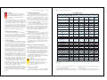
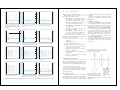
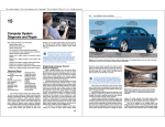
readings to normal readings. Figure 46-3 shows typical
vacuum gauge readings and explains what they mean.
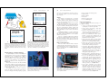
To help pinpoint problems that cannot be duplicated
in the shop, technicians will often mount the vacuumpressure gauge in the passenger compartment and run a
long hose to the vacuum fitting on the engine. This allows
the vehicle to be driven while checking for intermittent
vacuum or pressure problems. It also allows the technician to monitor engine and other system values under
load. See Figure 46-4.
Advanced Diagnostics
859
860
Section 8
Engine Performance
Vacuum Pump Tests
Vacuum
pump
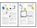
A hand vacuum pump is commonly used to check
vacuum-actuated devices and vacuum diaphragms. Since
vacuum diaphragms are made of rubber, which can rupture or leak, they are a common source of performance
problems.
To check a vacuum-actuated device, connect the
vacuum pump to the fitting. Pump the handle and see if
the device will hold a vacuum. If it leaks, the diaphragm
or the device should be replaced, Figure 46-5.
Turbo
wastegate
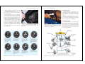
Figure 46-4. A pressure-vacuum gauge with a long section of
vacuum hose is needed for road testing. The vacuum gauge will
read turbocharger or supercharger boost pressures while
vehicle is driven.
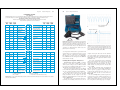
Figure 46-5. Always keep vacuum diaphragms in mind as a
potential source of trouble. They can rupture, leak air, and not
operate properly. A vacuum pump can be used to check the
condition of the vacuum diaphragm.
Diesel Engine Testers
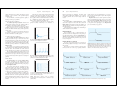
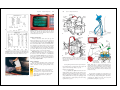
A diesel injection tester is a set of pressure gauges
and valves used to measure injection system pressure.
This tester will check fuel pump pressure and volume,
injector operation (out of engine), lubrication system
pressure, and other functions. If diesel injection pressures
are not within specifications, repairs or adjustments are
needed. Refer to Figure 46-6.
Manifold for
pressure gauges
To chassis
fuel system
Measuring transfer
pump pressure
Normal engine reading
Burned or leaky valves
Weak valve springs
Worn valve guides
Vacuum gauge should have
reading of 18-22 inches of
vacuum. The needle should
remain steady.
Burned valve will cause
pointer to drop every time
burned valve opens.
Vacuum will be normal at
idle but pointer will fluctuate
excessively at higher
speeds.
If pointer fluctuates excessively
at idle but steadies at higher
speeds, valves may be worn
allowing air to upset fuel
mixture.
Diesel
injection
pump
Checking inlet vacuum
Pump volume
measurement
Engine oil
pressure test
Measuring crankcase
pressure
Choked muffler
Intake manifold air leak
Vacuum will slowly drop to
zero when engine speed is
high.
If pointer is down 3 – 9
inches from normal at idle,
throttle valve is not closing
or intake gaskets are
leaking.
Carburetor or fuel
injection problem
A poor air-fuel mixture at idle
can cause needle to slowly
drift back and forth.
Figure 46-3. Typical vacuum gauge readings and possible causes. (Sonco)
Sticking valves
A sticking valve will cause
pointer to drop intermittently.
Fuel supply
pump pressure
*Note: Do not connect both ports of gauge
at once. When taking a reading (vacuum or
pressure) leave other port open to atmosphere.
Checking for
fuel return line
restriction
Figure 46-6. Diesel injection system testers can perform several tests. Note the various test connections. (Ford)