1
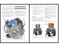
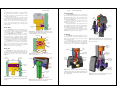
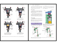
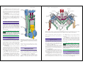
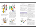
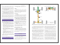
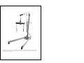
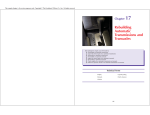
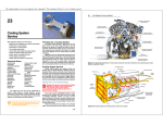
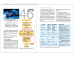
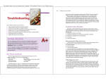
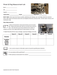
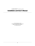
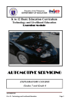
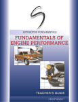
This sample chapter is for review purposes only. Copyright © The Goodheart-Willcox Co., Inc. All rights reserved.
Chapter
1
Review of Engine
Operation
After studying this chapter, you will be able to:
K List the major parts of an automotive engine.
K Explain the purpose of major engine parts and assemblies.
K Describe the relationship between the major parts of an engine.
K Summarize the four-stroke cycle.
K List and describe the related systems of an engine.
Know These Terms
BDC
Engine block
Piston pin
Camshaft
Engine valves
Piston rings
Charging system
Exhaust gas recirculation
system
Ports
Combustion
Computer system
Connecting rod
Control module
Cooling system
Crankcase
Crankshaft
Cylinder
Cylinder block
Cylinder head
Drive train
Emission control systems
Exhaust manifold
Positive crankcase ventilation
system
Four-stroke cycle
Spark plug
Fuel system
Starting system
Gasoline injection
TDC
Ignition system
Throttle valve
Intake manifold
Valve guides
Internal combustion engine
Valve seats
Lubrication system
Valve springs
Main bore
Valve train
Oil galleries
Water jackets
Piston
Water pump
9
10
Auto Engine Repair
This chapter provides a quick review of the operating
principles of a four-stroke-cycle, piston engine. The
interaction of basic engine components are discussed.
Related systems—cooling, lubrication, fuel, computer
control, and other systems—are explained. This review
will prepare you for later text chapters that discuss these
topics in much more detail.
This chapter uses words and illustrations to construct
a basic, one-cylinder engine. You will see how each part is
installed in the basic engine and learn how that part
performs an important function. Then, near the end of the
chapter, the systems that supplement engine operation and
protect the engine from damage are reviewed.
If you have completed an introductory course that
covered engine operation, you should still read through
this chapter to refresh your memory. If you are not familiar
with the operation of an engine, study this chapter carefully. This will let you catch up with the students that have
already had some training in engines.
Chapter 1
Review of Engine Operation
11
K The connecting rod connects the piston to the crankshaft.
Automotive Engine
An engine is the source of power for moving the vehicle and operating the other systems. Sometimes termed the
power plant, it burns a fuel (usually gasoline or diesel fuel)
to produce heat, expansion of gasses, pressure, and resulting part movement.
Since a vehicle’s engine burns fuel inside of itself, it is
termed an internal combustion engine. As you will learn,
the arrangement of an engine’s parts allows it to harness
the energy of the burning fuel.
Figure 1-1 illustrates the major parts of a modern,
multi-cylinder engine. Study them as they are introduced:
K The block is the supporting structure for the engine.
K The piston slides up and down in the block.
K The piston rings seal the space between the block and
sides of the piston.
Camshaft
Intake
manifold
Valve spring
K The crankshaft converts the up and down action of
the piston into rotary motion.
K The cylinder head fits over the top of the block and
holds the valves.
K The valves open and close to control fuel entry into
and exhaust exit from the combustion chamber.
K The combustion chamber is a cavity formed above
the piston and below the cylinder head for containing
the burning fuel.
K The camshaft opens the valves at the proper time.
K The valve springs close the valves.
K The timing belt or chain turns the camshaft at one-half
of the engine speed.
Engine Block
The engine block, also called the cylinder block,
forms the framework or “backbone” of an engine. This is
because many of the other components of an engine fasten
to the block. Cast from iron or aluminum, the block is the
largest part of an engine. Figure 1-2 shows a cutaway view
of a basic engine block. Note the part names.
A cylinder is a large hole machined through the top of
the engine block. The piston fits into the cylinder. During
engine operation, the cylinder, also called the cylinder
bore, guides the piston as it slides up and down. The cylinder is slightly larger than the piston to produce a clearance
(space) between the two parts.
Main caps are bolted to the bottom of the block. They
hold the crankshaft in place and form the bottom half of
the main bore.
The main bore is a series of holes machined from the
front to the rear of the block. The crankshaft fits into these
holes. With the engine running, the crankshaft spins or
rotates in the main bore.
The deck is a flat surface machined on the top of the
block for the cylinder head. The head is bolted to the deck.
Coolant and oil passages in the deck align with openings
in the cylinder head.
Coolant passages, or water jackets, surround the
cylinders and combustion chamber. They are hollow areas
inside the block and head for coolant. Coolant circulated
through the water jackets removes the heat generated by
the fuel burning in the cylinders.
The crankcase is the lower area of the block. The
crankshaft spins inside the crankcase.
Piston
The piston converts the pressure of combustion into
movement. See Figure 1-3. Combustion is the burning of
Deck
Valve
Cylinder
head
Water
jacket
Piston slides
up and down
in cylinder
Cylinder
Timing
chains
Cylinder
block
Crankcase
Main
bore
Block
Combustion
chamber
Exhaust
manifold
Crankshaft
pulley
Piston
Crankshaft
Oil pan
Piston rings
Connecting rod
Figure 1-1. Study the general location of parts in an engine.This will help you while reviewing the operation of an engine in this chapter. (Ford)
Main caps
Main bolts
Figure 1-2. The block is the framework for holding the other
engine components. Note the parts of the block. This is a
simplified, one-cylinder engine.
Figure 1-3. The piston fits into a cylinder bored through the
block. The piston slides up and down during engine operation
acting as a pumping and power-producing element.
12
Auto Engine Repair
Combustion
pressure
Ring
tension
Compression
ring
The piston rings fit into grooves machined into the
sides of the piston. These rings keep combustion pressure
from entering the crankcase and engine oil from entering
the combustion chamber. Look at Figure 1-4.
The compression rings seal the clearance between
the block and piston. They are normally the two upper
piston rings. Their job is to contain the pressure formed in
the combustion chamber, Figure 1-5. Without compression rings, pressure would blow past the outside diameter
of the piston and into the lower area of the engine block.
The oil ring fits into the lowest groove in the piston. It
is designed to scrape excess oil from the cylinder wall to
keep it from being burned in the combustion chamber,
Figure 1-6. If oil enters the area above the piston and
burns, blue smoke blows out of the tailpipe.
Review of Engine Operation
13
Connecting Rod
fuel, which results in expanding gas inside the cylinder.
The piston transfers the pressure of combustion to the
piston pin, connecting rod, and crankshaft. It also holds
the piston rings and piston pin.
During engine operation, the piston slides up and
down in the cylinder at tremendous speeds. At a vehicle
speed of about 55 mph (88 km/h), the piston can accelerate from zero to 60 miles an hour and then back to
zero in one movement from top to bottom in the
cylinder. This places tremendous stress on the piston and
its related parts.
Piston Rings
Chapter 1
Cylinder
wall
Piston
Figure 1-5. The compression rings use combustion pressure to
help seal against the cylinder wall. This keeps pressure in the
combustion chamber and out of the crankcase.
Cylinder wall
Piston
Ring
groove
Oil control
ring
The connecting rod transfers the force of the piston to
the crankshaft. It is fastened to the piston pin at the top and
the crankshaft at the bottom. It also causes piston movement on nonpower-producing events (up and down piston
movements). See Figure 1-8.
The small, top end of the connecting rod has a hole
machined in it for the piston pin. The top of the rod
extends inside of the piston.
The big, bottom end of the connecting rod fits around
the crankshaft journal. It has a removable cap that allows
the installation and removal of the rod-piston assembly.
Special rod bolts and nuts hold the cap in place.
As discussed in later chapters, bushings are normally
installed in the small end of the rod. Rod bearings are
installed in the big end of the connecting rod.
Crankshaft
A piston pin, also called a wrist pin, allows the connecting rod to swing back and forth inside the piston. The
pin fits through a hole machined in the piston and through
a hole in the upper end of the connecting rod. Refer to
Figure 1-7.
Piston
clearance
Piston
clearance
Oil film
Oil to crankcase
Figure 1-6. Oil rings act as a scraper to keep oil out of the combustion chamber. (Deere & Co.)
Piston
head
Piston
diameter
Figure 1-9. The crankshaft takes the reciprocating motion of
the piston and produces rotary motion for vehicle’s drive train
and accessory system.
Connecting
rod I-beam
Big end
for rod
bearing
Piston at
bottom dead
center
Rod bolt
Rod cap
Rod and
its crankshaft
journal up
Piston
pin
Compression
rings
Piston
Piston
pin bore
Oil ring
Figure 1-4. The clearance between the piston and cylinder
allows the piston to move freely in the cylinder. Rings seal the
clearance.
Counterweight
Piston
pin
Rod nut
Piston pin
Snout
Piston at
top dead
center
Small end
Ringlands
Flywheel
flange
Main
journals
The crankshaft converts the up and down (reciprocating) movement of the connecting rod and piston into rotary
motion. The rotary motion is used to power gears, chains,
belts, and the drive train.
The crankshaft fits into the main bore of the engine
block, as shown in Figure 1-9. It mounts on the main bearings and is free to spin inside the block. The connecting
rods are attached to the crankshaft journals. Figure 1-10
Escaping
oil
Piston Pin
Rod
journal
Connecting
rod
Swinging action
Figure 1-7. The piston pin fits into a hole bored in the piston.
The pin attaches the piston to the connecting rod.
Figure 1-8. The connecting rod links the piston and crankshaft
together. The large end has a removable cap that allows the rod
to be bolted around the crankshaft journal. The small end has a
hole for the piston pin.
Rod and its
crankshaft
journal down
Figure 1-10. Note how the crankshaft changes the reciprocating motion of the piston into rotary motion.
14
Auto Engine Repair
shows how the crankshaft changes the reciprocating (up
and down) motion of the piston and connecting rod into a
rotary motion.
The engine flywheel is a very heavy, round disk
mounted to the back of the crankshaft. It helps to keep the
crankshaft spinning between power strokes and smooth
engine operation. It also holds a large gear used by the
starter.
TDC and BDC
The abbreviation TDC stands for top dead center. This
is the point of travel where the piston is at its highest point
in the cylinder. The abbreviation BDC stands for bottom
dead center. This is the point of travel where the piston is
at its lowest point in the cylinder. Refer to Figure 1-11.
Crankshaft
Piston
One-half
revolution
180°
One stroke
Review of Engine Operation
15
Cylinder Head
The cylinder head is bolted to the top of the block
deck to enclose the top of the cylinders and form the top
of the combustion chamber, Figure 1-12. Like the block,
the cylinder head contains water jackets for cooling and
oil passages for lubricating moving parts on or in the
cylinder head.
Valve guides are machined through the top of the
head for the valves. The valves slide up and down in these
guides.
Cylinder head ports are passages for the air-fuel
mixture to enter the combustion chamber and for exhaust
gasses to flow out of the engine. These are located in the
cylinder head.
Valve seats are machined in the opening where the
ports enter the combustion chamber. The valves close against
the seats to make a leakproof seal at high temperatures.
Engine Valves
Top dead
center
(TDC)
Chapter 1
Engine valves control the flow into and out of the
engine cylinder or combustion chamber. They fit into the
cylinder head, operate inside the valve guides, and close
on the valve seats. Valve springs fit over the top end of the
valves to keep the valves in a normally closed position,
Figure 1-13.
Figure 1-14 shows how a valve opens and closes the
ports in the cylinder head. When the valve slides down,
the valve head moves away from the valve seat and the
port is opened. When the valve slides up, the valve head
moves toward the valve seat until the valve face makes
contact with the valve seat. This seals the combustion
chamber from the port.
Cylinder head
Valve guides
Exhaust
port
TDC
Air-fuel
mixture
Valve springs
Exhaust
port
Intake
port
Exhaust
valve
Intake
valve
Intake
valve open
Figure 1-13. Valves fit into guides in the cylinder head. Valve
springs hold the valves closed. The valves seal against valve
seats in the head to close off ports from the combustion chamber.
There are two types of valves—intake and exhaust.
The intake valve is the larger valve and it allows a fuel
charge to flow into the cylinder. The exhaust valve is the
smaller valve and it opens to let burned gasses (exhaust)
out of the cylinder. Figure 1-15 shows how the air-fuel
mixture flows through the intake port, past the valve, and
into the combustion chamber when the valve is open.
Four-Stroke Cycle
The four-stroke cycle needs four up or down piston
movements, or strokes, to produce one complete cycle.
Every two up and two down strokes of the piston results
Cylinder
head
Valve guide
Intake
port
Water
jacket
Exhaust
valve seat
Port
Intake
valve seat
Valve
face
Valve
head
Figure 1-14. Study the valve action. When the valve slides
open, the valve face is lifted off of the valve seat. This opens the
port to the combustion chamber and gasses are free to enter or
exit the cylinder.
Connecting
rod
Figure 1-11. TDC is when the piston is at the top of its stroke.
BDC is when the piston is at the bottom of its stroke. One stroke
is the piston movement from TDC to BDC or vice versa. (Ford)
Margin
Valve
seat
Figure 1-12. The cylinder head is bolted to the top of the block.
It forms a cover over the cylinder. The head also holds the
valves that control flow into and out of the cylinder.
Figure 1-15. Note the action as the intake valve opens.
Downward movement of the piston forms a vacuum in the
cylinder. Atmospheric pressure pushes the air-fuel charge into
the cylinder. (Ford)
in one power-producing cycle. Two complete revolutions
of the crankshaft are needed to complete one four-stroke
cycle. Automotive engines, both gas and diesel, are
four-stroke-cycle engines.
The four strokes are intake, compression, power,
and exhaust. With the engine operating, these strokes
happen over and over very rapidly. At idle, an engine
might be running at 800 revolutions per minute (rpm),
which means the crankshaft rotates 800 times in one
minute. Since it takes two complete revolutions of the
crankshaft to complete a four-stroke cycle, an engine
completes 400 four-stroke cycles per minute at idle. In
other words, the piston must slide up 800 times and
down 800 times per minute. You can imagine how fast
these events are happening at highway speeds!
Intake Stroke
BDC
Bottom
dead center
(BDC)
Port in
cylinder head
A gasoline engine’s intake stroke draws air and fuel
into the combustion chamber. Figure 1-16A shows the
basic action during the intake stroke. Study the position of
the valves and movement of the piston. The piston slides
down to form a vacuum (low pressure area). The intake
valve is open and the exhaust valve is closed. Atmospheric
pressure (outside air pressure) pushes the air-fuel charge
into the vacuum in the cylinder. This fills the cylinder with
a burnable mixture of fuel and air.
Compression Stroke
The compression stroke squeezes the air-fuel mixture
to make it more combustible. See Figure 1-16B. Both the
intake and exhaust valves are closed. The piston slides up
and compresses the mixture into the small area in the combustion chamber.
16
Auto Engine Repair
Air-fuel mixture
pulled into
cylinder
Exhaust
valve
closed
Chapter 1
Review of Engine Operation
17
For proper combustion (burning), it is very important
that the valves, rings, and other components do not allow
pressure leakage out of the combustion chamber. Leakage
during the compression stroke may prevent the mixture
from igniting and burning on the power stroke.
The camshaft opens the valves and allows the valve
springs to close the valves at the proper times. The
camshaft has a series of lobes (egg-shaped bumps) that act
on the valves or valve train to slide the valve down in its
guide. See Figure 1-18.
Power Stroke
Exhaust
valve
closed
Intake valve
open
Intake valve
closed
Pressure formed
on fuel charge
Piston and
rod moving
down
A—Intake Stroke
Piston and
rod moving up
Both valves are closed and the piston
slides up. This compresses the air-fuel
charge and prepares it for combustion.
Spark
plug fires
Intake valved
closed
Exhaust valve
closed
Intake
valve
closed
Burned
gasses
pushed from
cylinder
The exhaust stroke pushes the burned gasses out of
the cylinder and into the vehicle’s exhaust system. See
Figure 1-16D. The intake valve remains closed, but the
exhaust valve is open. Since the piston is now moving up,
the burned gasses are pushed out of the exhaust port to
ready the cylinder for another intake stroke.
Valve Train
The valve train operates the engine valves. It times
valve opening and closing to produce the four-stroke
cycle. Basic valve train parts are shown in Figure 1-17.
Air-fuel mixture
burns, expands,
and forms
pressure
Exhaust valve
open
Piston and
rod pushed
down to turn
crankshaft
Camshaft
Exhaust Stroke
B—Compression Stroke
The piston slides down with the intake valve
open and the exhaust valve closed. The
air-fuel charge is pulled into the cylinder.
Cam lobes
The air-fuel mixture is ignited and burned during the
power stroke to produce gas expansion, pressure, and a
powerful downward piston movement. See Figure 1-16C.
Both valves are still closed. The spark plug fires and the
fuel mixture begins to burn.
As the mixture burns, it expands and builds pressure in
the combustion chamber. Since the piston is the only part
that can move, it is thrust downward with several tons of
force. This downward thrust pushes on the connecting rod
and crankshaft forcing the crankshaft to turn. The power
stroke is the only stroke that does not consume (use) energy.
Rocker arm
pushes
down
Pivot point
Piston
and rod
moving up
Figure 1-18. The lobes on the camshaft act on the valves or
valve train to open and close the valves. As shown here, the
camshaft fits into the cylinder head on many engines. This lets
it operate directly on valves without using push rods.
Rocker arm pushed
up by spring
Spring
Valve closed
on seat
C—Power Stroke
The spark plug fires and the fuel begins to
burn. The heat of combustion causes
expansion of the gasses and creates
pressure. This pushes the piston down with
tremendous force to spin the crankshaft.
Push rod
D—Exhaust Stroke
The piston slides up with the intake valve
closed and the exhaust valve open. This
pushes the exhaust gasses out of the
cylinder so a fresh charge can enter.
Figure 1-16. Review the four-stroke cycle. You must be able to visualize these events to be a competent engine technician.
Valve
pushed
off seat
Cam lobe
touches
lifter
Valve open
Lifter
(tappet)
Lobe away
from lifter
Valve closed
Figure 1-17. The camshaft operates the valve train. When the cam lobe rotates into a lifter, the valve is opened. When a lobe moves
out of a lifter, the valve spring closes the valve. (Ford)
18
Auto Engine Repair
In Figure 1-17, note how the cam lobe acts on the
valve train. When the lobe moves into the lifter, the lifter,
pushrod, and one side of the rocker arm are pushed up.
This opens the valve. When the lobe rotates away from the
lifter, the valve spring pushes the valve and other parts into
the closed position.
Camshaft timing is needed to ensure that the valves
properly open and close in relation to the crankshaft.
Either a belt, chain, or set of gears is used to turn the
camshaft at one-half of the crankshaft speed and keep the
camshaft in time with the crankshaft. Figure 1-19 shows
how a timing belt is used to operate the camshaft on our
basic engine.
Note: With multiport fuel injection, the fuel
is injected into the airstream at the port.
However, the fuel is injected into the
airstream at the beginning of the intake manifold
(in the throttle body) with throttle body injection.
Review of Engine Operation
19
Air
Camshaft
sprocket
Throttle body
Intake manifold
Intake
runners
Valve
cover
Timing
belt
Exhaust
port
Exhaust
manifold
Adjuster
pulley
Figure 1-20. This is a cutaway of an engine. Note the intake and exhaust manifolds. Ports in the intake manifold connect to the intake
ports in the cylinder head. The exhaust manifold is bolted over the exhaust ports in the cylinder head. (General Motors)
Crankshaft
sprocket
bearings, camshaft bearings, and valve train components.
These are high-friction points in the engine and need oil
for protection.
Cooling System
The cooling system is needed to carry the heat of
combustion and friction away from the engine. Without a
cooling system, the piston, valves, cylinder, and other parts
could be ruined in a matter of minutes. The head and
block could also crack from the tremendous heat.
Basically, a cooling system consists of a radiator, water
pump, fan, thermostat, water jackets, and connecting
hoses, Figure 1-21.
The water pump circulates an antifreeze and water
solution through the water jackets, hoses, and radiator. It is
often driven by a fan belt running off of the crankshaft pulley, but may be driven by an electric motor. The coolant
(antifreeze-water solution) picks up heat from the metal
parts of the engine and carries it to the radiator.
The radiator transfers heat from the coolant to the
outside air. A fan is used to pull air through the radiator.
Large radiator hoses connect the radiator to the engine.
The thermostat is a temperature-sensing valve that
controls the operating temperature of the engine. When
the engine is cold, the thermostat blocks coolant flow
through the radiator and speeds warm-up of the engine.
Fuel injector
Intake port
Intake and Exhaust Manifolds
The intake manifold carries the air-fuel mixture into
the cylinder head intake ports. It normally is bolted to the
cylinder head. Ports in the intake manifold match the
intake ports in the cylinder head. The exhaust manifold, as
its name implies, carries burned gasses from the cylinder
head exhaust port to the other parts of the exhaust system.
Figure 1-20 shows the basic action of the intake and
exhaust manifolds.
Chapter 1
Figure 1-19. The camshaft is turned at one-half of engine
speed. A timing belt is the most common method of turning the
camshaft in time with the crankshaft rotation. Note the part
names.
When the engine is warm, the thermostat opens to allow
coolant to circulate through the radiator, thus removing
heat from the engine.
Lubrication System
The lubrication system circulates engine oil to highfriction points in the engine. Without oil, friction will result
in wear, scoring, and damage to parts very quickly. The
lubrication system basically consists of an oil pump, oil
pickup, oil pan, and oil galleries. See Figure 1-22.
The oil pump is the “heart” of the lubrication system
because it circulates oil through the oil galleries. The oil
galleries are small passages that lead to the crankshaft
Ignition System
An ignition system is needed on a gasoline engine to
ignite and burn the air-fuel mixture. It must increase
battery voltage enough to produce a high-voltage electric
arc, or “spark,” at the tip of each spark plug in the combustion chamber. Refer to Figure 1-23.
A fundamental ignition system consists of a spark
plug, plug wire, ignition coil, switching device, and power
source. On many late-model vehicles, the ignition coil is
mounted directly on top of the spark plug eliminating the
need for a spark plug wire.
The switching device in the ignition system is an electronic control unit that makes and breaks electrical current
flow to the ignition coil(s). Ignition coil operation is timed
with crankshaft rotation so that the spark occurs in the
combustion chamber at the end of the compression stroke.
The ignition coil is used to step up battery voltage to
over 60,000 volts. This is enough voltage to make the electricity jump the spark plug gap. The ignition coil fires every
time the switching device stops current flow from the
battery, Figure 1-23. This causes the magnetic field in the
coil to collapse and induce a higher voltage in the coil’s
output wire.
The spark plug is the “match” that starts the air-fuel
mixture burning in the combustion chamber. When
ignition coil fires and sends current through the spark plug
wire, an electric arc (spark) forms at the tip of the spark
plug. This makes the fuel and air start to burn, producing
the power stroke.
Note: Older ignition systems used a
mechanical switching device called
points. Ignition systems with points have
not been used on production vehicles since the
mid 1970s. If you encounter this type of ignition
system, refer to the appropriate service manual for
service procedures.
Starting System
The starting system turns the engine crankshaft until
the engine can begin running on its own power. It uses a
battery, ignition switch, high-current relay, and electric
motor to rotate the crankshaft, Figure 1-24.
20
Auto Engine Repair
Chapter 1
Spark plug
wire
Hot coolant
Radiator
Battery
Spark
plug
Fan
Airflow to
remove heat
from coolant
Engine
water
jacket
Combustion
Electronic
control unit
or switching
device
Cooled
coolant
Fan belt
Figure 1-21. A cooling system is needed to remove heat from
the engine and prevent severe engine damage. Water jackets
allow coolant to flow around the cylinders and through the
cylinder head. A water pump circulates coolant through the
system. The radiator dissipates heat into the outside air. A fan
pulls air through the radiator. (DaimlerChrysler)
Oil to
valve train
Speed sensing
device or
pickup coil
Figure 1-23. The ignition system is used on a gasoline engine
to ignite the fuel in the combustion chamber. A coil produces
high voltage for the spark plug. When the switching device
breaks the flow of current to the coil, the coil and spark plug fire
to ignite the fuel.
The battery stores chemical energy that can be
changed into electrical energy. When the driver turns ignition switch (start switch), the solenoid (high-current relay)
sends battery current to the starter motor. The starter
motor has a small gear that engages a large gear on the
crankshaft flywheel. The motor has enough torque (turning
force) to spin the flywheel, and thus the crankshaft, until
the engine starts and runs. Then, the driver releases the
ignition key and deactivates the starting system.
Oil filter
Wiring harness
Main fuse
Oil
dipstick
Oil gallery
Gasoline Injection System
The charging system is needed to recharge (re-energize)
the battery after starting system or other electrical system
operation. The battery can become discharged (run down)
after only a few minutes of starter motor operation. The
charging system also provides all of the vehicle’s electrical
needs while the engine is running. Basically, the charging
system consists of the alternator and a voltage regulator.
Look at Figure 1-25.
The alternator produces the electricity to recharge the
battery. It is driven by a belt from the engine crankshaft
pulley. The alternator sends current through the battery to
reactivate the chemicals in the battery. This again prepares
the battery for starting or other electrical loads.
The voltage regulator controls the electrical output of
the alternator. It ensures that about 14.5 volts are produced
by the alternator. Current then flows back into the battery,
since battery voltage is only about 12.5 volts.
Trigger wheel
Crankshaft pulley
21
Charging System
Ignition coil
Water
pump
Review of Engine Operation
Starter motor
Flywheel
ring gear
Fuel System
The fuel system must meter the right amount of fuel
(usually gasoline or diesel oil) into the engine for efficient
combustion under different conditions. At low speeds, it
must meter a small amount of fuel into the airstream. As
engine speed and load increase, the fuel system must
meter more fuel into the airstream. The fuel system must
also alter the fuel metering with changes in engine temperature and other variables.
There are two basic types of automotive fuel systems
in current use—gasoline injection and diesel injection. A
third type of fuel system—carburetion—has not been
commonly used since the mid 1980s.
Ignition
switch
Charging system
wiring harness
Main fuse
Negative or
ground
cable
Diesel Injection System
Voltage
regulator
Oil pump
Positive
battery
cable
Oil to crank
and camshaft
Oil pan
Figure 1-22. The lubrication system prevents excess friction
that may damage the engine. Note the part names.
(DaimlerChrysler)
Charge
indicator
Starter cable
Alternator
Starter solenoid
Figure 1-24. The starting system rotates the crankshaft until the
engine starts. A powerful electric starter motor has a gear that
meshes with the gear on the engine flywheel. A solenoid makes
the electrical connection between the battery and the starter
motor when the ignition key is turned to the start position. (Honda)
Battery
A gasoline injection system uses fuel pump pressure
to spray fuel into the engine intake manifold, usually near
the cylinder head’s intake port. A basic system is pictured
in Figure 1-26.
An electric fuel pump forces fuel from the fuel tank to
the fuel injector. A constant pressure is maintained at the
injector. The fuel injector is simply an electrically-operated
fuel valve. When energized by the control module, it
opens and squirts fuel into the intake manifold or the combustion chamber. When not energized, it closes and prevents fuel entry into the engine.
Modern gasoline injection systems open the injector
when the engine intake valve opens. Then, fuel is partially
or completely forced into the combustion chamber by
pump pressure. This helps control how much fuel enters
the cylinder and also increases combustion efficiency, as
you will learn in later chapters.
A control module (computer) is used to regulate when
and how long the injector opens. It uses electrical information from various sensors to analyze the needs and operating
conditions of the engine. The engine sensors monitor
various operating conditions, such as engine temperature,
speed, load, and so on. In this way, the computer can determine whether more or less fuel is needed and whether the
injector should be opened for a longer or shorter period of
time based on the current operating conditions.
A throttle valve controls airflow, engine speed, and
engine power. It is connected to the accelerator pedal. When
the pedal is pressed, the throttle valve opens to allow more air
into the combustion chambers. In turn, the control module
holds the injectors open for a longer period of time, allowing
more fuel into the combustion chamber. The increase in air
and fuel results in an increase in engine power output.
As the accelerator pedal is released, the throttle valve
closes, reducing the amount of air allowed into the
combustion chamber. The control module, in turn, reduces
the amount of time the injectors are open, thus reducing
the amount of fuel released into the injection chamber.
The decrease in air and fuel results in a decrease in engine
power output.
Alternator
belt
Figure 1-25. The charging system recharges the battery and
provides the vehicle’s electrical needs while the engine is
running. (Honda)
A diesel injection system forces fuel directly into the
engine’s combustion chamber, as shown in Figure 1-27.
The heat resulting from highly compressed air, not an electric spark plug, ignites and burns the fuel. When the intake
valve opens, a full charge of air is allowed to flow into the
cylinder. Then, on the compression stroke, the air is
squeezed until it is at a high temperature. As soon as the
fuel is injected into the hot air, the fuel burns and expands.
A diesel injection system basically consists of an
injection pump, injector, and glow plug system. The
injection pump is a high-pressure, mechanical pump. It is
powered by the engine and forces fuel to the diesel
injector under very-high pressure. A conventional fuel
pump feeds fuel from the tank to the injection pump.
22
Auto Engine Repair
Chapter 1
Review of Engine Operation
Fuel injector (fuel valve)
sprays fuel toward intake
valve when open
23
Air enters filter
Fuel line
Carburetor
Spark plug
ignites mixture
Low-pressure
mechanical fuel
pump
Air enters
Throttle
valve
Electric
fuel pump
Gasoline
from tank
Wires to
engine
sensors
Control module
Fuel pulled into
airstream by vacuum
Throttle controls airflow
and engine speed
Fuel
from tank
Mixture ignited
by spark plug
Figure 1-28. Carburetion systems are not used on passenger vehicles, but are still used on small gas engines. In this type of system, airflow into engine pulls fuel out of carburetor’s fuel bowl. A mechanical fuel pump fills the fuel bowl with fuel, but does not force
the fuel into the intake manifold.
Air-fuel mixture flows
to cylinder
Figure 1-26. Gasoline injection uses pressure from an electric fuel pump to spray fuel into engine intake manifold through fuel
injectors. A throttle valve is used to control the airflow into the engine.
Computer System
The diesel injector is simply a spring-loaded valve. It
is normally closed and blocks fuel flow. However, when
the injection pump forces fuel into the injector under high
pressure, the injector opens. The fuel is sprayed directly
into the combustion chamber or a precombustion chamber. This is called a direct injection system.
Note in Figure 1-27 that a diesel does not have a
throttle valve or a spark plug. Engine power and speed are
controlled by the injection pump, which is controlled by a
control module. The more fuel injected into the combustion chamber, the more speed and power are produced by
the engine. As less fuel is injected into the combustion
chamber, engine speed and power decrease.
A glow plug system is used to aid cold starting of a
diesel engine. The glow plug is an electric heating element
that warms the air in the combustion chamber. This helps
the air become hot enough to start combustion until the
heat from engine operation can warm the incoming air.
Carburetion Fuel System
Instead of injecting fuel into the airstream or combustion
chamber, a carburetion system uses engine vacuum (suction) to
pull fuel into the engine, Figure 1-28. Airflow through the carburetor and the vacuum created by the engine’s intake stroke draw
fuel out of the carburetor’s fuel bowl. As the throttle valve is
opened, more air flows through the carburetor and, thus, more
fuel flows into the airstream. A low-pressure, mechanical fuel
pump draws fuel from the tank and delivers it to the carburetor’s
fuel bowl. The carburetion system is not currently used on latemodel vehicles but is still found on small gas engines.
A computer system is used to increase the overall efficiency of a vehicle. The computer, or control module, can
control the ignition system, fuel system, transmission or
transaxle, emission control systems, and other systems.
Figure 1-29 shows a diagram of a simplified vehicle computer system. A modern vehicle may have several control
modules.
To understand how a vehicle’s computer control
system works, think of the human body’s central nervous
system. For example, if your finger touches a hot stove, the
nerves (sensors) in your hand send a signal to your brain.
Your brain (control module) analyzes these signals and
decides that you are in pain. Your brain (control module)
quickly activates your muscles (actuators) to pull your
hand away from the hot stove. A computer control system
works in the same manner. It controls actions based on
sensory inputs. For simplicity, a vehicle’s computer control
system can be divided into three subsystems: sensor,
control, and actuator.
The sensor subsystem checks various operating
conditions using sensors. A sensor is a device that can
Knock sensor
Mass airflow sensor
Fuel injectors
Mechanical injection nozzle sprays fuel
into combustion chamber
Air enters
Oxygen sensor
Injection line
Manifold absolute
pressure sensor
Fuel ignites as it
touches hot air
Intake air
temperatue sensor
Fuel pressure regulator
Control module
Engine coolant
temperature sensor
High-pressure
mechanical pump
Engine speed sensor
No throttle valve
Fuel pump
Only air flows past intake valve
and into combustion chamber
Air compressed so tight
it becomes red hot
Diesel fuel
from tank
Figure 1-27. Diesel injection is primarily mechanical. A mechanical injection pump forces fuel into a spring-loaded injector nozzle. The
pressure opens the injector and fuel sprays directly into combustion chamber. A diesel does not use a throttle valve or spark plug.
Throttle position sensor
Catalyst monitor
Figure 1-29. This is a simplified diagram of the sensor, control, and actuator subsystems of a computer control system for fuel
injector operation.
24
Auto Engine Repair
change its electrical signal based on a change in a condition. Sensors might measure intake manifold vacuum,
throttle opening, engine speed, transmission gear position,
road speed, turbocharger boost pressure, and other conditions. The sensing system sends different electrical current
values back to the control module.
The control subsystem looks at the inputs from the
sensors and determines what actions need to take place. A
control module, or computer, contains miniaturized electrical
circuits that collect, store, and analyze information. The control module then provides signals to the actuator subsystem.
The actuator subsystem serves as the “hands” of the
computer system. Based on signals from the control module, this system moves parts, opens injectors, closes the
throttle, turns on the fuel pump, and performs other tasks
needed to increase the overall efficiency of the vehicle.
Electric motors, solenoids or relays, and switches are the
actuators. The actuators turn on or off, open or close, or
change position based on the signals from the control
module. This is discussed in detail later in this textbook.
Emission Control Systems
Emission control systems are designed to reduce the
amount of harmful chemicals and compounds (emissions)
that enter the atmosphere from a vehicle. There are several
types of emission control systems:
K PCV. The positive crankcase ventilation system pulls
fumes from the engine crankcase into the intake manifold
so they can be burned before entering the atmosphere.
K Evaporative emissions control. This system uses a
charcoal-filled canister to collect and store gasoline
fumes from the fuel tank when the engine is not
running. Air is drawn through the canister and into
the intake manifold while the engine is running so the
collected fumes are burned.
K EGR. The exhaust gas recirculation system injects
exhaust gasses into the engine to lower combustion
temperatures and reduce one form of pollution in the
engine exhaust.
K Air injection. This system forces air into the exhaust
stream leaving the engine to help burn any unburned
fuel that exits the combustion chamber.
K Catalytic converter. This device chemically converts
byproducts of combustion into harmless substances.
Many of these systems work together, all reducing
their share of harmful emissions. The computer also plays
an important part in reducing pollution. It improves the
efficiency of many systems.
Drive Train
The drive train uses power from the engine to turn the
vehicle’s drive wheels. Drive train configurations vary, but
Chapter 1
Review of Engine Operation
can generally be classified as rear-wheel drive or frontwheel drive. Figure 1-30 shows simplified drive trains.
25
Transmission
Clutch
Engine
Clutch
The clutch allows the driver to engage or disengage
the engine power from the drive train. It is mounted onto
the engine flywheel between the engine and transmission
or transaxle. A clutch is needed when the vehicle has a
manual transmission. A vehicle with an automatic transmission does not have a clutch.
Engine
Clutch
Differential
Manual transaxle
Front
drive axle
Manual
transmission
Transmission
The transmission uses a series of gears to allow the
amount of torque going to the drive wheels to be varied. The
driver can shift gears to change the ratio of crankshaft revolutions to drive wheel rotation. When first accelerating, more
torque is needed to get the vehicle moving. Then, at higher
road speeds, less torque is needed to maintain road speed.
Engine speed also needs to be reduced at highway speeds.
A manual transmission is shifted by hand. Levers,
cables, or rods connect the driver’s shift lever to the internal parts of the transmission. An automatic transmission
uses a hydraulic (fluid pressure) system to shift gears. A
torque converter (fluid clutch) and special planetary gear
sets provide automatic operation. However, the driver
must manually change the shift lever position to change
from forward to reverse.
A transaxle is a transmission and a differential (axle
drive mechanism) combined into one housing. It is
commonly used with front-wheel-drive vehicles, but may
also be found on rear-engine, rear-wheel-drive vehicles. A
transaxle may be manual or automatic.
Drive Shaft and Drive Axle
A drive shaft is used with a front-engine, rear-wheeldrive vehicle. It connects the transmission to the differential.
A drive axle connects the differential to the drive hubs
or wheels. On most rear-wheel-drive vehicles, the drive
axle is a solid steel shaft. On vehicles with a transaxle, the
drive axle is a flexible shaft extending from the transaxle to
the front wheel hubs.
Summary
This chapter reviewed the basic operation of a fourstroke-cycle, piston engine. The engine found in most
vehicles is called an internal combustion engine because it
burns fuel inside of combustion chambers.
The cylinder block holds the other parts. The piston
and connecting rod transfer combustion pressure to the
crankshaft. The crankshaft converts the up and down
action of the piston into rotary motion.
Drive shaft
Differential
A
Rear
drive axle
Dead axle
B
Figure 1-30. The drive train uses engine power and crankshaft rotation to turn the vehicle’s drive wheels. A—A front-engine,
rear-wheel-drive vehicle. B—A front-engine, front-wheel-drive vehicle. Note the differential and transmission in one housing.
The cylinder head is bolted on top of the cylinder
block. It contains the valves that control flow into and out
of the cylinder. The camshaft operates the valves so that
they open and close to correspond to piston action, producing the four-stroke cycle.
The intake stroke draws air-fuel mixture into the
engine. The compression stroke squeezes the mixture and
readies it for burning. The power stroke ignites the mixture
and the expanding gasses push the piston down with
tremendous force. The exhaust stroke purges the burned
gasses to prepare the cylinder for another intake stroke.
Every two crankshaft revolutions complete one fourstroke cycle. Thus, one power stroke is produced every
two crankshaft revolutions. The flywheel helps keep the
crankshaft spinning on the nonpower-producing strokes
and smoothes out engine operation.
Various systems are needed to keep the engine running. The cooling system removes excess combustion heat
and prevents engine damage. The lubrication system also
prevents engine damage by reducing friction between
moving engine parts.
The ignition system is needed on a gasoline engine to
ignite the fuel and start it burning. A diesel engine uses
high-compression-stroke pressure to heat the air in the
cylinder enough to start combustion, instead of an electric
spark. Also, a diesel does not use a throttle valve to control
engine speed. The amount of fuel injected into the cylinder controls engine speed and power output.
The two types of fuel systems in use today are
gasoline injection and diesel injection. Modern fuel injection increases fuel economy over older fuel systems by
closer control of the fuel use by each cylinder. Carburetion
is not used today.
The starting system uses a powerful electric motor to
turn the engine flywheel until the engine can run on its own
power. The charging system recharges the battery and supplies electricity to the vehicle while the engine is running.
A vehicle’s computer system is similar to the human
body’s central nervous system. The computer system
monitors various conditions by analyzing input signals
from sensors. Then, the control module (computer) determines what action should be taken to maintain maximum
efficiency. Based on this, the control module sends signals
to actuators that control the operation of the fuel system,
ignition system, transmission, and other devices.
Emission control systems reduce the amount of harmful pollutants that enter the atmosphere. Some emission
control systems prevent fuel vapors from evaporating into
26
Auto Engine Repair
the air. Others ensure complete combustion of fuel that
leaves the combustion chamber and others just increase
engine efficiency to reduce air pollution.
The drive train transfers engine power to the drive
wheels. Both front-wheel and rear-wheel drive are found
on today’s vehicles. Front-wheel-drive vehicles have a
transaxle, which is the transmission and differential combined in a single unit.
Review Questions—Chapter 1
Please do not write in this text. Write your answers on
a separate sheet of paper.
1. The _____ is the main supporting structure of an
engine.
2. These hold the crankshaft in the bottom of the engine
block.
(A) Cam bearings.
(B) Main caps.
(C) Decks.
(D) Rod bearings.
ASE-Type Questions—Chapter 1
1. Technician A says an engine’s timing belt turns the
camshaft at one-half of engine speed. Technician B
says the camshaft opens the exhaust valve at the
beginning of the power stroke. Who is correct?
(A) A only.
(B) B only.
(C) Both A and B.
(D) Neither A nor B.
2. Technician A says that the illustration is of a gasoline
injection system. Technician B says that a diesel injection system injects fuel directly into the cylinder. Who
is correct?
(A) A only.
(B) B only.
(C) Both A and B.
(D) Neither A nor B.
3. _____ surround the cylinders in most engines to provide
a way for coolant to remove heat from the cylinders.
5. _____ keep combustion pressure from blowing into
the crankcase and they also keep _____ out of the
combustion chamber.
6. Why is a piston pin or wrist pin needed?
7. The crankshaft converts the _____ motion of the
piston into rotary motion.
8. Describe the basic parts of a cylinder head.
10. Summarize the four-stroke cycle.
11. The _____ opens the valves and allows them to close.
12. Why are the cooling and lubrication systems important?
13. An electric ignition system can be found on a(n)
_____ engine but not on a(n) _____ engine.
14. What are the two types of fuel systems in use today?
15. Describe the three basic subsystems in a computer
control system.
Review of Engine Operation
5. Technician A says the big end of a connecting rod fits
around the piston pin. Technician B says the big end
of a connecting rod fits around the crankshaft. Who is
correct?
(A) A only.
(B) B only.
(C) Both A and B.
(D) Neither A nor B.
3. All of the following are major parts of a modern,
multi-cylinder automotive engine except:
(A) valve springs.
(B) spool valves.
(C) piston rings.
(D) connecting rods.
4. A(n) _____ is the flat surface machined on the top of
the cylinder block for the cylinder head.
(A) cam housing
(B) engine block deck
(C) oil gallery
(D) None of the above.
27
9. While discussing the operation of a four-stroke cycle
engine, Technician A says every two up and down
strokes of the engine’s piston results in one powerproducing stroke. Technician B says every four up and
down strokes of the engine’s piston results in one
power-producing stroke. Who is correct?
(A) A only.
(B) B only.
(C) Both A and B.
(D) Neither A nor B.
6. Technician A says the engine’s oil rings always fit into
the top groove on the pistons. Technician B says the
engine’s oil rings are normally located in the lowest
groove on the pistons. Who is correct?
(A) A only.
(B) B only.
(C) Both A and B.
(D) Neither A nor B.
10. A(n) _____ is used to increase battery voltage to over
60,000 volts.
(A) starter
(B) magnet
(C) ignition coil
(D) alternator
7. All of the following are basic parts of an automotive
engine’s piston assembly except:
(A) connecting rod.
(B) piston rings.
(C) crankshaft journal.
(D) piston pin.
11. All of the following are modern automotive emission
control systems except:
(A) air injection.
(B) PCV.
(C) intake valve.
(D) evaporative emissions control.
8. The intake valve is _____ the exhaust valve.
(A) smaller than
(B) the same size as
(C) larger than
(D) All of the above.
4. What is the basic function of a piston?
9. Which type of engine valve is larger and which type
is smaller?
Chapter 1
28
Auto Engine Repair
A leveling device is a useful accessory for an engine lift. Here, a leveling device is attached to the engine lift chain. The two mounting
brackets must be securely attached to the engine. By turning the handle on the leveling device, the engine can be shifted up in the
front or back. (OTC Div. of SPX Corp.)