1
Chapter 46
Advanced Diagnostics
881
882
Section 8
Engine Performance
Load Test
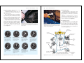
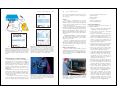
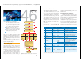
Figure 46-41. When connecting an analyzer to a vehicle, keep
all cables away from hot or moving parts. Test cables are very
expensive to replace.
Tech Tip!
With a coil pack, you must test each coil’s
output voltage separately. Just because one coil
passed its tests does not mean the others will.
By using the coil pack firing order and the secondary pattern, you can tell which coil should
be tested.
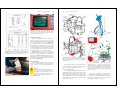
With the spark plug wire removed, a tall firing line
should stand out from the others. Look over to the scope
scale on the side of the screen. Read the voltage even
with the top of the spike. This value should equal the
capacity of the ignition coil.
Caution!
A few electronic ignitions may be damaged by
disconnecting spark plug wires while the engine
is running. Be sure to check manufacturer’s
directions.
With older electronic ignitions, coil output voltage
should range between 30,000–45,000 volts. However,
some electronic ignition coils are able to produce up to
100,000 volts.
Warning!
Even though ignition coil or coil pack current is
too low to normally cause electrocution, the
high voltage could injure you or cause a potentially deadly heart attack.
If the ignition coil voltage is below specifications, do
not condemn the coil until completing further tests. Low
coil output could be due to low primary supply voltage,
leaking secondary wires, or similar problems. Eliminate
these as sources of the problem before replacing the
ignition coil.
A load test, or acceleration test, measures the spark
plug firing voltages when engine speed is rapidly
increased. When an engine is accelerated, higher voltage
is needed to fire the spark plugs. While a defective component may produce a normal scope pattern at idle, it
may not operate properly under load.
To perform a load test, set the scope on parade and
idle the engine between 1000 and 1200 rpm. While
watching the firing lines on the scope, quickly open the
injection throttle valve (or carburetor throttle plate) and
release it. The firing voltage should increase, but it must
not exceed certain limits.
The highest firing line should not be more than 75%
of actual coil output. Typically, voltage should not exceed
15 kV in a contact point ignition or 20 kV in an electronic
ignition. The upward movement of the firing lines during
the load test should be the same. If any of the firing lines
are high or low, a defect is present.
Right bank
Front
A
Left bank
Cylinder power balance
Push buttons
1st
2nd
3rd
1
8
4
4th
5th
6th
7th
3
6
5
7
Engine firing order
8th Cancel
2
Cylinder Balance Test
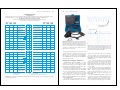
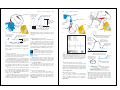
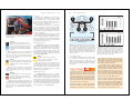
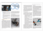
A cylinder balance test, also called a power balance
test, measures the power output from each of the engine’s
cylinders. As each cylinder is shorted, the tachometer
should indicate an rpm drop. During a cylinder balance
test, all cylinders should have the same percentage of rpm
drop (within 5%). If a shorted cylinder does not produce
an adequate amount of rpm drop, the cylinder is not firing
properly. Study Figure 46-42.
Caution!
Never short a cylinder in a vehicle with a
catalytic converter for more than 15 seconds;
converter damage could result.
If the rpm drop in one or more cylinders is below
normal, a problem common to those cylinders is indicated. The cylinders could have low compression (burned
valve, blown head gasket, or worn piston rings), a lean
mixture (vacuum leak, faulty fuel injector, or computer
malfunction), or other problems.
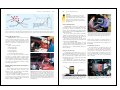
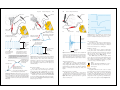
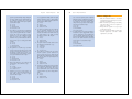
Cranking Balance Test
A cranking balance test is done to check the
engine’s mechanical condition. It can be used to isolate a
cylinder with low compression due to a burned valve,
worn piston rings, or other problems. The analyzer will
show how much current is drawn by the starter motor as
each cylinder goes through its compression stroke. High
current draw means high compression stroke pressure.
Low current draw (low display line) means that cylinder
has low compression. Look at Figure 46-43.
Figure 46-42. A cylinder balance test is done by pressing buttons on analyzer control panel. Each button will short and disable one cylinder. If the engine rpm does not drop sufficiently,
that cylinder is not producing enough power. Note how each
button corresponds to the firing order. A cylinder balance test
will find any engine cylinder that is not producing power. Some
analyzers will short each cylinder automatically and keep a
record of the results.
B
Figure 46-43. Cranking balance tests are used to check general engine compression. If any cylinder does not load the
starter motor as much as the others, it has low compression
pressure and a possible leak. A—All bar graphs are at the
same height, so all cylinders have same compression. B—The
number 5 cylinder has a low bar graph indicating less compression pressure. (Snap-on Tool Corp.)
Other Analyzer Tests
An analyzer is usually capable of performing other
tests besides those discussed in this chapter. These
include starter cranking amps, charging voltage, and
exhaust gas analysis. Such tests are almost identical to
those done with the individual instruments explained in
other chapters.
Duff's Garage
Problem: Mr. Farnsworth brings his 1999 Sierra
pickup truck into the shop with an elusive problem.
When asked to describe the problem, he says that the
engine runs fine but loses all power after about an
hour of highway driving. After the vehicle sits for about
20 minutes, it starts and runs again. Mr. Farnsworth
says he has taken his truck to four different shops and
none have been able to fix the problem.
Diagnosis: Duff checks for trouble codes and finds
none. He also checks for obvious problems but finds
nothing. Since the vehicle must be driven for an hour
before engine stops running, Duff suspects that
engine heat may be related to the problem, especially
since the ECM is located in the engine compartment
on this vehicle. He passes the job along to one of the
shop’s master automobile technicians.
The technician decides to begin his diagnosis by
heating the ECM to normal operating temperature to
determine whether it is causing the problem. He starts
the engine and lets it idle. To ensure that he does not
damage the ECM by overheating it, he places the
probe of a digital thermometer on the ECM case. Next,
he uses a heat gun to warm the ECM. When the ECM
reaches 200° F, the engine stalls. The technician
attempts to restart the vehicle without success.
Repair: The technician installs a new ECU and takes
the car for a test drive. The vehicle operates properly.
Back at the shop, the technician checks the ECM temperature with the digital thermometer. The ECM temperature is 210° F and the car is functioning normally.
The test drive and diagnostic time are added to customer’s bill and the car is released to the owner.