1
Chapter 46
Advanced Diagnostics
863
864
Section 8
Engine Performance
ECM TERMINAL VOLTAGE
5.0L (V.I.N. H)
This ECM voltage chart is for use with a digital voltmeter to further aid in diagnosis. These voltages were derived from a known
good car. The voltages you get may vary due to low battery charge or other reasons, but they should be very close.
The following conditions must be met before testing:
• Engine at operating temperature • Closed loop • Engine idling (for “engine run” column)
• Test terminal not grounded • Scanner not installed
Voltage Voltage Voltage
Voltage Voltage Voltage
Key
Engine Circuit
Key
Engine Circuit
“On”
Run
Open
“On”
Run
Open
Baro sensor signal
decreases with altitude
4.75
4.75
*.5
2
TPS sensor signal
*1.0
†5.0
*1.0
5.0
*2.5
*2.5
5.0
0
0
0
Sensor return
22
1
5
5
5
5V reference
21
.5–.65
12
12
*.5
**10
3–5
4-7
(var.)
5-10
(var.)
*.5
**11
20
3
Coolant temp. sensor
signal
*.5
Vacuum sensor
output
PWM EGR
solenoid
19
4
Air control solenoid
12.5
*1.0
*.5
*.5
M/C solenoid
18
5
Diagnostic test term
5
5
5
12
3rd
Gear switch
17
6
12
14
*.5
VSS signal
16
7
A/C W.O.T.
cutout (5.7L)
Coolant temp. sensor
return
0
0
0
Not used
15
8
Not used
*.5
10
*.5
*.5
1.7
Oxygen sensor–LO
14
9
Oxygen sensor–HI
.3–.45
*.5
*.5
*1.0
Dist. ref. pulse–LO
13
10
Dist. ref. pulse–HI
*.5
.1–.9
(var.)
1–2
(var.)
*.5
1–2
(var.)
*.5
EST
12
11
IGN. module bypass
*.5
3.7
Not used
J
K
Not used
*.5 P/N
12 D/R
*.5 P/N
14 D/R
12
Park/neutral switch
H
L
ESC (5.0L)
10
*.5
*.5
“Check engine” lamp
G
M
Not used
Not used
F
N
Throttle
kicker
E
P
Not used
D
R
4th gear switch
if used
Trans converter
clutch solenoid
Trouble code memory
power
*.5
IGN 1 power
C
S
Not used
*.5
Air switching
solenoid
B
T
Not used
Ground (to engine)
A
U
Ground (to engine)
12
12
12
0
*1.0
14
14
0
*.5
0
* = Value shown or less than that value
† = Wide open throttle
(var.) = variable
.3–.45
*.5
*.5
7-10
7-10
*.5
*.5
*.5
12
12
14
*.5
12
14
*.5
0
0
0
P/N = Park or Neutral
D/R = Drive or Reverse
** = If less than 1V rotate drive wheel to verify
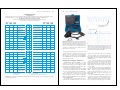
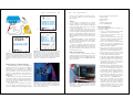
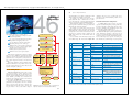
Figure 46-8. The service manual will usually specify the electrical values that should be present at each terminal of the computer
connector. (General Motors)
Noise from defective
alternator diode
A
Alternator diode noise
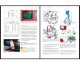
Figure 46-9. A breakout box is usually the last tool used to find
performance problems. It is connected to the wiring harness in
computer system. Then a multimeter can be used to check terminals on the breakout box for actual operating voltages, resistance, and current values. They can be compared to known
good values or to datastream values to find the cause of the
problem. (OTC Div. of SPX Corp.)
are compared to the manufacturer’s specifications. If the
measured values are not within specifications, you usually have a defective component or a wiring problem.
For example, if a reference voltage out of the ECM is
low, the ECM is bad or the wiring between the ECM and
the breakout box is faulty.
Isolating Electromagnetic Interference
Electromagnetic interference (EMI), or radiation
interference, occurs when an induced voltage enters
another system’s wiring. Sources of EMI can include
loose, misrouted, or unshielded spark plug wires; police
and CB radios; and aftermarket accessories.
In the past, electromagnetic interference was limited
to noise in the radio speakers. In late-model vehicles, EMI
can cause a computer-controlled system to malfunction.
For example, induced voltage from a loose spark
plug wire could enter a sensor wire. This unwanted
voltage would then enter the computer as false data.
Numerous computer malfunctions or false outputs could
result. See Figure 46-10.
To isolate the source of electromagnetic interference,
try turning off or disabling circuits or devices. If, for
B
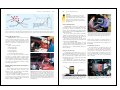
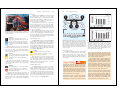
Figure 46-10. A—Electromagnetic interference can come from
a variety of sources and can cause major problems. This waveform is caused by a defective alternator diode. B—This is the
injector pulse waveform from the same vehicle. Note the hump
pattern similar to the alternator pattern. (IATN)
example, removing the drive belt from the alternator
corrects the problem, suspect problems inside the alternator. If the problem only occurs with the heated windshield turned on, check components within the heated
windshield circuit.
You can use a small transistor radio to find induced
voltage sources. Turn the radio on and set it on the AM
band, but do not tune it to a station. If the shop is
equipped with fluorescent lights, turn them off or test the
vehicle outside, away from power lines and any other
sources of EMI.
Move the radio around the engine compartment and
under the dash with the engine running. If EMI noise
(static) is present, a popping or cracking noise will be
produced by the transistor radio. You can also use a car
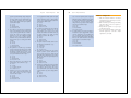
antenna cable and the car radio as a “noise sniffer.” See
Figure 46-11.
To correct an EMI problem, you must stop the source
of the interference (replace leaking spark plug wire, use
suppressing condenser, etc.) or shield the affected
system’s wiring from the interference (reroute the sensor
wire or wrap the wire with foil-type tape, for example).