1
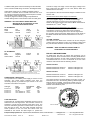
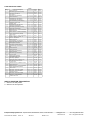
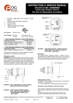
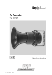
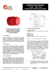
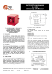
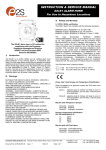
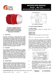
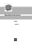
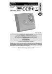
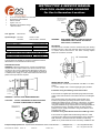
INSTRUCTION & SERVICE MANUAL E2xS121UL ALARM HORN SOUNDERS For Use In Hazardous Locations 45 Tones 3 stage Alarm Horn Sounder Automatic Synchronisation Volume control Type 4 / 4X / 13 Operating Temperature Range -20ºC to +55ºC E2xS121UL AC Sounder Tone Switch and Volume Control Positions Tone Selection DIP Switch N N E E L L S3 S2 C 7KA1 Unit Type No. Volume Control Potentiometer E2xS121UL Input Voltages: DC Units AC Units 10-30V or 48V 120V or 230V 50/60Hz Max. Operating Temperature / Code at +55ºC Ambient Hazardous Location Temperature Code Class I, Division 2, Groups A, B, C, D T3C (160ºC) Class II, Division 2, Groups F and G T6 (85ºC) Class III, Divisions 1 and 2 T6 (85ºC) Max. Operating Temperature / Code at +40ºC Ambient Hazardous Location Temperature Code Class I, Division 2, Groups A, B, C, D T4 (135ºC) WARNING - EXPLOSION HAZARD - SUBSTITUTION OF COMPONENTS MAY IMPAIR SUITABILITY FOR CLASS I, II DIVISION 2. MOUNTING The E2xS121UL sounder must be mounted using the rotating bracket as shown. If the cover has been removed to set the tone or volume control ensure that it has been correctly replace before the sounder is mounted. 18° Increments The equipment is suitable for use in the hazardous locations listed above or non-hazardous locations only. PRE-INSTALLATION WARNING - Before the E2xS121UL sounder is installed the required tone and output volume must be set. Note the units are factory set to tone 2 (800/1000Hz alternating at 2Hz) and maximum output. If necessary the unit should be connected to a suitable power supply in a safe area to determine what tone pattern and output level is required. Release nut to rotate bracket. WIRING INSTALLATION The E2xS121UL sounder is provided with 2 off M20 x 1.5 cable entries. 1 x ½” NPT adaptor and 1 x M20 stopping plug are provided. M4 Hex Socket Screw Installation using Field Wiring Leads and Conduit Spring Washer Flat Washer WARNING – DO NOT OPEN WHEN ENERGISED CAUTION - DO NOT OPEN WHEN AN EXPLOSIVE GAS OR DUST ATMOSPHERE IS PRESENT - - + S3 S3 S2 S2 Tone Selection DIP Switch + G G E2xS121UL DC Sounder Tone Switch and Volume Control Positions Volume Control Potentiometer If the sounder is supplied pre-wired with flying leads, these are colour coded and should be connected as shown in the diagram below. The conduit running from the supply to the sounder must include an equipment grounding conductor that is at earth potential to facilitate ground connection of the device. A number of sounders can be connected in a chain to the same supply using field installed wiring compartments that are appropriate for the hazardous location, provided that the conductor at earth potential can be readily connected to the ground lead on each sounder in the chain. Installation using Cable Glands without Field Wiring Leads If the sounder is supplied without field wiring leads, the cable connections are made into the terminal blocks on the electronic PCB assembly. Terminal blocks are suitable for field wiring (AWG 18-12). Strain relief has to be ensured by installation with __________________________________________________________________________________________________________________ European Safety Systems Ltd. Impress House, Mansell Road, Acton, London W3 7QH [email protected] Tel: +44 (0)20 8743 8880 www.e2s.com Fax: +44 (0)20 8740 4200 Document No. IS4202 Issue: H 26-03-13 Sheet 1 of 3 a suitable cable gland. Follow the markings for the terminals on the PCB and install wiring as shown in the diagram below. Cable glands need to be UL certified to ANSI/UL 2225 or C22.2 NO. 174-M1984. and to UL514B / CSA-C22.2 No. 18.312, ratings for hazardous locations must be equal to or better than the rating of the sounder used. If a high IP (Ingress Protection) rating is required then a suitable sealing washer must be fitted under the cable gland. WARNING - ALL ELECTRICAL WIRING MUST BE INSTALLED IN ACCORDANCE TO THE NATIONAL ELECTRICAL CODE AC SOUNDERS Black Live White Neutral Green/Yellow Ground L N C S2 S3 Violet Orange Yellow L N C S2 S3 C S2 S3 L N The operation of the second and third stages is different for DC and AC units. DC Units Second and Third Stage Tone Selection To activate the second stage, remotely switch the S2 orange wire to the negative supply. To activate the third stage, remotely switch the S3 orange wire to the negative supply. NOTE the DC power supply to the Red and Black wires must be maintained for 2nd and 3rd stages. AC Units Second and Third Stage Tone Selection To select the second and third stages on the E2xS121UL AC sounders the Common (C) Violet wire must be remotely connected to the S2 orange wire for the second stage and to the S3 yellow wire for third stage. NOTE the AC power supply to nd rd the Black and White lead must be maintained for 2 and 3 stages. C S2 S3 VOLUME CONTROL The volume on the E2xS121UL sounder can be set using the volume control (see figures 2 and 3). For maximum output level the potentiometer should be set to the fully clockwise position. L N Stage 2 C sounder on stage one simply connect the supply voltage to the flying leads (Red and Black for DC units, Black, White and Green/Yellow for AC units). Stage 3 NOTE if the second and third stage wires are not used they must be individually insulated to ensure that cannot make contact to any other wires. DC SOUNDERS Red Positive Black Negative Green/Yellow Ground + - S2 S3 Orange Yellow + - S2 S3 S2 S3 + - WARNING – HIGH VOLUME MAY CAUSE HARM TO PERSONNEL IN CLOSE PROXIMITY END OF LINE MONITORING On E2xS121UL DC units, dc reverse line monitoring can be used if required. All DC sounders have a blocking diode fitted in their supply input lines. An end of line monitoring resistor can be connected across the +ve and –ve terminals. If an end of line resistor is used it must have the following values:- S2 S3 24V DC Sounders + - Minimum Resistance 3k9 ohms Minimum Resistance 1k ohms Stage 2 Minimum wattage 0.5W Minimum wattage 2.0W Stage 3 NOTE if the second and third stage wires are not used they must be individually insulated to ensure that cannot make contact to any other wires. 48V DC Sounders Minimum Resistance 15k ohms Minimum Resistance 3k9 ohms Unit Type Max. I/P Volts 30V 58V 253V 132V E2xS121UL DC Sounder End of Line Resistor S3 S3 S2 S2 - - + E2xS121UL E2xS121UL E2xS121UL E2xS121UL Input Input @ 1kHz Voltage Current 24V DC 280mA 48V DC 215mA 230V 50/60Hz AC 76mA 120V 50/60Hz AC 142mA The resistor must be connected directly across the +ve and –ve terminals as shown in the following drawing. Whilst keeping its leads as short as possible, a spacing of at least 1/16 inch (1.58mm) must be provided through air and over surfaces between uninsulated live parts. + G G POWER SUPPLY SELECTION It is important that a suitable power supply is used to run the sounders. The power supply selected must have the necessary capacity to provide the input current to all of the sounders connected to the system. Minimum wattage 0.5W Minimum wattage 2.0W TONE SELECTION The E2xS121UL sounders have 45 different tones that can be selected for the first stage alarm. The sounders can then be switched to sound second and third stage alarm tones. The tones are selected by operation of a DIP switch on the pcb for both DC and AC units. The tone table opposite shows the switch positions for the 45 tones and which tones are available for the second and third stages. To operate the End of Line Resistor __________________________________________________________________________________________________________________ European Safety Systems Ltd. Impress House, Mansell Road, Acton, London W3 7QH [email protected] Tel: +44 (0)20 8743 8880 www.e2s.com Fax: +44 (0)20 8740 4200 Document No. IS4202 Issue: H 26-03-13 Sheet 2 of 3 TONE SELECTION TABLE Stage 1 Frequency Description 1 2 340Hz Continuous 800/1000Hz @ 0.25 sec Alternating 3 500/1200Hz @ 0.3Hz sec Slow Whoop 4 5 6 7 8 9 10 11 12 13 14 15 16 17 18 19 20 21 22 23 24 25 26 27 28 29 30 31 32 33 Switch 1 2 3 4 5 6 0 0 0 0 0 0 1 0 0 0 0 0 Stage 2 Stage 3 Tone 2 Tone 17 Tone 5 Tone 5 0 1 0 0 0 0 Tone 2 Tone 5 2400Hz Continuous 2400/2900Hz @ 7Hz Sweeping 2400/2900Hz @ 1Hz Sweeping 500/1200/500Hz @ 0.3Hz Sweeping 1 0 1 0 1 0 0 0 0 0 Tone 6 Tone 3 Tone 7 Tone 10 Tone 2 Tone 5 Tone 20 Tone 5 Tone 5 Tone 5 1200/500Hz @ 1Hz - DIN PFEER P.T.A.P. 2400/2900Hz @ 2Hz Alternating 1000Hz @ 1Hz Intermittent 800/1000Hz @ 0.875Hz Alternating 2400Hz @ 1Hz Intermittent 800Hz 0.25 sec on, 1 sec off Intermittent 800Hz Continuous 660Hz 150mS on, 150mS off Intermittent 0 0 0 1 0 0 Tone 15 Tone 2 1 0 1 0 1 0 1 Tone 7 Tone 2 Tone 4 Tone 15 Tone 4 Tone 2 Tone 18 Tone 5 Tone 5 Tone 5 Tone 5 Tone 5 Tone 5 Tone 5 Tone 2 Tone 27 800/1000Hz @ 1Hz Sweeping 1 0 0 1 1 0 1 1 0 0 1 1 0 1 1 1 1 0 0 0 1 1 1 1 0 0 0 0 0 1 1 1 1 1 1 1 0 0 0 0 0 0 0 0 0 0 0 0 0 0 0 0 0 0 0 544Hz (100mS)/440 Hz (400m/S) 0 0 0 0 1 0 - NF S 32-001 660Hz 1.8 sec on, 1.8 sec off Intermittent 1 0 0 0 1 0 1.4KHz - 1.6KHz 1s, 1.6KHz - 1.4 KHz 0.5s - NFC48-265 660Hz Continuous 554Hz/440Hz @ 1Hz Alternating 544Hz @ 0.875 sec Intermittent 800Hz @ 2Hz Intermittent 800/1000Hz @ 50Hz Sweeping 2400/2900Hz @ 50Hz Sweeping Bell 554Hz Continuous 440Hz Continuous 800/1000Hz @ 7Hz Sweeping 300Hz Continuous 660/1200Hz @ 1Hz Sweeping Two tone chime 745Hz @ 1Hz Intermittent Tone 2 Tone 5 0 1 0 0 1 0 Tone 2 Tone 5 1 0 1 0 1 0 1 0 1 0 1 0 1 0 Tone 2 Tone 2 Tone 2 Tone 6 Tone 29 Tone 29 Tone 2 Tone 26 Tone 2 Tone 7 Tone 2 Tone 26 Tone 26 Tone 2 Tone 5 Tone 5 Tone 5 Tone 5 Tone 5 Tone 5 Tone 15 Tone 5 Tone 5 Tone 5 Tone 5 Tone 5 Tone 15 Tone 5 Tone 45 1 0 0 1 1 0 0 1 1 0 0 1 1 0 0 1 1 1 1 0 0 0 0 1 1 1 1 0 0 0 0 0 0 1 1 1 1 1 1 1 1 0 1 1 1 1 1 1 1 1 1 1 1 1 1 0 0 0 0 0 0 0 0 0 0 0 0 0 0 1 34 1000 & 2000Hz @ 0.5 sec Aletrnating - Signapore 1 0 0 0 0 1 Tone 38 35 420Hz @ 0.625 Sec Australian Alert 0 1 0 0 0 1 Tone 36 Tone 5 36 500-1200Hz 3.75 sec /0.25 sec Australian Evac. 1 1 0 0 0 1 Tone 35 Tone 5 37 38 39 1000Hz Continuous - PFEER Toxic Gas 2000Hz Continuous 800Hz 0.25 sec on, 1 sec off Intermittent 0 0 1 0 0 1 1 0 1 0 0 1 0 1 1 0 0 1 Tone 9 Tone 34 Tone 23 Tone 45 Tone 45 Tone 17 40 544Hz (100mS)/440Hz (400mS) - NF S 32-001 1 1 1 0 0 1 Tone 31 Tone 27 41 42 43 44 Motor Siren - slow rise to 1200Hz Motor Siren - slow rise to 800Hz 1200Hz Continuous Motor Siren - slow rise to 2400Hz 0 1 0 1 1 1 1 1 Tone 2 Tone 2 Tone 2 Tone 2 Tone 5 Tone 5 Tone 5 Tone 5 45 1KHz 1s on, 1s off Intermittent - PFEER Gen. Alarm 0 0 1 1 0 1 Tone 38 Tone 34 0 0 1 1 0 0 0 0 1 1 1 1 0 0 0 0 SWITCH POSITION EXPLANATION 1 = Switch in the ON position. 0 = Switch in the OFF position.. __________________________________________________________________________________________________________________ European Safety Systems Ltd. Impress House, Mansell Road, Acton, London W3 7QH [email protected] Tel: +44 (0)20 8743 8880 www.e2s.com Fax: +44 (0)20 8740 4200 Document No. IS4202 Issue: H 26-03-13 Sheet 3 of 3 INSTRUCTION & SERVICE MANUAL E2xS121UL ALARM HORN SOUNDERS For Use In Hazardous Locations 1) Introduction The E2xS121 is an ATEX, IECEx and UL certified Sounder which produces a loud warning signal in a hazardous area. 45 first stage alarm sounds can be selected by internal switches and each one can be externally changed to a second and third stage alarm sound. The alarm horn may be used for Gas applications in Zone 2 as well as for Dust applications in Zone 22. 2) Having a temperature classification (for Gas applications) of: T1 T2 T3 T4 450ºC 300ºC 200ºC 135ºC May be used with Dust types: Group IIIA combustible flyings Group IIIB non-conductive dust Group IIIC conductive dust Warnings POTENTIAL ELECTROSTATIC CHARGING HAZARD – CLEAN ONLY WITH A DAMP CLOTH DO NOT OPEN WHEN AN EXPLOSIVE ATMOSPHERE IS PRESENT. Maximum Surface Temperature for Dust Applications: 3) 3.5 Ambient Temperature Range: Ratings and Markings ATEX/IECEx 85ºC -20ºC to +55ºC The E2xS121 Sounder complies with the following standards: EN60079-0:2012 / IEC60079-0 ed.6.0 (2011-06) EN60079-15:2010 / IEC60079-15 ed 4.0 (2010-01) EN60079-31:2009 / IEC60079-31 ed2.0 (2013-11) The Type Examination Certificate DEMKO 06ATEX0421554X / IECEx ULD 14.0012X has been issued by UL. This confirms compliance with the European ATEX Directive 94/9/EC for Group II, Category 3G/D equipment. The alarm horn carries the Community Mark and subject to local codes of practice, may be installed in any of the EEA member countries. This instruction sheet describes installations which conform to the current issue of EN60079-14/IEC60079-14 Electrical Installation in Hazardous Areas; EN60079-10-1 / IEC 6007910-1 Explosive Atmospheres - Classification of Areas. Explosive Gas Atmospheres; EN60079-10-2 / IEC 60079-10-2 Explosive Atmospheres - Classification of Areas. Explosive Dust Atmospheres. When designing systems for installation, the local Code of Practice should be consulted. The E2XS121 Sounder is rated as follows: II 3G II 3D Ex nA IIC T4 Gc Tamb -20°C to 55°C Ex tc IIIC 85°C Dc Tamb -20°C to 55°C 3.6 Ingress Protection Ratings The product is rated for ingress Protection as follows: IP rating per EN60529: IP66 To maintain the ingress protection rating, the two cable entries must be fitted with suitably rated, certified cable entry and/or blanking devices during installation. 3.7 Electrical Ratings Model No. E2xS121UL 24DC E2xS121UL 48DC E2xS121UL 115AC E2xS121UL 230AC CE Marking 4) Zones, Gas / Dust Groups and Temperature Classification When connected to an approved system the E2xS121 alarm horn may be installed in: Zone 2 Zone 22 explosive gas air mixture not likely to occur in normal operation, and if it does, it will only exist for a short time. explosive dust air mixture not likely to occur in normal operation, and if it does, it will only exist for a short time. May be used with gases in groups: Group IIA Group IIB Group IIC propane ethylene hydrogen / acetylene Nominal Voltage 24Vdc Voltage Range 10-30Vdc Current draw 48Vdc 38-58Vdc 215mA 115Vac 115Vac +/10% 50/60Hz 230Vac +/10% 50/60Hz 142mA 230Vac 280mA 76mA Special Conditions for Safe Use Special Condition for safe Use as stated on the Type Examination Certificate DEMKO 06ATEX0421554X / CoC IECEx ULD 14.0012X 4.1 Installation The product must only be installed by suitably qualified personnel in accordance with the latest issues of the relevant standards. The installation of the units must also be in accordance with any local codes that may apply and should only be carried out by a competent electrical engineer who has the necessary training. The Enclosure is non-conducting and may generate an ignition-capable level of electrostatic charges under certain __________________________________________________________________________________________________________________ European Safety Systems Ltd. Impress House, Mansell Road, Acton, London W3 7QH [email protected] Tel: +44 (0)20 8743 8880 www.e2s.com Fax: +44 (0)20 8740 4200 Document No. IS4202-ATEX Issue: A 19-03-15 Sheet 1 of 2 extreme conditions. The user should ensure that the equipment is not installed in a location where it may be subjected to external conditions (such as high-pressure steam) which may cause a built-up of electrostatic charges on non-conducting surfaces. The equipment has not been assessed as a safety-related device (as referred to by Directive 94/9/EC Annex II, clause 1.5). To maintain the ingress protection rating and mode of protection, the cable entries must be fitted with suitably rated ATEX / IECEx certified cable glands and/or suitably rated ATEX / IECEx certified blanking devices during installation according to EN / IEC60079-14. If a high IP (Ingress Protection) rating is required then a suitable sealing washer must be fitted under the cable gland. For use in explosive gas atmospheres, a minimum ingress protection rating of IP54 must be maintained. For use in explosive dust atmospheres, a minimum ingress protection rating of IP64 must be maintained. The enclosure is accessed by removing the 4 M4 Hex cover bolts fastening the enclosure. Do not open other joints of the enclosure for installation, service and maintenance. Connections are to be made into the terminal blocks using solid wire, sizes 0.5-4mm2 or stranded wire, sizes 0.5-2.5 mm2. Wire insulation needs to be stripped 8mm. Stranded wires may be fitted securely with crimped ferrules. Terminal screws need to be tightened down with a tightening torque of 0.45 Nm. Earthing connections should be made to the Internal Earth terminal on the PCBA. The internal earth bonding wire connects the PCBA earth terminal to the internal earth terminal in the enclosure. Check that the earth bonding wire between the two enclosure parts is secure and the ‘O’ ring seal is in place before closing. 4.2 Maintenance, Repair and Overhaul Maintenance, repair and overhaul of the equipment should only be carried out by suitably qualified personnel in accordance with the current relevant standards: EN60079-19 / IEC60079-19 Explosive atmospheres Equipment repair, overhaul and reclamation EN 60079-17/ IEC60079-17 Explosive atmospheres Electrical installations inspection and maintenance Units must not be opened while an explosive atmosphere is present. If opening the unit during maintenance operations a clean environment must be maintained and any dust layer removed prior to opening the unit. Electrostatic charging hazard - Clean only with a damp cloth __________________________________________________________________________________________________________________ European Safety Systems Ltd. Impress House, Mansell Road, Acton, London W3 7QH [email protected] Tel: +44 (0)20 8743 8880 www.e2s.com Fax: +44 (0)20 8740 4200 Document No. IS4202-ATEX Issue: A 19-03-15 Sheet 2 of 2 Manufacturer: EU Declaration of Conformity European Safety Systems Ltd. Impress House, Mansell Road, Acton London, W3 7QH, United Kingdom Equipment Type: E2xS112UL, E2xS121UL E2xB05UL, E2xB10UL E2xCS1125UL E2xL15UL, E2xL25UL Directive 94/9/EC: Electrical and Mechanical equipment for use in explosive atmospheres (ATEX) Notified Body for Type Examination: UL International Demko A/S Notified Body No.: 0539 Borupvang 5A, 2750 Ballerup, Denmark Type Examination Certificate: DEMKO 06 ATEX 0421554X Notified Body for Quality Assurance Notification: Sira Certification Service Notified Body No.: 0518 Rake Lane, Eccleston, Chester CH4 9JN, UK Quality Assurance Notification: SIRA 05 ATEX M342 Provisions fulfilled by the equipment: Ex na IIC T4/T3/T2 Gc (Ta -20ºC to +55ºC) Ex tc IIIC T85°C/100°C Dc (Ta -20ºC to +55ºC) Standards applied: EN60079-0:2012 + A11:2013 EN60079-15:2010 EN60079-31:2014 Directive 2014/30/EU: Electromagnetic Compatibility Directive (EMC) Standards applied: EN 61000-6-1:2007 EN 61000-6-2:2005 EN 61000-6-3:2007 / A1:2011 / AC: 2012 EN 61000-6-4:2007 / A1: 2011 Directive 2011/65/EU: RoHS Directive The product and all the components contained within it are in accordance with the restriction of the use of hazardous substances in electrical and electronic equipment. On behalf of European Safety Systems Ltd., I declare that, on the date the equipment accompanied by this declaration is placed on the market, the equipment conforms with all technical and regulatory requirements of the above listed directives. This Declaration is issued under the sole responsibility of the manufacturer. Martin Streetz Quality Assurance Manager Document No.: Date and Place of Issue: E2S Telephone: +44 (0)20 8743 8880 Fax: +44 (0)20 8740 4200 Email: [email protected] www.e2s.com DC-062_Issue_A London, 02/03/2015 QAF_252_Issue_2