1
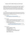
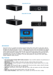
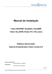
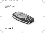
DINOSCORE TECHNICAL RESOURCE MANUAL
DINOSCORE
FIVE STAR REDEMPTION
8835 SHIRLEY AVENUE
NORTHRIDGE, CA 91324
Page 1 of 15
DINOSCORE TECHNICAL RESOURCE MANUAL
Table of Contents
1.
Table of Contents........................................................................................................ 2
INSTALLATION ................................................................................................... 3
THEME CONFIGURATION CHART ...................................................................... 9
TO INSTALL THE GUN: ........................................................................................ 10
TO UNDO THE GUN: ............................................................................................. 11
PARTS LIST FOR GUN .......................................................................................... 13
Page 2 of 15
DINOSCORE TECHNICAL RESOURCE MANUAL
1. INSTALLATION
1.1 FACTORY INSTALLED: If this version software was installed in the controller
as received from the factory, skip to section 2; PROGRAMMING.
1.2 UPGRADE: If your unit is being upgraded with this version of software, please
read the following instructions carefully.
Record all vend values, target values, and counters on a piece of paper. These
values will be lost when the new IC is installed and replaced with the factory
default information (see 1.3 below) . Previous values must be reentered, if different.
Turn off power and replace the CPU IC as shown by the instructions included with
the IC. Make certain the IC is oriented correctly with the dimple on the IC aligned
toward the JP10 connector. Failure to do so will destroy the IC. Be sure to cautious
of static discharge that could damage the IC or the controller.
Follow the instructions below to understand the new features and re-enter the
Vend and target values.
1.3 FACTORY DEFAULTS: This software is equipped with a table of values that will
be loaded into the vend value and target values locations. All counters will
initialize.
MODE
001
002
003
004
005
006
007
008
009
010
011
012
013
014
015
016
017
018
019
VALUE
0
1
150
30
4000
6000
2000
500
500
500
500
1000
1000
500
1500
500
50
DESCRIPTION
COINS FLIPPED
VENDS OUT
N/A
ATTRACT TIME ON
ATTRACT TIME OFF
THEME DELAY TIME
VEND 1
VEND 2
VEND 3
VEND 4
VEND 5
VEND 6
VEND 7
VEND 8
VEND 9
VEND 10
VEND 11
VEND 12
VEND 13
Page 3 of 15
DINOSCORE TECHNICAL RESOURCE MANUAL
020
021
022
023
024
025
026
027
028
029
030
031
032
033
034
035
036
037
038
039
100
75
0
SEE
PAGE 10
VEND 14
VEND 15
VEND 16
TARGET 1 POINTS
TARGET 2 “
TARGET 3 “
TARGET 4 “
TARGET 5 “
TARGET 6 “
TARGET 7 “
TARGET 8 “
TARGET 9 “
TARGET 10 “
TARGET 11 “
TARGET 12 “
TARGET 13 “
TARGET 14 “
TARGET 15 “
TARGET 16 “
2. PROGRAMMING
2.1 OVERVIEW: The Din score is easily programmed using the four buttons marked
MODE, RESET, UP, DN (DOWN). To enter the program mode press the MODE
button. The mode number will be shown on the left three digits of the display. The
value for each mode is shown on the right five digits. Each press of the button will
advance the programming to the next mode. On modes 004 through 039, the UP
and DN buttons are used to increment or decrement the setting. The UP & DN
buttons may be pressed intermittently to increment or decrement one at time, or the
may be held and will change slowly at first, then very quickly. When the numbers
are changing quickly, remove your finger when near the desired number, and then
press again to change slowly. Both UP & DN may be pressed simultaneously to
clear these settings to zero.
Pressing RESET will halt programming at any step and save whatever changes
have been made.
2.2 MODE 191; AVERAGE POINTS PER COIN: This is the first mode to appear after
MODE is pressed. The Average Points per Coin is calculated by the controller and
is used to determine the amount of average score earned from each coin over time.
The number may be reset to zero by pressing the UP & DN buttons simultaneously.
The Average Points per Coin is determined by the total number of points scored,
divided by the number of coins entered into the machine. Press the MODE button to
advance to the next mode, or press RESET to return to the game.
Page 4 of 15
DINOSCORE TECHNICAL RESOURCE MANUAL
2.3 MODE 192; TARGET TEST: This mode is used to check the operation of each of
the sixteen target groups. The right five digits of the display will be blank if no
targets are on. The vertical side bar segments of the right four digits are used to
indicate the function of the target. See the following figure to find the display
location for each of the sixteen target groups. When a quarter (or other opaque
object) interrupts the sensor on the target, the corresponding segment will light. If a
segment is lighted when no object is in the sensor, it indicates a problem with the
target sensor or its associated wiring. Press MODE or RESET to exit this mode.
MODE #
16
13
15
14
12
11
9
8
5
4
1
10
7
6
3
2
Target Test
2.4 MODE 193; VEND BUTTON TEST: This test is similar to the target test above.
Each of the vend buttons on the keypad and bulk venders may be tested. The
associated bar on the display will light while the button is pressed. See chart below.
Press MODE or RESET to exit this mode.
MODE #
16
13
15
14
12
11
9
8
5
4
1
10
7
6
3
2
Vend Button Test Locations
2.5 MODE 194;FREE VEND TEST: When this mode is entered a score of 99,999 will
be entered on the right side of the display. Each of the venders may be cycled by
pressing its associated button. The indicator light or led associated with the vendor
will light and stay lighted until the next vendor is selected or the mode is exited.
Page 5 of 15
DINOSCORE TECHNICAL RESOURCE MANUAL
The 99,999 score will decremented by the value programmed for that vend. Press
MODE or RESET to exit this mode.
2.6 MODE 001; COINS FLIPPED COUNTER: This non-resettable counter will
accumulate the total of the number of coins exiting the gun. The maximum count is
99,999 after which the counters will rollover to zero and begin again. Press MODE
or RESET to exit this mode.
2.7 MODE 002; VENDS OUT COUNTER: This non-resettable counter indicates the
total number of vends cycles (without regard to points) that have occurred,
including bulk dispensers. The maximum count is 99,999 after which the counters
will rollover to zero and begin again. Press MODE or RESET to exit this mode.
2.8 MODE 003:
2.9 MODE 004; ATTRACT ON: The number of seconds that the attract relay is
energized. The attract relay may be used to turn on attract devices when the game is
in attract mode (dancing zeros on display ). Pressing the UP & DN buttons
simultaneously may zero the value. Press MODE or RESET to exit this mode.
2.10
MODE 005; ATTRACT OFF: The number of seconds the attract relay is off,
once it has been on.
2.11
MODE 006; THEME DELAY: The number of seconds the theme operates
after a coin leaves the gun. Scoring may take place only during the theme delay
period. If no points are present after the theme delay, the game will return to the
attract mode. The theme delay relay is energized during the period. Pressing the UP
& DN buttons simultaneously may zero the value. Press MODE or RESET to exit
this mode.
2.12
MODES 007-022; VEND VALUES: The number of points required to vend a
price for each vender. As each vend mode is selected, the corresponding LED on
the vender will light to help identify the prize being programmed.
Note:
These modes are ignored when a ticket or token dispenser is installed. Pressing the
UP & DN buttons simultaneously may zero the value. Press MODE or RESET to
exit these modes.
2.13
MODES 023 – 038; TARGET POINT VALUES: The number of points
awarded for each of the sixteen target groups. Mode 023 corresponds to target
group 1, Mode 024 corresponds to target group 2, etc. When a ticket or token
dispenser is installed, these values determine the number of tickets or tokens
dispensed. Pressing the UP & DN buttons simultaneously may zero the value. Press
MODE or RESET to exit these modes.
2.14
MODE 039; CONSOLATION POINTS: The number of points awarded as a
consolation prize. A consolation is earned if after a coin-out, no score is earned.
Page 6 of 15
DINOSCORE TECHNICAL RESOURCE MANUAL
Depending on the setting of the dipswitches, consolation points may be awarded. 1)
Always; or only when the score equals zero.2) at the end of the Theme Delay; or
when an optional coin verification switch is fitted. See section on dipswitch setting
below. If no consolation is desired, set this value to zero.
3. DIPSWITCH SETTING
3.1 DIPSWITCH, GENERAL INFORMATION: The dipswitch (SW1) is located on
the main board near the programming buttons. The Off position is toward the edge
of the PC board. The dipswitch is only “read” during a power – up cycle. To change
the dipswitch settings; turn off the power, change the switches and reapply power.
3.2 DIPSWITCH 1; ATTRACT AUDIO: When this switch is in the OFF position, the
theme music and other sounds will be played during the attract on time.
3.3 DIPSWITCH 2; NOT USED.
3.4 DIPSWITCH 3; NOT USED.
3.5 DIPSWITCH 4; Speed of Ticket/tokens dispensed. Off = fast
3.6 DIPSWITCH 5; CONSOLATION PRIZE DECISION: If dipswitch 5 is in the
OFF position, consolation points will be awarded whenever a coin is flipped, but
no targets are hit, regardless of score displayed. When the switch is in the ON
position, consolation points are added only when no targets are hit and the score is
zero. There must be points programmed into MODE 39 and either dipswitch 6 or 7
OFF, for consolation to be awarded.
3.7 DIPSWITCH 6; COIN VERIFY SWITCH: If the optional coin verifies switch has
been installed to the coin box, moves this switch to the OFF position. When this
switch is OFF. The consolation points (if any) will be added immediately.
3.8 DIPSWITCH 7; CONSOLATION ON TIME-OUT: Consolation points will be
added at the end of the Theme Time if this switch is in off position. If dipswitch 6
were OFF, this switch would normally be turned ON. If dipswitch 6 and 7 are ON
no consolation will be awarded.
3.9 DIPSWITCH 8; TICKET / TOKEN DISPENSER: When in the OFF position this
switch enables the dispenser. One ticket or token will be dispensed for each point
shown on the display.
Page 7 of 15
DINOSCORE TECHNICAL RESOURCE MANUAL
DINOSCORE THEME CONFIGURATION
VOLCANO
VOLCANO
VOLCANO
20
25
10
19
21
20
HEAD
HORN
HEAD
NO HORN
300
500
22
FACE
FACE
10
10
24
HORNS
25
200
26
FACE
15
VOLCANO
VOLCANO
28
25
10
27
29
5
10
9
7
1
5
50
1
8
3
6
10
11
5
12
4
20
10
25
13
3
5
2
1
14
1
1
3
Page 8 of 15
DINOSCORE TECHNICAL RESOURCE MANUAL
THEME CONFIGURATION CHART
MODE NUMBER
23
24
25
26
27
28
29
30
31
32
33
34
35
36
37
38
39
40
TARGET VALUE
1
1
1
3
5
10
10
15
20
25
25
50
200
300
500
1
1
TARGETS
6
14
2,9
1,10
5,8,13
7,11,20
24,25,29
28
3,19
12,21
27
4
26
22
23
GROUP NUMBER
1
2
3
4
5
6
7
8
9
10
11
12
13
14
15
16
CONSOLATION POINT
Number of tickets or
tokens dispensed
Page 9 of 15
DINOSCORE TECHNICAL RESOURCE MANUAL
TO INSTALL THE GUN
A.
B.
C.
D.
E.
Install the sensor (3) on front of gun.
Slide in gun, screw in the shoulder bolt on side of turret.
Doing this make sure gun moves up/down with case.
Screw in two wheels (6).
Screw in Phillips screw: holding up the gun harness.
Page 10 of 15
DINOSCORE TECHNICAL RESOURCE MANUAL
TO UNDO THE GUN
A.
B.
C.
D.
E.
Undo the Philips screw holding the harness to gun body.
Undo the set-screw (2) on side of turret.
Undo wheels (6).
Gun assembly should slide out now.
Take out the GUN SENSOR (3) by undoing the Philips screw (4) underneath.
Do not lose the plastic washer on top (5).
F. Peel off any sticker on gun and save them for the new gun.
Page 11 of 15
DINOSCORE TECHNICAL RESOURCE MANUAL
TRIGGER GUN ASSEMBLY
Page 12 of 15
DINOSCORE TECHNICAL RESOURCE MANUAL
PARTS LIST FOR GUN
DESCRIPTION PARTS
PART
NUMBER
GUN STOP
GUN BACK END
GUN TRIGGER ROD HOLDER
GUN TRIGGER LINKAGE HOLDER
GUN COIN LIP
GUN TILT BACK STOP
GUN TRIGGER RETAINER
GUN INSERTION SHIM
GUN INSERTION SHIM THIN
GUN COVER PLATE
GUN TURRET PLATE
TURRET PIVOT SCREW
PLUNGER BRACKET
GUN RE-INFORCEMENT TURRET
GUN BODY
.867 X .079 TOKEN
HUNGARIAN 20 F
TAIWAN 10 NT
900 X .05 TOKEN
GERMAN MARK
ARGENTINA
(1.125)
1.062 X .068 TOKEN
GUN BOTTOM COVER
GUN PIVOT COVER
GUN HAMMER W/2 PIN
GUN HAMMER WITH PIN
GUN TRIGGER
GUN HAMMER BEARING
GUN HANDLE
GUN COCKING SHAFT
GUN COCKING PIN
GUN LEVER LEFT
GUN LEVER RIGHT
GUN TRIGGER WIRE
GUN COCKING WIRE
GUN PIVOT SCREW
GUN COCKING LEVER SPRING
GUN TRIGGER SPRING
GU2-0009
GU2-0010
GU2-0011
GU2-0012
GU2-0013
GU2-0014
GU2-0015
GU2-0016
GU2-0016-2
GU2-0017
GU2-0018
GU2-0023
GU2-0024
GU2-0025
GU3-0001
COMMENTS
GU3-0002-1K
GU3-0002-F
GU3-0002-G
GU3-0002-H
GU3-0002-N
GU3-0002-L
GU3-0002-R
GU3-0002-S
GU3-0003
GU3-0004
GU3-0005
GU3-0006
GU3-0007
GU3-0008
GU3-0012-A
GU3-0013
GU3-0014
GU3-0016
GU3-0017
GU3-0018
GU3-0019
GU3-0023
GU3-0026
GU3-0027
Page 13 of 15
DINOSCORE TECHNICAL RESOURCE MANUAL
GUN PAW SPRING
GUN HAMMER SPRING
BRASS SPACER
SPACER .193 ID X .250 OD, 19
SPACER .125 ID X .360 OD, 470
SPACER .128 ID X .187 OD , 43
LEVER BEARING
PIN, TYPE D, GROOVED, 188X
DOWEL PIN
GUN WEIGHT
COIN CHUTE END BLOCK
COIN CHUTE (SINGLE HOLE)
PIVOT STOP
TURRET MOUNT
TURRET PIN / PHILLIPS
PLUNGER HAMMER
BALL SHOOTER
LARGE PLUNGER SPRING
SMALL PLUNGER SPRING
PLUNGER SLEEVE
RUBBER TIP FOR SHOOTER
BRONZ BUSHING BEARING
TURRET MOUNT SCREW PLUNGER
5/8” BRASS TURRET BUSHING
OLD BRASS TURRET SCREW BUSHING
NYLON SPACER
HAMMER STOP
TURRET PIN SCREW (4-40X3/8)
PIVOT COVER SCREW (4-40X1/4)
BOTTOM PIVOT COVER SCREW PLU NGER (2)
GUN COIN LIP (2) (2-56X1/2”)
TOKEN SLIDE SCREWS (4) (2-56X1/2”)
GUN BOTTOM COVER SCREW (6)
ROD HOLDER SCREW (4-40X1/4”)
GUN HANDLE SCREW (4) (4-40X3/8”)
GUN SENSOR SCREW
BOTTOM PIVOT COVER SCREW TRIGGER (2)
GUN LEVER SCREW (2) (5-40X1/2”)
GUN WEIGHT SCREW (2) (1/4-28X1”)
PLUNGER BRACKET SCREW (2) (8-32X1/2”)
GUN COCKING SHAFT WASHER (2) T/G
PLUNGER BRACKET WASHER (2)
WASHER FOR HAMMER STOP
E-CLIP 3/8”
RUBBER BUMPERS
GU3-0028
GU3-0029-A
GU3-0036
GU3-0037
GU3-0039
GU3-0040
GU3-0050
GU3-0058
GU3-0060
GU3-0061
GU3-0062
GU3-0064
GU3-0065
GU3-0069
GU3-0070
GU3-0071
GU3-0072
GU3-0073
GU3-0074
GU3-0075
GU3-0076
GU3-0077
GU3-0077-1
GU3-0078
GU3-0079
GU5-0039
GU9-0022
HH1-0106
HH1-1104-A
HH1-1104-A
HH1-3004
HH1-3008
HH1-3104
HH1-3104
HH1-3106
HH1-3106
HH1-3106
HH1-3208
HH1-3708
HH1-9408-B
HH4-0001
HH4-0013
HH4-0018
HH5-0023
HH9-0001
Page 14 of 15
DINOSCORE TECHNICAL RESOURCE MANUAL
TURRET BLUE
TURRET BROWN
TURRET YELLOW
NEW TRIGGER GUN (W/O SLIDE)
NEW PLUNGER GUN (W/O SLIDE)
TRIGGER PLUNGER GUN
TOKEN SLIDES
QUARTER
QUARTER & .984
QUARTER & .900
.882
.900
.984
1”
.879 TOKEN
100 JAPAN YEN
ALLADIN’S CASTLE
NICKEL
.864X .109 TOKEN
GUN HARNESS
2 GUN AMPLIFIER P.C B.D
GUN COUNTER PCB
GUN SENSOR BOARD
GUN-COCKING LEVER REBUILD KIT
GUN SPRING REBUILD KIT
HAMMER REBUILD KIT
PAWL REBUILD KIT
PLUNGER REBUILD KIT
TRIGGER REBUILD KIT
GUN SCREW KIT
MA2-0005-B
MA2-0005-BR
MA2-0005-Y
MA2-0006-T
MA2-0006-P
MA2-0006-RT
MA2-0007-SIZE
MA2-0007-A
MA2-0007-AU
MA2-0007-AC
MA2-0007-B
MA2-0007-C
MA2-0007-D
MA2-0007-E
MA2-0007-IE
MA2-0007-J
MA2-0007-K
MA2-0007-X
MA2-0007-Y
MA2-0022-2
PC1-1025-4
PC1-1050-1
PC1-2011-4
SK1-CLA
SK1-GSK
SK1-HA
SK1-PA
SK1-SP
SK1-TA
SK1-SK
Page 15 of 15