1
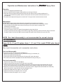
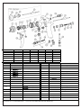
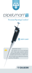
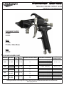
Panther Series
TEFLON COATED SPRAY GUN
PRODUCT INFORMATION
Corrosion Control
P100H
P200C
Glue
P100G
P100G - Water Base
Zinc
P200Z
AIR CAP AND FLUID NOZZLE CHART
MODEL NO.
P100H
AIR CAPS
21-1095T
P100G
P100G
Waterbased
21-2266T
21-2266-3T
21-1590-08
21-1590-18
Air Cap
Ring
Fan
Control
*SUGGESTED GUN INLET PRESS.
AVAILABLE FLUID NOZZLES
NEEDLES /
marking on needle
21-1001
60-1502
50
31-0214
31-0215
31-0216
31-0217
Included
60-1500
45
31-0618 1.8mm (.070")
40-1115 (115)
Included
60-1500
45
31-1593-08 0.8mm (.022")
31-1593-18 1.8mm (.070")
32-0618 1.8mm (.070")
32-0622 2.2mm (.086")
32-0628 2.8mm (.110")
32-2118Z 1.8mm (.070")
32-2122Z 2.2mm (.086")
32-2128Z 2.8mm (.110")
40-1508
40-1518
40-1218 (218)
40-1222 (222)
40-1228 (228)
40-1218 (218)
40-1222 (222)
40-1228 (228)
P200C
22-2064T
22-2062T
Included 60-1500
50
50
P200Z
22-2062T
22-2064T
Included 60-1500
50
50
1.4mm (.055")
1.5mm (.059")
1.6mm (.063")
1.7mm (.070")
40-1100 (100)
Coating Atomization Technologies P.O. Box 17820, Boulder CO 80308 (888) 820-4498 Fax (303) 438-5708
www.sprayCAT.com
Operation and Maintenance Instructions for
Panther
Spray Guns
Operation
1. Connect air supply hose at handle of gun.
2. Connect a pressurized fluid supply or paint siphon cup to the gun fluid inlet.
3. Fluid flow can be controlled using the fluid control knob, this restricts flow by limiting needle travel. It
is best to control fluid flow by proper selection of fluid orifice size and use the fluid control knob to “fine
tune flow rate”.
4. Fan width can be adjusted using the fan control knob. Turning the knob clockwise narrows the fan.
Maintenance
IMPORTANT! Routine cleaning and maintenance is essential to insure proper gun operation.
Several states prohibit spraying solvent into the atmosphere and require the use of covered gun cleaner.
1. If a gun cleaner is being used, connect and clean the gun in the gun cleaner according to the
manufactures instructions.
2. If a gun cleaner is not being used:
For pressure setups, remove air cap and clean separately using clean solvent.
Connect a pressurized solvent supply to the fluid inlet, trigger the gun allowing solvent to flow thru the gun until clean.
For siphon setups, first clean the siphon cup thoroughly then spray clean solvent thru the gun until clean.
NOTE: Gun head disassembly is not recommended for normal cleaning
and maintenance.
Items 29, 30, 31 and 32 replace items 1, 2, 3 and 13 for model P100G water based
setup.
Gun head disassembly and reassembly instructions:
Gun head disassembly
To remove the nozzle carrier (5) and air cap adapter (6):
1. Remove the air cap (1), fluid nozzle tip (2), fluid nozzle body (3), and needle (13)
2. Remove the needle seal cartridge (23)
3. Loosen the locknut (9) and remove fluid inlet (10) using a 5/8” open-end wrench
4. The nozzle carrier and air cap adapter will now slide forward from the gun body (11).
Gun head reassembly
1. Install a new o-ring (7) on the air cap adapter.
2. Install the thread locknut (9) onto the fluid inlet as far as possible.
3. Slide the nozzle carrier (5) into air cap adapter (6) and insert into the gun body as far as possible. Be sure the
nozzle carrier extends into the hole at the back of the gun head. Install the needle seal (23) but do not tighten.
4. Rotate the nozzle carrier until the fluid inlet port in the nozzle carrier is aligned with the threaded hole in the body.
While in this position, insert the fluid inlet (10) and tighten firmly.
5. Tighten the needle seal (23) to approx. 12 ft.-lb. torque.
6. Tighten the fluid inlet (10) to approx. 25 ft.-lb. torque.
7. Tighten the locknut (9) to approx. 33 ft.-lb. torque.
*
*
*
*
*
*
PANTHER MODEL
ITEM 3
ITEM 4
ITEM 5
ITEM 6
ITEM 23
Repair Kit
P100H
31-1201
Not Used
60-L11H
60-12H
60-1400
10-110
P100G
31-2201
61-1005
60-L11C
60-12C
60-1400
10-110
P100G - WB
See Air Cap Chart
Not Used
60-L11C
60-12C
60-1400
10-106
P200C
32-2201
98-8020
60-L21C
60-22
60-1400
10-106
P200Z
See Air Cap Chart
98-8020
60-L21C
60-22
60-1402
10-108
ITEM NO.
PART NO.
DESCRIPTION
*
*
*
ITEM NO.
PART NO.
DESCRIPTION
1
See Air Cap Chart
Air Cap
17
60-201
Rear Bushing
2
See Air Cap Chart
Fluid Nozzle Tip
18
60-119
Seal*
3
See Pa nth er Model Fluid Nozzle Body
19
60-1520
Air Valve Assembly
4
See Pa nth er Model Gasket*
20
60-302**
Air Valve Poppet
5
See Pa nth er Model Nozzle Carrier
21
60-125
O-Ring*
6
See Pa nth er Model Air Cap Adapter
22
61-1003
Air Valve Spring*
7
60-131
O-Ring*
23
See Pa nth er Model Needle Seal Cartridge
8
60-124
Fluid Inlet Seal
24
60-2101
9
60-128
Locknut
10
60-126
Fluid Inlet Fitting
60-1125
Trigger
25
60-1510
Air Control
25A
60-122
Plug (optional)
Panther Gun body CONV.
26
60-104
Air Inlet Fitting
60-1116
Panther Gun body HVLP
27
60-1033
Trigger Pivot Set
12
See Air Cap Chart
Fan Control Assembly
28
98-109
Allen Plug
13
See Air Cap Chart
Fluid Needle
29
21-1592
Housing
14
60-202
Fluid Control Knob
30
21-1591
Sw irl Insert
15
60-209
Spring Seat*
31
See Air Cap Chart
Nozzle
16
60-206
Needle Return Spring*
32
See Air Cap Chart
Needle
11
*Indicates part included in repari kit # 10-108 & 10-110
Note: Items 29, 30, 31, 32 and replace items 1, 2, 3, and 13 for the model P100G 1590 w ater based setup
Revised 1/18/13