1
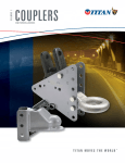
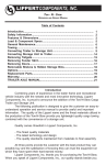
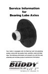
WILBURY AXLE Operational Service Manual TABLE OF CONTENTS Safety Notice 2 Brakes 2-3 Electric Brake Maintenance 4 Trailer Connection Brake Troubleshooting 5 6-7 Electrical 7-8 Hubs, Drums and Bearings E-Z Lube 9-11 11 Suspension Systems Tire and Wheel Safety 12-13 14-15 Replacement Parts 16 Limited Warranty 17 Texas Pride Trailers The Best Built, Best Backed, Best Priced Trailers - GUARANTEED Website: www.texaspridetrailers.com 1241 I-45 | Madisonville, TX 77864 | Phone: 936-348-7552 | Fax: 936-348-7554 WILBURY AXLE Operational Service Manual Safety Notice Page 2 SAFETY NOTICE Providing safe dependable operation of your axle(s) and related components is important. (Proper service and repair procedures are essential for safe, reliable operation of the axle and personal safety of its operator.) This manual provides basic procedures for service and repair using established industry standards. There are many variations in procedures to repair and maintain the axle and its related parts; however, it is not possible to provide you with all the details for various service procedures. Refer to your trailer manufacturer's owners manual for any specific warnings and procedures that may relate to the safety and maintenance of your trailer. If these procedures are not clear to you or if you are unsure, you should contact a trailer repair facility who has a trained axle repair technician for advice or repair. NEW AXLE SETUP AND ADJUSTMENTS Wheels Re-torque wheel nuts as instructed by the torque requirements on new trailers at 25, and 50 miles. See page 16 for torque rates. Adjust between 200 and 300 miles after all brake components have seated; recheck at 3,000 miles. See tire manufacturer's recommendations. Brakes Tire Pressure Brake Controller Settings Refer to Brake Controller manufacturers recommendations Texas Pride Trailers The Best Built, Best Backed, Best Priced Trailers - GUARANTEED Website: www.texaspridetrailers.com 1241 I-45 | Madisonville, TX 77864 | Phone: 936-348-7552 | Fax: 936-348-7554 WILBURY AXLE Operational Service Manual Brakes Page 3 BRAKES Your trailer’s electric brakes are actuated by an electromagnet which is energized and modified by an electrical impulse from the brake controller. The trailer brakes will apply smoothly and slightly ahead of the truck brakes if all the brake components are installed and connected properly. The brakes are actuated with the electrical impulse from the controller to the electromagnets which, when in contact with the armature plate (surface of the drums) will move the actuating levers which will apply the pressure to the primary shoe and will engage the secondary shoe much like hydraulic brakes on a passenger vehicle. As brake pressure (applied by the driver) is increased, the electrical flow to the magnets increases the pressure between the brake shoes and drums to meet the braking requirements of the driver. Electric brakes have been used on a variety of trailers for many years and offer many benefits to the driver. Please refer to the brake controller information provided by the installer of your towing vehicle for procedure and operation of the controller. DOUBLE CHECK! Make sure your controller is installed according to the manufacturer’s recommendations. Make sure that the proper brake controller adjustments have been made to correctly engage the tow vehicle brakes and the trailer brakes to work together to provide safe and comfortable braking. Make sure that the brakes have been properly seated by applying the brakes repeatedly and lightly for about 20 to 30 times with a 20 m.p.h. decrease in speed, e.g. 35 m.p.h. to 15 m.p.h. to begin the "seating in" of the brake to the brake drum components. Do this in a safe and low traffic area for everyone's safety. Below is a view of the 10" and 12" brakes used on your trailers axle(s), depending on your trailer and manufacturer's specifications. Left Hand 10" Electric Brake Left Hand 12" Electric Brake Texas Pride Trailers The Best Built, Best Backed, Best Priced Trailers - GUARANTEED Website: www.texaspridetrailers.com 1241 I-45 | Madisonville, TX 77864 | Phone: 936-348-7552 | Fax: 936-348-7554 WILBURY AXLE Operational Service Manual Electrical Brakes Maintenance Page 4 ELECTRIC BRAKE MAINTENANCE Your trailer brakes should be adjusted after the first 250 miles with all of the brake components having seated. Since driving conditions and areas vary you should re-check brakes adjustments at 3,000 mile intervals. CAUTION Do not place jack on axle or springs. Use jack stands to secure trailer. ADJUSTMENT PROCEDURE 1. 2. 3. 4. 5. 6. 7. Make sure your trailer is on a level surface and is free of any potentially dangerous items. Jack up the trailer and secure with jack stands. Make sure you are using the trailer manufacturer's procedure for jacking and safely supporting the trailer until the tire and wheel are clear of the ground surface. Find the adjusting hole cover and remove it from the backing plate. Use a brake adjusting tool to adjust the star wheel (of the adjuster) and expand the brakes until the brake shoes are sufficiently expanded so that the tire and wheel will not easily rotate. Now move the star wheel in the opposite direction until you can feel a little resistance from the brake and replace the hole cover. Carefully lower the tire to the ground. Repeat this procedure for all wheels making sure to adjust all brakes at the same time. Special note: 10K G.D. 12¼” x 3 3/8” and 12K G.D. 12¼” x 5” brakes are self-adjusting. All others require adjustment as stated above. Texas Pride Trailers The Best Built, Best Backed, Best Priced Trailers - GUARANTEED Website: www.texaspridetrailers.com 1241 I-45 | Madisonville, TX 77864 | Phone: 936-348-7552 | Fax: 936-348-7554 WILBURY AXLE Operational Service Manual Trailer Connection Page 5 Texas Pride Trailers The Best Built, Best Backed, Best Priced Trailers - GUARANTEED Website: www.texaspridetrailers.com 1241 I-45 | Madisonville, TX 77864 | Phone: 936-348-7552 | Fax: 936-348-7554 WILBURY AXLE Operational Service Manual Brake Troubleshooting Page 6 TROUBLESHOOTING GUIDE FOR ELECTRIC BRAKES Dragging Brakes Check for defective controller. Check for corroded brake assembly. Check for weak or broken brake shoe return (retractor) spring. Check for loose, worn, bent or broken brake components Check for improper controller installation. Check overadjustment Check for out-of-round brake drums Noisy Brakes Check underadjustment Check for worn brake shoes. Check for contaminated brake linings. Check for weak or broken brake shoe retractor springs. Check for bent backing plate. Check wheel bearing adjustment. Check for worn or damaged wheel bearings. Check for worn or damaged magnets. Check lubrication Inoperative Breakaway System Check for dead or weak 12-volt battery, on trailer. Check all wiring and connections. Check breakaway switch. If only one brake is operating, check other magnets. No Brakes Check for defective circuit breaker. Check for open or shorted circuit. Check for properly wired system including a good ground between towing vehicle and trailer. Check under-adjustment. Check for worn or defective magnet(s). Intermittent or Surging Brakes Check for a damaged or worn connector between towing vehicle/trailer. Check that controller is installed correctly and functioning correctly. Check for out-of-round and/or cracked brake drums. Check for properly wired system, including a good ground between towing vehicle and trailer Check for defective magnet or wiring. Check for loose/worn wheel bearings. Check for linings or magnet contaminated with grease or oil. Texas Pride Trailers The Best Built, Best Backed, Best Priced Trailers - GUARANTEED Website: www.texaspridetrailers.com 1241 I-45 | Madisonville, TX 77864 | Phone: 936-348-7552 | Fax: 936-348-7554 WILBURY AXLE Operational Service Manual Electrical Page 7 TROUBLESHOOTING GUIDE FOR ELECTRIC BRAKES Ineffective or Weak Brakes Ensure trailer is not overloaded. Check for loose or corroded connections. Check for properly wired system. Check for a shorted circuit. Check for worn or defective magnet. Check brake adjustment. Check for bent backing plate flange. Check for contaminated brake linings. Check brake system wiring. Check for worn, damaged brake linings. Check for weak or broken brake shoe retractor spring. Check for worn brake drums. Check that correct controller is installed. Check for improper controller installation. Grabbing or Locking Brakes Check for contaminated brake linings. Check for weak or broken brake shoe retractor spring. Check for rust on armature plate or brake drum. Check for faulty controller and/or improper controller installation. ELECTRICAL VOLTAGE MEASUREMENT PROCEDURE To measure voltage, connect the voltmeter to both magnet wire leads while the towing vehicle is connected and the engine is running to insure accurate readings. The voltage should begin at 0 and the controller is increased slowly to approximately 12 volts. If a controller does not produce this voltage control refer to your brake controller troubleshooting and information manual. The lower reading will provide smoother braking while the higher may produce sharp or severe braking. AMPERAGE MEASUREMENT PROCEDURE Amperage is the electrical current flowing in the brake system while the magnets are energized. Make sure of your ammeter's rating to prevent damage to the meter. An easy place to check the amperage is at the output wire from the brake controller to the brakes. Disconnect this (blue) wire and put the ammeter in series into this line. Please refer to the following chart. Texas Pride Trailers The Best Built, Best Backed, Best Priced Trailers - GUARANTEED Website: www.texaspridetrailers.com 1241 I-45 | Madisonville, TX 77864 | Phone: 936-348-7552 | Fax: 936-348-7554 WILBURY AXLE Operational Service Manual Electrical Page 8 Individual amperage draw can be measured at the magnet by inserting the ammeter in the line of the magnet you wish to check. Disconnect one of the wire leads from the wire magnet and attach the ammeter between the two wires. Reconnect the wires when completed. BRAKE SIZE AMPS TO MAGNET 2 BRAKES 4 BRAKES 6 BRAKES 7” x 1¼” 2.5 5.0 10.0 15.0 10” x 2¼” 3.0 6.0 12.0 18.0 12” x 2” 3.0 6.0 12.0 18.0 12¼” x 3 3/8” 3.0 6.0 12.0 18.0 12 ¼” x 5” 3.0 6.0 12.0 18.0 There are several possible reasons that may cause voltage variations. Listed below are the most probable. Poor electrical connections. Open circuits. Broken wires or incorrect wire size. Brake controller malfunction. Electrical problems can also be caused by bare wires, defective controllers or shorts in the magnet coil. Locating the source of a short circuit should be done by checking individual sections. Should you find the amperage reading drops to zero after disconnecting the trailer, then the short is in the trailer; if the amperage is high after all of the magnets are disconnected, the short is somewhere in the trailer wiring. Please note that the majority of electrical brake complaints can be traced to the controller. Refer to your brake controller manual to insure your controller is correctly adjusted and that the connections are in compliance with the manufacturer's specifications. Texas Pride Trailers The Best Built, Best Backed, Best Priced Trailers - GUARANTEED Website: www.texaspridetrailers.com 1241 I-45 | Madisonville, TX 77864 | Phone: 936-348-7552 | Fax: 936-348-7554 WILBURY AXLE Operational Service Manual Hubs, Drums and Bearings Page 9 HUBS, DRUMS AND BEARINGS WILBURY Trailer Products bearing configuration uses industry standards for bearing sets (bearings & cones) and hubs. This standard of using tapered roller bearings helps to reduce the axial end play provided at assembly and is essential to performance of the bearings life. The bearings are packed with lithium base grease. Your axles may be equipped with the WILBURY Trailer Products E-Z Lube system which provides for lubricating the hubs at a special grease fitting. This option allows grease to flow through specially machined axle spindles, which have been drilled to allow the grease to be passed from the fitting to the inner bearing and back out through the outer bearing. BRAKE DRUM INSPECTION The brake drum surface should be inspected for heavy scoring or excessive wear. If the wear is greater than .020” oversized, it should be resurfaced. If the drum has worn out of round by more than .015", it should be re-machined. If wear or scoring is more than .090" on the diameter, the drum will have to be replaced. When turning the drum surface, the maximum rebore diameter is as follows: z z z z 7” brake drum-7.090” diameter 10” brake drum-10.090” diameter 12” brake drum-12.090” diameter 12¼” brake drum-12.340” diameter The armature surface (which contacts the magnet) needs to be inspected for uneven wear or scoring. Drums can be resurfaced by removing no more than .030” and should be to 120 micro inch finish. In the event you need to turn the drums or resurface the armature it is recommended that you replace the magnets at the same time. Special notes: Make sure the inside of the hub cavity is carefully cleaned and free of any contamination following turning and before re-assembly (after resurfacing and before reinstalling). Texas Pride Trailers The Best Built, Best Backed, Best Priced Trailers - GUARANTEED Website: www.texaspridetrailers.com 1241 I-45 | Madisonville, TX 77864 | Phone: 936-348-7552 | Fax: 936-348-7554 WILBURY AXLE Operational Service Manual Hubs, Drums and Bearings Page 10 HUB INSPECTION, REMOVAL, REPLACEMENT AND ADJUSTMENTS A. Removal of Hub 1. 2. 3. 4. 5. 6. Remove wheel Remove grease cap Remove cotter pin or bend tang washer on E-Z Lube Unscrew the spindle nut counter clockwise Remove spindle washer Remove hub from spindle B. Seal Inspection and Replacement 1. 2. 3. Seals should be replaced each time the hub is removed. Pry the seal out of the hub with a screwdriver. Tap new seal into place. C. Bearing Maintenance, Adjustments, and Replacement 1. 2. 3. 4. 5. 6. Inspect for corrosion and wear. If any rust or wear exists on the bearing then remove and replace. If bearings are found to be in good condition, then cleaning and repacking the grease is all that is needed. Note: Do not spin bearings with compressed air. Hand pack each bearing individually using a premium lithium base wheel bearing grease. Reinstall the hub, reversing the procedure above using the bearing adjustment procedures below. If you have the E-Z Lube system, refer to the E-Z Lube Lubrication Procedure. D. Bearing Adjustment 1. Feel and Drag Method: Tighten slotted nut until hub drags slightly when rotated. (Rotating the hub while tightening the nut seats the bearing.) Loosen the slotted nut 1 /6 turn (1 hex) (1/3 turn (2 hexes)) to align nut slot with the cotter pin hole. Wheel should turn freely. Insert new cotter pin through nut and spindle. If necessary loosen, never tighten, nut to align slot with the hole in the spindle. Bend one leg of cotter pin over the end of the spindle and the other leg over the nut. Tap legs slightly to set. Cotter pin must be tight. If equipped with E-Z Lube, bend tang back into position. Texas Pride Trailers The Best Built, Best Backed, Best Priced Trailers - GUARANTEED Website: www.texaspridetrailers.com 1241 I-45 | Madisonville, TX 77864 | Phone: 936-348-7552 | Fax: 936-348-7554 WILBURY AXLE Operational Service Manual E-Z Lube Page 11 2. Torque Wrench Method: Make sure nut is loose. Tighten nut with torque wrench to cm (an) initial torque of 50 ft. lbs. Loosen nut from initial torque and finger tighten. Insert new cotter pin through nut and spindle. If equipped with E-Z Lube, reset tang. If necessary, loosen, never tighten, nut to align slot with the hole in the spindle. Bend one leg of cotter pin over the end of the spindle and the other leg over the nut. Top legs slightly to set. Cotter pin must be tight. Special Note: Bearing units should be inspected every year or 12,000 miles whichever comes first. E-Z LUBE LUBRICATION PROCEDURE 1. 2. 3. Remove the rubber cap at end of the grease cap. Using a standard grease gun place the tip onto the grease fitting at the end of the spindle. Pump the grease into the fitting as you continue pressure you will notice the old grease coming out at the cap. When you begin to see the new grease, remove the gun and clean off any excess and replace the rubber cap. Texas Pride Trailers The Best Built, Best Backed, Best Priced Trailers - GUARANTEED Website: www.texaspridetrailers.com 1241 I-45 | Madisonville, TX 77864 | Phone: 936-348-7552 | Fax: 936-348-7554 WILBURY AXLE Operational Service Manual Suspensions Page 12 WILBURY SUSPENSION SYSTEMS WILBURY also provides your suspension systems as well as the axle assemblies. These components are designed to perform a number of tasks to provide your trailer with the best and smoothest towing possible. The above drawings offer a view of single and tandem axle assemblies in both the double eyed and slipper spring versions. Your axle undercarriage may be equipped with double eye leaf springs or slipper leaf springs depending on the manufacturer's specification. Double eye leaf springs have eyes at both ends of the spring and have special bushings to protect them from wear. They do not need lubricating. Slipper leaf springs have an eye at only one end which is also fitted with a special bushing to protect them from wear. The trailing end of the spring is designed to slide against the rear hangers. Either of these suspensions will provide you with comfortable trouble free towing, but as with any mechanical parts, they should be inspected periodically depending on usage at recommended intervals of 6 months or 5,000 miles whichever comes first. Should you find excessive wear in the hanger components you should have them replaced by a qualified technician. Should you find excess wear, in any of the attaching parts bolts, nuts, bushings, broken or worn out springs, you should replace them and torque attaching bolts to the following standards as follows on page 13. Texas Pride Trailers The Best Built, Best Backed, Best Priced Trailers - GUARANTEED Website: www.texaspridetrailers.com 1241 I-45 | Madisonville, TX 77864 | Phone: 936-348-7552 | Fax: 936-348-7554 WILBURY AXLE Operational Service Manual Suspensions Page 13 CAUTION Make sure the trailer is raised and supported according to the manufacturers requirements before beginning any repairs of the trailer SUSPENSION TORQUE REQUIREMENTS U-Bolt 3/8" 7/16" 1/2" 9/16" Torque 30-50 ft. lbs. 45-70 ft. lbs. 45-70 ft. lbs. 60-85 ft. lbs. Shackle Bolt 7/16" Torque 30-50 ft. lbs. not torqued; snug fit to allow parts to move easily. The lock nut is used to position parts. 9/16" USE CAUTION If the above maintenance procedures are not applied, there could be serious damage to the components possibly resulting in physical injury and/or damage to property. To perform undercarriage modifications please carefully follow the recommendations as follows: 1. Raise and support the trailer until it is clear of the ground. 2. When the trailer is securely supported place a block under the axle close to the end which will be repaired. You need to secure only the axle tube in order to remove and replace the part you want to replace. If your trailer has two axles you will need to support both axle tubes. 3. Disassemble the attaching parts (u-bolts, nuts, and the links). 4. Remove the eye bolts and the springs and place them clear of your working area. 5. If needed remove the spring bushings and replace with new ones. 6. Use the reverse order to reinstall your components. Special note: The fittings that attach the springs to the chassis mounts are designed specially to be wear resistant and should not be lubricated. Texas Pride Trailers The Best Built, Best Backed, Best Priced Trailers - GUARANTEED Website: www.texaspridetrailers.com 1241 I-45 | Madisonville, TX 77864 | Phone: 936-348-7552 | Fax: 936-348-7554 WILBURY AXLE Operational Service Manual Wheel and Tire Safety Page 14 WHEEL AND TIRE SAFETY Your trailer manufacturer has specified the wheel and tires to be used. It is very important that you do not make any changes that may alter the recommended size or load capacities. Any deviations, however slight or unnoticeable, may cause damage or be dangerous to operate. TIGHTENING PROCEDURE 1. After mounting a wheel over the studs, start all lug nuts by hand to prevent cross threading. 2. After all the lug nuts have been snugged, tighten the nuts to the recommended torques using the sequence and progressive values provided on page 16. Re-torque after first 50 miles of use, and periodically re-check the torque. TORQUE REQUIREMENTS It is a necessary procedure to periodically check the torque levels of your wheel lug nuts. They must be maintained at the appropriate torque recommendations to prevent loose wheels, potentially broken studs and to prevent the wheel from separating from the axle. TIRE PRESSURE Tire pressure should be checked frequently, and inflated to the tire manufacturer's recommendations. CAUTION Wheel torque must be maintained to insure that damage is not incurred to the wheel, wheel studs and or attaching parts. Texas Pride Trailers The Best Built, Best Backed, Best Priced Trailers - GUARANTEED Website: www.texaspridetrailers.com 1241 I-45 | Madisonville, TX 77864 | Phone: 936-348-7552 | Fax: 936-348-7554 WILBURY AXLE Operational Service Manual Wheel and Tire Safety Page 15 REQUIRED WHEEL TORQUES (ft-lbs) 1st Setting 2nd Setting Final Setting 8-12-13" Wheel 20-25 35-40 50-75 14-15-16" Wheel 20-25 50-60 90-120 16" Wheel 9/16"studs 20-25 70-80 130-150 BOLT TIGHTENING SEQUENCE 5 Hole Pattern 6 Hole Pattern 8 Hole Pattern WARNING Modifications of the tire & wheel assembly can result in damage to the trailer or personal injury if not used according to the manufacturer's specifications. Texas Pride Trailers The Best Built, Best Backed, Best Priced Trailers - GUARANTEED Website: www.texaspridetrailers.com 1241 I-45 | Madisonville, TX 77864 | Phone: 936-348-7552 | Fax: 936-348-7554 WILBURY AXLE Operational Service Manual Replacement Parts Page 16 REPLACEMENT PARTS MAGNET REPLACEMENT KITS Brake Size Wire Color Brake Mtg. Nut Torque (ft-lbs) 10 x 2¼ Green 45-70 12 x 2 Black 25-50 12¼ x 3 3/8 Orange 55-80 BRAKE SHOE REPLACEMENT KITS Brake Size Single Kit (1 Brake) 10 x 2¼ K71-047-00 12 x 2 K71-127-00 12¼ x 3 3/8 Right Side 4739-3; Left Side 4739-4 K71-498-00 RH; K71-499-00 LH BEARING REPLACEMENT CUPS & CONES Brake Size Hub Cup Cone 10 x 2¼ 5 Bolt L-68111 Inner and L-44610 Outer L-68149 inner and L-44649 Outer 12 x 2 6 Bolt 25520 Inner and LM67010 Outer 25580 Inner and LM67048 Outer 12 x 2 8 Bolt 25520 Inner and 14276 Outer 25580 Inner and 14125A Outer 12¼ x 3 3/8 8 Bolt 382A Inner and 25520 Outer 387A Inner and 25580 Outer SEAL REPLACEMENT Brake Size Hub Seal 10 x 2 ¼ 5 Bolt 010-004-00 12 x 2 6 Bolt 010-054-00 12¼ x 3 3/8 8 Bolt K71-386-00 Texas Pride Trailers The Best Built, Best Backed, Best Priced Trailers - GUARANTEED Website: www.texaspridetrailers.com 1241 I-45 | Madisonville, TX 77864 | Phone: 936-348-7552 | Fax: 936-348-7554 WILBURY AXLE Operational Service Manual Limited Warranty Page 17 WILBURY TRAILER PRODUCTS LIMITED WARRANTY WILBURY Trailer Products - Axle Division extends to the original purchaser only, a limited warranty on each WILBURY Trailer Products tubular axle(s) against defects in material or workmanship for a period of two (2) years from date of purchase. WILBURY Trailer Products - Axle Division extends to the original purchaser only a limited warranty on each WILBURY Trailer Products Equalizer Torsion Axle(s) against defects in material or workmanship for a period of five (5) years from date of purchase. 1. To obtain warranty service, please call or send the following information to the address listed on the back. a. Name and mailing address of purchaser. b. Proof of date of purchase. c. Name of manufacturer of unit under which axle is mounted. d. Model, year and serial number of unit. e. Name and address of dealer from whom unit was purchased. 2. This warranty does not extend to: a. The connecting of brake wiring to the trailer wiring or trailer wiring to the towing vehicle wiring. b. The attachment of the axles to the frame. c. Hub imbalance, or any damage caused thereby. d. Parts not supplied by WILBURY Trailer Products - Axle Division. e. Any damage whatever if caused by or related to any alteration of the axle. f. Use of axle assembly on unit other that to which it was originally mounted. g. Normal wear including brake linings and magnets. 3. This warranty does not cover defects caused by: a. Improper installation. b. Damage (not resulting from defect or malfunction) while in the possession of the customer. c. Unreasonable use (including failure to provide reasonable and necessary maintenance.) 4. Repair or replacement under this warranty is the exclusive remedy for the customer, WILBURY Trailer Products - Axle Division shall not be liable for any incidental or consequential damages, including any towing fees, hotel bills, telephone calls and meals for breach of any express or implied warranty on the axles. Texas Pride Trailers The Best Built, Best Backed, Best Priced Trailers - GUARANTEED Website: www.texaspridetrailers.com 1241 I-45 | Madisonville, TX 77864 | Phone: 936-348-7552 | Fax: 936-348-7554