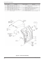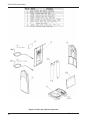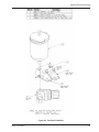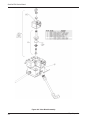
1
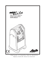
NewLife® Elite / NewLife® Oxygen Concentrator Service Manual 0459 AirSep Corporation • 401 Creekside Drive • Buffalo, NY 14228-2085 USA Telephone: (716) 691-0202 • 24-Hour Fax: (716) 691-4141 NewLife® Elite Service Manual Expedited Product Warranty Check service is always at your fingertips with AirSep: http://www.airsep.com/Support/Warranty_Information.aspx OR In the US or Canada, dial 866-873-9277 AirSep® is a registered trademark of AirSep Corporation. NewLife Elite and NewLife are registered trademarks of AirSep Corporation. ® MN105-1 ® AirSep® Corporation Rev. C 02/14 NewLife® Elite Service Manual Table of Contents Section 1.0 Introduction 1.1 Equipment Provider Responsibility 1-1 1.3 Functional Specifications 1-4 Section 2.0 Operation Check and Oxygen Concentration Test 1.2 Important Notice and Symbol Explanations 1-2 2.1 Description of Operation 2-1 2.3 Alarm System 2-2 2.2 Section 3.0 Patient Instructions 2.4 3.1 3.2 Operation Check 2.3.1 2.3.2 Section 4.0 Equipment Provider Maintenance Battery Test 2-2 Power Failure Alarm Test Oxygen Concentration Test and Specification General Instructions 3.2.2 2-2 2-3 3-1 Routine Maintenance by the Patient 3.2.1 2-1 3-1 Cleaning the Air Intake Gross Particle Filter Checking the Alarm System Battery 3-1 3-2 4.1 4.2 AirSep® Corporation Routine Maintenance 4-1 4.1.2 4-1 4.1.1 Air Intake Gross Particle Filter/GPF 4.1.3 Optional Filter Replacement 4.1.4 4.1.5 Product Filter Replacement Battery Replacement Recording Maintenance Cleaning and Infection Control 4.2.1 Preparing for New Patient Use 4-1 4-2 4-2 4-3 4-3 4-4 i – table of contents NewLife® Elite Service Manual Section 5.0 Service 5.1 Components 5.2 Cabinet Removal 5.2.1 Removing Side Panel(s) 5.2.3 Removing Lower Front Cover 5.2.2 5.2.4 5.2.5 5.2.6 Removing Back Panel Removing Control Panel Superstructure Caster Replacement 5.3 Compressor 5.3.1 Solenoid Valves 5.4 5.5 5.6 5.7 5.8 5.3.2 Compressor Replacement Capacitor Replacement 5.4.1 Feed or Waste Valve Rebuilding 5.4.3 Solenoid Valve Coil Replacement 5.4.2 Feed or Waste Valve Reassembly Sieve Bed Replacement 5.5.1 5.5.2 Sieve Bed Removal Sieve Bed Installation Cabinet Fan Replacement Circuit Board Replacement 5.7.1 5.7.2 Circuit Board Removal Circuit Board Installation Product Regulator Check and Setting 5.8.1 Setting Product Regulator for Normal Operation Back Pressure Correction at 5 lpm 5.8.2 5.8.3 5.8.4 Product Regulator Lockout Product Regulator Cleaning or Rebuilding 5.9 High or Low Pressure Switch Replacement (In Equipped Units) 5.10.1 5.10 Circuit Breaker Replacement Circuit Breaker Installation 5.11 ON/OFF Power Switch Replacement ii – table of contents 5.10.2 Circuit Breaker Removal 5.11.1 ON/OFF Power Switch Removal 5-1 5-1 5-1 5-1 5-1 5-1 5-1 5-2 5-2 5-3 5-4 5-4 5-4 5-5 5-5 5-6 5-6 5-7 5-7 5-8 5-8 5-9 5-10 5-10 5-10 5-11 5-12 5-13 5-14 5-14 5-14 5-14 5-14 AirSep® Corporation NewLife® Elite Service Manual 5.11.2 ON/OFF Power Switch Installation 5.12 Buzzer Replacement 5.14 Flowmeter Replacement 5.13 Hour Meter Replacement 5.14.1 5.14.2 Flowmeter Removal Flowmeter Installation 5.15 Power Cord Replacement 5-15 5-15 5-15 5-16 5-16 5-16 5-16 Section 6.0 Troubleshooting 6.1 Operating Pressure Test 6-1 6.1.1 High Operating Pressure 6-1 6.1.2 Low Operating Pressure 6-2 6.2 General Troubleshooting 6-2 6.3 Troubleshooting Chart 6-4 6.4 Tool Kit and Pressure Test Gauge 6-7 Appendix Exploded Drawings Figure 1: Control Panel Assembly Figure 2: Main Structure Assembly Figure 3: Base and Cabinet Components Figure 4: Test Block Assembly Figure 5: Valve Block Assembly Figure 6: Compressor Assembly Figure 7: Adsorption Bed Assembly A-1 A-2 A-3 A-4 A-5 A-6 A-7 AirSep® Corporation iii – table of contents NewLife® Elite Service Manual 1.0Introduction 1.1 Equipment Provider Responsibility All Equipment Providers of the NewLife Elite/NewLife® Oxygen Concentrator must assume responsibilities for handling, operational check-out, patient instruction, and maintenance. These responsibilities are outlined below and throughout this manual. ® WARNING NewLife units must not be used for or with any lifesupporting applications. Geriatric, pediatric, or any other patients unable to communicate discomfort while using this machine may require additional monitoring. Advise patients to immediately notify their Equipment Providers and/or physicians in case of an alarm or any discomfort. As an Equipment Provider, you must do all of the following: Inspect the condition of each NewLife unit immediately upon delivery to your business location. Note any sign of damage, external or internal, on the delivery receipt, and report it directly to both the freight company and AirSep Corporation immediately. Check the operation of each NewLife before delivery to a patient. Always operate the unit for a reasonable length of time and check that the oxygen concentration level is within specifications as referred to in Section 2.4. (Test the battery and power disconnect alarm as described in Section 2.3 of this manual.) Deliver NewLife units only to patients authorized by a physician’s prescription. The NewLife must not be used as a life-supporting device. A backup supply of oxygen must be available. Instruct patients how to use the NewLife in conjunction with the Patient Manual. Instruct patients to notify their physicians and/or Equipment Providers if they experience any signs of discomfort. Instruct each patient how to perform routine maintenance of the air intake gross particle filter and how to check the alarm system battery. (Refer to Section 3.2.) Be available to service each patient at any time. Maintain the NewLife in accordance with Section 4.0. Repair components and replace parts only as outlined in this manual. Use only AirSep parts for replacement in NewLife Oxygen Concentrators. AirSep® Corporation 1-1 NewLife® Elite Service Manual 1-2 1.2 Important Notice and Symbol Explanations As you read the manual, pay special attention to the WARNING, CAUTION, and NOTE messages. They identify safety guidelines or other important information as follows: WARNING: Describes a hazard or unsafe practice that can result in severe bodily injury or death. CAUTION: Describes a hazard or unsafe practice that can result in minor bodily injury or property damage. NOTE: Provides information important enough to emphasize or repeat. AirSep® Corporation NewLife® Elite Service Manual The following harmonized symbols (pictograms), used for nonEnglish language countries, will be located on the exterior of the NewLife unit: Read the Patient Instruction Manual. No smoking within five feet of this device, oxygencarrying tubing, or accessories. No open flames within five feet of this device, oxygencarrying tubing, or accessories. No oil, grease or petroleum-based products on or near the unit. Oxygen outlet Oxygen alarm Nebulizer option AirSep® Corporation 1-3 NewLife® Elite Service Manual 1.3 Functional Specifications Dimensions: 28.5 in. high, 15.7 in. wide, 14.5 in. deep (72.4 cm high, 40.0 cm wide, 36.8 cm deep) Weight: 54.0 lb; shipping weight - 59.0 lb (24.5 kg; shipping weight - 29.0 kg) Electrical Requirements: 120 VAC, 60 Hz, 4 amps, 350 watts 230 VAC, 50 Hz, 4 amps, 350 watts Capacity: 5 liters per minute at 90% oxygen (Based on 70°F [21°C] at sea level) Accuracy: Flowmeter ±5% full scale. (Based on precalibrated analysis.) Concentration: 1–3 liters per minute at 95% + 0.5/ - 3% 4 liters per minute at 92% + 3.5/ - 3% 5 liters per minute at 90% + 5.5/ - 3% Response Time: Allow 5 minutes to attain maximum oxygen concentration. Positioning: Operate the unit in an upright position, maintaining at least six inches of open space on all sides for ventilation. 0459 1-4 AirSep® Corporation NewLife® Elite Service Manual 2.0 Operation Check and Oxygen Concentration Test 2.1 Description of Operation Air enters the NewLife Oxygen Concentrator through an external air intake gross particulate filter. This filtered air enters the compressor via a suction resonator, which quiets the compressor’s suction sound. Pressurized air then exits the compressor and passes through a heat exchanger. The heat exchanger reduces the temperature of the compressed air. Next, a two-way solenoid feed valve directs the air into one of two sieve beds that contain molecular sieve. The unique property of molecular sieve enables it to physically attract (adsorb) nitrogen when air passes through this material, thus producing high concentration oxygen. There are two sieve beds: while one produces high concentration oxygen, the other is purged of the nitrogen it adsorbed (collected) while it made oxygen. Each adsorber produces oxygen for approximately eight seconds and delivers it to the product tank. Oxygen exits the product tank through a pressure regulator, product filter, flow control valve, flowmeter, and finally exits the unit. The flow control valve, which is part of the flowmeter, controls the amount of oxygen delivered to the patient. The NewLife unit delivers up to 95.5% pure oxygen at flow rates from 1–5 lpm. NOTE: NewLife Elite OxiSilent™ option incorporates an additional felt intake filter prior to air entering the compressor. 2.2 Operation Check AirSep tests every NewLife Oxygen Concentrator thoroughly after manufac ture. You must perform the following test to ensure that no damage occurred in shipping or handling. AirSep® Corporation 1 Open and inspect all cartons (that contain units) upon delivery. Unpack the unit and remove it from the carton. Inspect the unit itself for damage. If the exterior of a unit’s carton is damaged, or the unit itself is damaged, note it on the freight bill signed by the driver. 2 Plug in the power cord of the unit, and set the ON/OFF switch to the ON position. Check to see that the following occurs: a. A continuous alarm loudly sounds for approximately five seconds to indicate that the battery for the alarm is good. See the troubleshooting chart in Section 6.0 of this manual if the unit’s alarm does anything other than sound loudly for five seconds. b. The compressor runs. Listen for the sound. c. Exhaust air flows out of the bottom of the unit. 2-1 NewLife® Elite Service Manual d. OPTIONAL: The Oxygen Monitor’s amber light remains on until the oxygen concentration reaches 85% ± 3% (approximately two minutes). 3 Turn the flowmeter adjustment knob counterclockwise until it stops (wide open). The maximum flow should register 5.5 lpm (the 5.5 lpm line should appear to split the middle of the flowmeter ball) with no connections at the oxygen outlet. If not, refer to Section 5.8.1 to set the product regulator. 4 Perform an oxygen concentration test, as described in Section 2.4. 2.3 Alarm System The NewLife Oxygen Concentrator is equipped with a battery-powered alarm system, which sounds a continuous and loud alarm when a power failure occurs. It sounds an intermittent alarm if the high or low pressure indicators are activated or if the optional oxygen monitor detects lower than therapeutic levels of oxygen concentration. The alarm remains on until you correct the alarm condition or you set the ON/OFF switch to the OFF position. Refer to Section 6.0 for a list of probable alarm causes. 2.3.1 Battery Test Each time the NewLife unit is turned on, a five-second audible alarm sounds to indicate the condition of the battery. NOTE The audio alarm must sound loudly for approximately five seconds each time the unit is turned to ON to indicate the battery is in good condition. 2.3.2 Power Failure Alarm Test To test the power failure alarm, take the following step: Unplug the unit, and set the ON/ OFF switch to the ON position. 2-2 This should immediately activate the audio alarm. If it does not, refer to the troubleshooting chart in Section 6.0 of this manual. AirSep® Corporation NewLife® Elite Service Manual 2.4 Oxygen Concentration Test and Specification To ensure that the unit’s output of oxygen is within specification, you must perform a test of oxygen concentration. Test the unit upon delivery to a patient and at periodic intervals. Equipment Providers, based on their expertise and documentation, may establish and implement their own protocol to check oxygen concentration. The interval established may be longer or shorter than 90 days, which is AirSep’s default time period for providers who do not choose to establish their own protocol. 1 If an oxygen humidifier bottle is used, remove it from the oxygen outlet. 2 Connect a calibrated oxygen concentration analyzer to the oxygen outlet. 3 Verify that the product flow rate delivered by the unit matches the patient’s prescription and does not exceed the capacity of the unit. 4 Set the unit’s ON/OFF power switch to the ON position. (It takes approximately five minutes for the oxygen concentration to stabilize.) Take oxygen concentration readings every 60 seconds until the analyzer shows that two consecutive readings are the same. 5 Disconnect the oxygen analyzer, and reconnect the humidifier bottle (if used) and any other equipment/ accessories that may be required. 6 Adjust the flowmeter adjustment knob to the prescribed level. NOTE Do not measure oxygen concentration output after the product stream passes through a humidifier bottle, or erroneous readings will result. AirSep NewLife Oxygen Concentration Specifications AirSep® Corporation Liter Flow Specification In Spec 1–3 lpm 95% + 0.5/ - 3% 92% or higher 4 lpm 92% + 3.5/ - 3% 89% or higher 5 lpm 90% + 5.5/ - 3% 87% or higher 2-3 NewLife® Elite Service Manual 3.0 Patient Instructions 3.1 General Instructions It is important that patients thoroughly understand how to operate the AirSep NewLife unit. This enables proper treatment as prescribed by a qualified, licensed physician. You must explain that the purpose of this therapy is to alleviate symptoms. If patients experience any discomfort or the unit alarms, they must notify their Equipment Provider and/or physician immediately. You, as the Equipment Provider, are responsible to see that each patient receives the Patient Manual. Locate the Patient Manual in the pocket on the back of each unit. Explain each step in the operation of the unit to the patient in reference to this manual. 3.2 Routine Maintenance by the Patient To ensure accurate output and efficient operation of the unit, the patient must perform two simple routine maintenance tasks: Clean the air intake gross particle filter Check the alarm system battery 3.2.1 Cleaning the Air Intake Gross Particle Filter NOTE The patient must clean this filter weekly, as described below. The filter may require daily cleaning if the NewLife unit operates in a harsh environment such as a house heated by wood, kerosene, or oil, or one with excessive cigarette smoke. 3-1 1 Remove the dirty air intake gross particle filter from the back of the NewLife unit, and install the clean filter stored in the pocket on the back of the unit. 2 Wash the dirty filter in warm soapy water, and rinse. 3 Use a soft absorbent towel to remove excess water. 4 Place the clean air intake gross particle filter in the pocket on the back of the unit. AirSep® Corporation NewLife® Elite Service Manual 3.2.2 Checking the Alarm System Battery AirSep® Corporation The alarm system battery is tested each time the ON/OFF switch is set to the ON position. A continuous alarm sounds for approximately five seconds to indicate a good battery. If the alarm does anything other than sound loudly for five seconds, instruct the patient to call the Equipment Provider immediately. 3-2 NewLife® Elite Service Manual 4.0 Provider Maintenance 4.1 Routine Maintenance The NewLife Elite unit has two or three filters and a 9-volt battery that require scheduled maintenance and replacement. To ensure that the unit’s output of oxygen is within specification, you must perform a test of oxygen concentration. Test the unit upon delivery to a patient and at periodic intervals. Equipment Providers, based on their expertise and documentation, may establish and implement their own protocol to check oxygen concentration. The interval established may be longer or shorter than 90 days, which is AirSep’s default time period for providers who do not choose to establish their own protocol. AirSep does not require preventative maintenance on the concentrator. You do not need to perform any maintenance as long as the NewLife unit remains within specifications at the desired flow rate. 4.1.1 Air Intake Gross Particle Filter/GPF The external air intake gross particle filter is located on the back of the unit. You can easily remove it by hand. Instruct the patient to clean this filter weekly. (Refer to Section 3.2.1.) NOTE The filter may require more frequent cleaning if the NewLife unit operates in a harsh environment such as a house heated by wood, kerosene, or oil, or one with excessive cooking or cigarette smoke. 4.1.2 Product Filter Replacement The product filter must be replaced after every 25,000 hours of use. 1 Set the unit’s ON/OFF switch to the OFF position, and unplug the power cord. 2 Remove the side panels to locate the product filter. NOTE Observe the position of the filter before removal. 4-1 3 Cut the tie-wraps, and separate the green tubing from both sides of the filter. AirSep® Corporation NewLife® Elite Service Manual 4 Install the new filter with the inlet side in the same position as before. Push the tubing together so that the tubing overlaps the product filter connections, and secure it with the tie-wraps. 5 Record information about the product filter replacement on the History Record Label, which is discussed in Section 4.1.5. 6 Reconnect the back and side panels. 4.1.3 Optional Filter Replacement The optional internal felt filter requires changing every 5,000 hours of use. See below on instructions for changing the filter. 1 Set the unit’s ON/OFF switch to the OFF position, and unplug the power cord. 2 Remove right side panel to locate the felt intake filter. 3 Remove filter in the unit, and replace with a new filter. 4 Remove left side panel and record information about the filter replacement on the History Record Label. 5 Reconnect both side panels. 4.1.4 Battery Replacement AirSep® Corporation Each time the NewLife unit is turned on, the alarm must sound loudly for approximately five seconds to indicate a good battery. An alarm that does anything other than sound loudly for five seconds indicates a weak battery and requires replacement. To replace the battery, take the following steps: 1 Set the unit’s ON/OFF switch to the OFF position, and unplug the power cord. 2 Remove the left side panel. 3 Lift the battery out of the battery holder. 4-2 NewLife® Elite Service Manual 4 Install the new battery, maintaining proper polarity, and secure it with the Velcro strap. 5 Set the ON/OFF switch to the ON position to test the alarm. 6 Record the battery replacement information on the History Record Label. 7 Reconnect the side panel. 4.1.5 Recording Maintenance 4-3 As the Equipment Provider, you can record all routine maintenance and repairs performed on the NewLife unit, including hours and dates of service. A History Record Label is located inside the unit. Keep this label current to avoid unnecessary replacement of parts (i.e., product filter and battery). 4.2 Cleaning and Infection Control With the growing concern about possible cross infection from home oxygen equipment (i.e., oxygen concentrators) from one home care patient to another, a clarification on this topic is necessary. The organisms of most concern are M. Tuberculosis, HIV, and Viral Hepatitis. These are potentially pathogenic. Tuberculosis can survive outside of the human body, but its mode of transmission is by droplet nuclei. When infected individuals cough, they release droplet nuclei into the air, and these carry the Tuberculosis organism. These droplet nuclei may be breathed in by another person, but prolonged exposure to the infected person is usually necessary for infection to occur. HIV and Viral Hepatitis are both viruses, which are not living cells themselves but which can duplicate when in a living “host” cell. Both of these organisms are usually passed on by person-to-person contact, and both need to be in the human body to survive. Once outside the body, viruses do not survive. AirSep® Corporation NewLife® Elite Service Manual 4.2.1 Preparing for New Patient Use When you remove the NewLife from a patient’s home, always dispose of the used nasal cannula and humidifier bottle. Clean the exterior of the NewLife with a soapy water solution or commercial cleaner to remove any gross debris, organic or otherwise. Be careful not to get any liquid into the interior of the unit. Next, clean the exterior with either a common chemical disinfectant or a bleach solution* before other patients use the unit. For the bleach solution, wear eye and skin protection to prevent exposure to the chlorine. Allow the NewLife to air dry, and then retest it before you return it to inventory. Clean the air inlet gross particle filter with warm soapy water between each patient’s use. Clean this filter at least once per week, depending on the environment, during normal operation. Change the product filter after 25,000 hours of use. It is not necessary to change this filter between patients even if the previous patient had a communicable disease or infection. ________________________________ *Make the bleach solution a 1:100 dilution of 5.25% sodium hypochlorite. Mix one part household bleach (e.g., Clorox) with 99 parts cold tap water. To measure the solution easily, take 1/4 cup of household bleach, and mix it with a gallon of cold tap water. Allow the mixture to sit on potentially contaminated surfaces for 10 minutes. AirSep® Corporation 4-4 NewLife® Elite Service Manual 5.0Service 5.1Components The design of the AirSep NewLife Oxygen Concentrator allows for easy access and removal of most components. This allows you to perform scheduled maintenance, repair, and replacement of parts with minimal time and effort. CAUTION For your safety, be sure to set the ON/OFF switch to the OFF position and unplug the power cord of the unit before you service the NewLife Oxygen Concentrator. NOTE Record all scheduled maintenance. (Refer to Section 4.0.) 5.2 Cabinet Removal 5.2.1 Removing Side Panel(s) To remove one or both side panels, unscrew the 1/4 turn fastener(s) and remove the panel(s). 5.2.2 Removing Back Panel Remove both side panels, and lift off the back panel. Make sure the power cord can pass freely through the power cord cutout. 5.2.3 Removing Lower Front Cover Firmly grasp panel with both hands, and slightly bow panel outward to remove. 5.2.4 Removing Control Panel Four screws hold the control panel in place. Remove them and the control panel to re-install or replace if necessary. 5.2.5Superstructure 5-1 The weight and forces of the internal components rest solely on three parts: the superstructure, compressor plate, and the base. These parts were specially designed and formed. They should never require replacement under normal use. AirSep® Corporation NewLife® Elite Service Manual 5.2.6 Caster Replacement 1 Remove the cabinet panels to expose the caster nut. 2 Remove the caster nut with a 9/16-inch socket. Use an extension for the two front caster nut removals. 3 Install the new caster and washer, and tighten the nut. 4 Reconnect the cabinet panels. 5.3Compressor The compressor is the “pump” within the oxygen concentrator that pushes the room air into the bottom of the sieve beds. This allows oxygen to flow out of the top. Two different aspects of the compressor cause concern: the output and the sound level. Output Compressor output refers to how much compressed air the compressor can produce. This depends upon the model of the compressor, stroke size, bore size and cup seal condition. The cup seals form the seal between the piston and the cylinder wall. As the cup seals wear, the compressor’s output begins to gradually decrease. This reduction in compressor output results in less air for the sieve beds. Therefore, the production of oxygen decreases. Since this drop in oxygen production occurs over a long period of time, preventative maintenance on the compressor is not required. You can continue a patient’s therapy on the NewLife unit as long as that unit’s oxygen concentration level at the prescribed liter flow rate is within AirSep’s specifications. Refer to Section 2.4. Sound Level AirSep® Corporation The condition of the compressor’s bearings mainly determine its sound level. There are four bearings located within the compressor that allow the inner components of the compressor to rotate. If the bearings wear to the point that they become noisy, the compressor becomes noticeably loud and needs servicing. 5-2 NewLife® Elite Service Manual 5.3.1 Compressor Replacement Compressor Assembly Removal To remove the compressor assembly for exchange, follow the steps listed below: 1 Set the unit’s ON/OFF switch to the OFF position, and unplug the power cord. 2 Remove the side and lower front panels. 3 Disconnect the suction tube. 4 Disconnect the blue compressor lead at the terminal strip and the brown lead at the temperature switch. 5 Disconnect the two leads to the capacitor and remove if necessary. 6 Disconnect the compression fitting for the heat exchanger located at the bottom center of the compressor. 7 Remove the two screws that connect the compressor plate to the base of the unit, and lift up and slide out the compressor assembly. 8 If needed, remove compressor from the plate by removing the four compressor bolts. Compressor Assembly Installation 5-3 To install the rebuilt compressor assembly, follow the steps listed below: 1 Perform the compressor removal procedure in reverse order. 2 Make sure to position the compressor’s lead wires behind the braided suction tube. 3 Leak test all connections. AirSep® Corporation NewLife® Elite Service Manual 5.3.2 Capacitor Replacement The capacitor starts the compressor. If the compressor cannot start, the capacitor may be defective and require replacement. To replace the capacitor, take the following steps: 1 Set the unit’s ON/OFF switch to the OFF position, and unplug the power cord. 2 Remove the side and lower front panels. 3 Disconnect the two leads to the capacitor and slide capacitor out of the tie wrap holding it in place. 4 To install the new capacitor, connect the leads and slide the capacitor into the tie wrap holding it in place. 5.4 Solenoid Valves The NewLife uses 5 two-way solenoid valves: two feed, two waste, and one equalization. Each valve has an open (energized) and closed (de-energized) position. As the NewLife operates, two valves are always energized. The solenoid valves of the NewLife unit require no scheduled maintenance. If a valve becomes noisy, you can easily replace the internal valve parts. To identify the noisy valve, observe which green circuit board light illuminates at the time of the noise. The lighting matrix on the circuit board corresponds to the valve location. 5.4.1 Feed or Waste Valve Rebuilding AirSep® Corporation The two feed valves and two waste valves are located on the unified valve block. This valve block does not require removal to rebuild a feed or waste valve. 1 Set the ON/OFF switch to the OFF position, and unplug the power cord. 2 Remove the side and back panels. 3 Remove the retaining cap from the appropriate valve with a slotted-head screwdriver. 4 Lift off the solenoid coil. 5-4 NewLife® Elite Service Manual 5 Loosen and remove the solenoid base with a one-inch deep well socket. 6 Install the rebuild kit, which contains all parts of the solenoid assembly except the solenoid coil. 5.4.2 Feed or Waste Valve Reassembly To reassemble the feed or waste valves, follow the feed or waste valve rebuilding procedure in reverse order, and test for leaks. 5.4.3 Solenoid Valve Coil Replacement 5-5 If a solenoid valve coil does not operate, its corresponding green light on the circuit board does not illuminate. 1 Set the ON/OFF switch to the OFF position, and unplug the power cord. 2 Remove the side and back panels. 3 Remove the retaining cap with a slotted-head screwdriver. 4 Disconnect the solenoid leads, and lift off the solenoid coil. 5 Replace with the new coil. 6 Reinstall the retaining cap back on top of the coil, and reconnect the solenoid leads. 7 Reconnect the back and side panels. AirSep® Corporation NewLife® Elite Service Manual 5.5 Sieve Bed Replacement WARNING Do not refill the snap-ring-style sieve beds. Special tooling is required to remove and re-install the springloaded top cap and snap-ring. CAUTION Do not expose molecular sieve (contents of bed) to air for an extended period of time. Prolonged exposure of molecular sieve to the moisture in room air results in contamination and permanent damage to the sieve material. Keep all openings to the sieve beds sealed. NOTE If replacement is necessary, you must replace both sieve beds at the same time. 5.5.1 Sieve Bed Removal 1 Set the unit’s ON/OFF switch to the OFF position, and unplug the power cord. 2 Remove the side and back panels. 3 Cut the tie-wraps at the brass “T” fitting, and disconnect the green 1/4-inch product tubes. 4 Cut the tie-wraps at the top of the sieve beds, and disconnect the green 1/4-inch equalization tubes. 5 Remove the 9/16-inch compression fitting on the bottom of each sieve bed. 6 Cut the tie-wraps, and remove the sieve beds. Proper removal of the sieve beds includes the product tubes. 7 Plug the opening on the top and bottom of the sieve beds. AirSep® Corporation 5-6 NewLife® Elite Service Manual 5.5.2 Sieve Bed Installation To install the sieve beds, follow the sieve bed removal procedure in reverse order. It is very important to tighten all tubes to eliminate leaks. However, do not over tighten. To check for leaks, take the following steps: 1 Plug in the unit. 2 Set the unit’s ON/OFF switch to ON for three minutes with the flowmeter closed to pressurize the system. 3 Set the unit’s ON/OFF switch to OFF, and unplug the power cord. 4 Apply soapy water around the sieve bed tube connections, and check for leaks. NOTE Leaks can be so small in air loss that oxygen concentration is not affected immediately. The sieve material can become contaminated gradually. Careful leak testing is important. 5-7 5.6 Cabinet Fan Replacement The cabinet fan for the NewLife is located in the back of the unit. Refer to the troubleshooting chart in Section 6.0 of this manual for instances where replacement of the fan may be required. To replace the cabinet fan in the NewLife unit, take the following steps: 1 Set the unit’s ON/OFF switch to the OFF position, and unplug the power cord. 2 Remove the side and back panels. 3 Remove the two screws that hold the fan to the superstructure, and remove the fan. 4 Disconnect the fan leads. 5 Position the new cabinet fan so that the air flow arrow points toward the compressor and the electrical connections are in the bottom right corner. AirSep® Corporation NewLife® Elite Service Manual 6 Connect the fan leads, and install the cabinet fan screws. 7 Reconnect the back and side panels. 5.7 Circuit Board Replacement The solid-state printed circuit board controls the sequential timing operation of the five solenoid valves and the alarm system functions. The five-green-light matrix corresponds to the valve configuration of the NewLife unit. Two green lights should always illuminate and rotate (cycle) during normal operation. A green light that fails to illuminate indicates a disconnected or faulty solenoid coil or an electrical malfunction in that valve circuit. The two red lights indicate high and low pressure. Consult the troubleshooting chart in Section 6.0 to determine when to replace the printed circuit board. CAUTION The Printed Circuit Boards (PCBs) contain components that are sensitive to electrostatic discharge (ESD) and can damage the board if not handled properly. As when handling any ESD-sensitive PCB, observe standard ESD safety procedures. These procedures include the following: Handle the PCB by the edges only. Work on a grounded ESD mat. Wear a grounded wrist strap. Store PCBs only in anti-static bags. 5.7.1 Circuit Board Removal AirSep® Corporation 1 Set the unit’s ON/OFF switch to the OFF position, and unplug the power cord. 2 Remove the side and back panels. 3 Disconnect the main power 10-pin connector from the circuit board. 5-8 NewLife® Elite Service Manual NOTE If a pressure transducer circuit board, cut tie-wrap at circuit board and disconnect green 1/4-inch tube. Plug/ cap open end of tube until new circuit board is replaced. 4 Push in on the locking tab to the alarm 6-pin connector to disconnect it. 5 With a slotted screwdriver, push in on the board support tabs, while you lift each corner of the circuit board. 6 Remove the circuit board. NOTE Handle the new circuit board only by the edges to prevent electrostatic damage to the unit. 5.7.2 Circuit Board Installation NOTE If a pressure transducer circuit board, first reinstall 1/4-inch green tube with new tie-wrap. 5-9 1 Push the circuit board on to the support tabs. 2 Firmly plug in the 6-pin connector to the circuit board so that the connector’s locking tab locks against the circuit board. 3 Plug in the 10-pin connector. 4 Reconnect the back and side panels. AirSep® Corporation NewLife® Elite Service Manual 5.8 Product Regulator Check and Setting The product regulator enables you to set the maximum flow of oxygen output by the NewLife unit. To check for proper adjustment of the product regulator, take the following steps: 1 Set the ON/OFF switch to the ON position. 2 Allow the unit to run for three minutes. 3 Turn the flowmeter adjustment knob counterclockwise until it stops (wide open). 4 The flowmeter ball centers itself on the 5.5 lpm line. If not, the product regulator needs to be reset. 5.8.1 Setting Product Regulator for Normal Operation Use the following procedure to reset the product regulator: 1 Disconnect the humidifier bottle, if used, and the tubing from the oxygen outlet. 2 Plug in the unit. 3 Set the unit’s ON/OFF switch to the ON position, and allow the unit to run at least three minutes to build up pressure. 4 Remove the right side panel. 5 Turn the flowmeter adjustment knob counterclockwise until it stops (wide open). 6 Pull outward on the regulator knob to unlock it. 7 Turn the regulator knob or set screws until the flowmeter ball centers on the 5.5 lpm line (clockwise to increase). 8 Push in the regulator knob to lock it. 9 Reconnect the side panel. 5.8.2 Product Regulator Lockout AirSep® Corporation Take the following steps to limit the maximum flow of oxygen concentrator: 5-10 NewLife® Elite Service Manual NOTE It may be desirable to provide one additional liter of flow if you use the lockout feature. 1 Plug in the unit. 2 Set the unit’s ON/OFF switch to the ON position, and allow the unit to run at least three minutes to build up pressure. 3 If used, connect the humidifier bottle, oxygen tubing, and cannula to the oxygen outlet. 4 Remove the right side panel. 5 Turn the flowmeter adjustment knob counterclockwise until it stops (wide open). 6 Pull outward on the regulator knob to unlock it. NOTE When this lockout feature is no longer required, follow the normal regulator setting procedure, as described in Section 5.8.1. 7 Turn the regulator knob counterclockwise to decrease the setting until the flowmeter registers the maximum flow desired. 8 Push in the regulator knob to lock the setting. 9 Reconnect the side panel. 5.8.3 Back Pressure Correction at 5 LPM In some cases, additional lengths of oxygen tubing with a humidifier bottle can increase back pressure and limit oxygen flow below 5 lpm. To achieve 5 lpm, use the following procedure: 5-11 1 Plug in the unit. AirSep® Corporation NewLife® Elite Service Manual 2 Set the ON/OFF switch to the ON position, and allow the unit to run at least three minutes to build up pressure. 3 Connect the humidifier bottle, oxygen tubing, and cannula to the oxygen outlet. 4 Remove the right side panel. 5 Turn the flowmeter adjustment knob counterclockwise until it stops (wide open). 6 Pull outward on the regulator knob to unlock it. 7 Turn the regulator knob clockwise until the flowmeter ball centers on the 5.5 lpm line. 8 Push in the regulator knob to lock the setting. 9 Turn the flowmeter adjustment knob clockwise until the flowmeter indicates 5 lpm. 10 Reconnect the side panel. NOTE When this back pressure correction at 5 lpm is no longer required, follow the normal regulator setting procedure as described in Section 5.8.1. 5.8.4 Product Regulator Cleaning or Rebuilding AirSep® Corporation Clean or rebuild the product regulator if the flowmeter ball fluctuates more than 1/4 of a liter or if the regulator cannot be adjusted for lockout. 1 Set the unit’s ON/OFF switch to the OFF position, and unplug the power cord. 2 Remove the right side panel. 3 Use large pliers to unscrew the bonnet of the product regulator, which contains a large spring. 5-12 NewLife® Elite Service Manual NOTE Adjust the product regulator fully counterclockwise to unload the spring. This makes disassembly and reassembly easier. 5.9 4 Remove the diaphragm. (Clean or replace it.) 5 Use a Phillips-head screwdriver to unscrew the diaphragm stem guide located in the center of the regulator body to gain access to the seat. 6 Remove the seat. Be careful not to lose the spring located behind the seat. 7 Clean or replace the seat. 8 With the spring behind the seat, screw the diaphragm stem guide back into the body of the regulator. (Do not over tighten.) 9 Install a clean or replacement diaphragm. 10 Put the large spring and slip ring into the bonnet, and screw the bonnet onto the regulator body. 11 Reset the product regulator as described in Section 5.8.1. High or Low Pressure Switch Replacement (In Equipped Units) 5-13 The high pressure switch is located closer than the low pressure switch to the pressure test port. Remove it first to gain access to the low pressure switch. 1 Set the unit’s ON/OFF switch to the OFF position, and unplug the power cord. 2 Remove the right side panel. 3 Disconnect the leads to the pressure switch. 4 Unscrew the pressure switch from the pressure test block. AirSep® Corporation NewLife® Elite Service Manual 5 Install the new pressure switch, connect the leads, and leak test. 6 Reconnect the side panel. 5.10 Circuit Breaker Replacement 5.10.1 Circuit Breaker Removal 1 Set the unit’s ON/OFF switch to the OFF position, and unplug the power cord. 2 Remove the left side panel. 3 Disconnect the circuit breaker leads. 4 Unscrew the circuit breaker while you apply pressure to the circuit breaker retaining ring. 5.10.2 Circuit Breaker Installation Follow the removal procedure for the circuit breaker in reverse order to install the new circuit breaker. 5.11 ON/OFF Power Switch Replacement 5.11.1 ON/OFF Power Switch Removal AirSep® Corporation 1 Set the unit’s ON/OFF switch to the OFF position, and unplug the power cord. 2 Remove both side panels, the lower front panel, and the back cover. 3 Unscrew the four Phillips-head screws that hold the control panel to the superstructure. 4 Cut off the two white tie-wraps from the terminal strip leads. 5 Disconnect the ON/OFF switch leads from the back of the switch. 6 Push on the back of the power switch, while holding in its retaining tabs, and remove the switch through the front panel. 5-14 NewLife® Elite Service Manual 5.11.2 ON/OFF Power Switch Installation Follow the removal procedure for the ON/OFF power switch in reverse order to install a new power switch. Make sure to reinstall the switch properly by having the “O” on the switch located on the bottom when finished. 5.12 Buzzer Replacement 1 Set the unit’s ON/OFF switch to the OFF position, and unplug the power cord. 2 Remove the left side panel. 3 Unscrew the two Phillips-head screws that hold the buzzer to the superstructure, and solder to disconnect the buzzer leads. 4 Solder the leads to the new buzzer, and screw the buzzer to the superstructure. 5 Reconnect the side panel. 5.13 Hour Meter Replacement 5-15 1 Set the unit’s ON/OFF switch to the OFF position, and unplug the power cord. 2 Remove the left side panel. 3 Disconnect the hour meter leads. 4 Push hour meter mounting tabs to remove the hour meter through the control panel. 5 Install the new hour meter into the control panel, making sure that the “hourglass” icon displays on the bottom. 6 Reconnect the hour meter leads. 7 Reconnect the side panel. 8 Plug unit in and set the unit’s ON/OFF switch to ON. Hourglass icon should flash showing it is functioning correctly. AirSep® Corporation NewLife® Elite Service Manual 5.14 Flowmeter Replacement 5.14.1 Flowmeter Removal 1 Set the unit’s ON/OFF switch to the OFF position, and unplug the power cord. 2 Remove the left side panel. 3 Cut the tie-wraps, and remove the 3/8-inch green oxygen tubing from the flowmeter fittings. 4 Unscrew the flowmeter nuts with a wrench. 5 Remove the flowmeter through the control panel. 5.14.2 Flowmeter Installation To install a new flowmeter, follow the flowmeter removal procedure in reverse order. Then perform a leak test on the connections. 5.15 Power Cord Replacement AirSep® Corporation 1 Set the unit’s ON/OFF switch to the OFF position, and unplug the power cord. 2 Remove the side and back panels. 3 Open the plastic twist clamps. 4 Cut the tie-wraps (located near the power cord push-on connectors). 5 Disconnect the white and black power cord leads. 6 Lay the unit face down, and unscrew the two Phillips-head screws that secure the power cord receptacle to the base of the unit. 7 Use a slotted-head screwdriver to break the receptacle seal. 8 Pull the receptacle forward until the back of the strain relief is visible. 9 Press both ends of the strain relief together with needle-nose pliers to remove and save it for reuse. 5-16 NewLife® Elite Service Manual 5-17 10 Pull the power cord through the opening on the power cord receptacle. 11 Using same distance located on old power cord, slide the strain relief onto the new power cord with the lip of the strain relief facing the ends of the power cord leads. 12 Insert the new power cord through the opening on the receptacle by squeezing the strain relief together with pliers. 13 Position the strain relief upward, and push it into the rear of the power cord opening on the receptacle. 14 Reconnect the power cord leads, close the plastic twist clamps, and reattach the tie-wraps. 15 Reconnect the power cord receptacle to the base of the unit with the two Phillips-head screws. 16 Reconnect the side and back panels. AirSep® Corporation NewLife® Elite Service Manual 6.0 Troubleshooting 6.1 Operating Pressure Test Testing the operating pressure is a useful diagnostic tool when a concentrator has low oxygen concentration and requires servicing. Units functioning normally do not require operating tests. Use the following procedure to test the operating pressure of the unit. 1 Set the unit’s ON/OFF switch to the OFF position, and unplug the power cord. 2 Remove the right side panel. 3 Connect the pressure test gauge to appropriate test port location. (Some models may require an additional test adapter (KI257-1) which allows connecting directly to the 1/4-inch black pressure tubing from the valve block.) 4 Plug in the power cord, and set the unit’s ON/OFF power switch to the ON position. Set the flowmeter to 5 lpm, and allow the unit to run at least five minutes. 5 Observe the maximum and minimum readings on the pressure test gauge. The maximum reading should not exceed 32 psig (220.6 kPa). The minimum reading should not be less than 10 psig (69 kPa). NOTE When you turn the unit on, the system pressure always registers higher than normal for the first few minutes of operation. Make sure the unit is not in economy mode of operation if equipped. 6.1.1 High Operating Pressure Higher than normal operating pressure may indicate any of the following: A restrictive blowdown muffler, which does not allow the waste (purge) gas to exit the system freely. AirSep® Corporation Operate the unit with the blowdown muffler disconnected to see if the operating pressure returns to normal. 6-1 NewLife® Elite Service Manual An improperly operating circuit board or solenoid valve. Confirm that the circuit board and solenoid valves function properly. Contaminated sieve beds. Change the sieve beds. 6.1.2 Low Operating Pressure Lower than normal operating pressure may indicate any of the following: A restriction in the suction resonator or optional air intake filter, which limits the amount of room air available to the compressor. Disconnect the braided suction tube at the compressor, and allow the unit to operate without the suction resonator to see if normal operating pressure returns. An improperly operating circuit board or solenoid valve. Confirm that the circuit board and solenoid valves function properly. A leak in the unit, which allows system pressure to escape. Leak test the unit. A compressor with reduced output. Ensure that the oxygen concentration level at the desired liter flow is within AirSep’s specifications. If it is below specifications, replace or repair the compressor. An obstructed or vertically positioned (ECOnomy mode) EcoCheck valve. 6.2 For the EcoCheck valve (available only as an option for units equipped with an oxygen monitor): confirm that the EcoCheck valve is not obstructed or in the ECOnomy mode. General Troubleshooting Before reviewing the troubleshooting chart, the following steps may be useful to isolate any malfunctions: 6-2 1 Turn the concentrator on. If unit does not turn on, refer to troubleshooting chart. AirSep® Corporation NewLife® Elite Service Manual AirSep® Corporation 2 Make sure all filters are clean. 3 Turn flowmeter completely open, up to the highest setting. The ball should rest at 5.5 lpm. If setting is not 5.5 lpm, adjust regulator so that the ball is set at 5.5 lpm with the flowmeter completely open. 4 Make sure the unit is cycling properly by following the green valve lights on the circuit board. The lights should follow the label below the circuit board and two lights should be activated at all times. If the unit is not cycling properly, refer to troubleshooting chart. 5 If concentrator is not meeting specifications, make sure that the unit is leak free by testing all tubing connections and fittings with leak testing solution. Protect circuit board from solution and start leak test at the heat exchanger, following air flow of unit to oxygen outlet. Repair all leaks by tightening connections and fittings. 6 Set the concentrator at 5 lpm and connect pressure test gauge to unit. Determine pressure parameters by observing high and low pressure points on the gauge. If pressures are high or low, refer to Section 6.1. 7 Review troubleshooting chart to isolate and repair any other malfunctions. 6-3 NewLife® Elite Service Manual 6.3 Troubleshooting Chart Problem Compressor does not run. Constant audio alarm with ON/OFF power switch in ON position. Probable Cause Solution No power to unit. Check wall outlet for power. Unit circuit breaker tripped or faulty. Reset or replace circuit breaker. Faulty electrical connections. Defective circuit board. Check electrical connections. Check circuit board for two-light rotation/replace circuit board. Defective ON/OFF power switch. Replace ON/OFF power switch. Compressor runs with intermittent alarm. Oxygen concentration at 5 LPM is within specifications. Defective high or low pressure switch. Replace and retest pressure switch. Compressor shuts down intermittently. Restricted air flow through unit. Clean inlet filter, or remove obstruction. Unit overheating due to improper location. Locate unit away from heating source, providing adequate ventilation on all sides. Defective cabinet fan. Replace cabinet fan. Defective high temperature switch. Extreme cold start. Replace high temperature switch. Compressor does not start. ON/OFF power switch in ON position, intermittent alarm, and cabinet fan turns. 6-4 Allow unit to reach room temperature. Compressor thermally cut off due Blocked air intake or defective to excessive heat. NOTE: It will cabinet fan/clear obstruction, or not restart unit until it cools down. replace cabinet fan. Defective capacitor. Replace capacitor. Defective circuit board. Check circuit board for two-light rotation/replace circuit board. Faulty electrical connection for compressor. Check electrical connections for compressor. Defective high temperature switch. Replace high temperature switch. AirSep® Corporation NewLife® Elite Service Manual Problem Probable Cause Solution Compressor runs with intermittent low pressure alarm and low oxygen concentration. Leak. Leak test and repair leak. Defective circuit board. Check circuit board for two-light rotation/replace circuit board. Compressor runs with intermittent high pressure alarm and low oxygen concentration. Defective sieve beds. Replace sieve beds. Faulty solenoid valve. Repair or replace solenoid valve. Restriction in exhaust muffler. Defective circuit board. Replace or clean muffler. Check circuit board for two-light rotation/replace circuit board. Defective solenoid valve. Repair or replace solenoid valve. Contaminated sieve beds. Replace sieve beds. Defective relief valve. Replace relief valve. Faulty electrical connection at waste valve. Defective circuit breaker. Repair electrical connection. Replace circuit breaker. Defective capacitor. Replace capacitor. Defective compressor. Replace compressor. Defective circuit board. Check circuit board for two-light rotation/replace circuit board. Faulty electrical connection. Repair electrical connection. Dead battery. Replace battery. Incorrectly installed battery. Reinstall battery with correct polarity. Faulty electrical connection. Repair electrical connection. Defective ON/OFF switch. Replace ON/OFF switch. Defective buzzer. Replace buzzer. Defective pressure switch. Replace and test pressure switch. Compressor relief valve releases (popping sound). Constant alarm with ON/OFF switch in ON position. Circuit breaker repeatedly trips. Alarm does not sound. AirSep® Corporation 6-5 NewLife® Elite Service Manual Problem Flowmeter fluctuates. Cabinet fan does not turn. Limited or low flow. Low oxygen concentration. Probable Cause Improperly set or faulty product regulator. Check regulator setting/clean, repair, or replace regulator. Leak. Leak test and repair leak. Worn compressor. Replace compressor. Defective circuit board. Check circuit board for two-light rotation/replace circuit board. Defective flowmeter. Replace flowmeter. Defective solenoid valve. Repair or replace solenoid valve. Defective cabinet fan. Replace cabinet fan. Defective electrical connections. Check electrical connections. Restriction in humidifier or tubing. Replace humidifier or tubing. Product regulator set too low. Adjust regulator setting. Leak. Leak test and repair leak. Weak compressor. Check system pressure, and rebuild or exchange compressor. Defective solenoid valve. Repair or replace solenoid valve. Reduced air intake (suction). Check felt filter, suction resonator, and suction tube for obstruction. Defective circuit board. Check circuit board for two-light rotation/replace circuit board. Restriction in mixing tank. Occluded internal felt filter. Replace tank. Replace felt filter. Leak. Leak test and repair leak. Weak compressor. Check system pressure, and rebuild or replace compressor. Unit’s temperature is too high. Blocked air intake or defective cabinet fan. Defective circuit board. Check circuit board for two-light rotation/replace circuit board. Contaminated sieve beds. Replace sieve beds. Defective solenoid valve. Repair or replace solenoid valve. Restriction in exhaust muffler. Replace or clean exhaust muffler. Restriction in suction resonator. Check suction resonator and suction tube for obstruction and remove. Clean EcoCheck valve. Restriction in EcoCheck valve. 6-6 Solution AirSep® Corporation NewLife® Elite Service Manual 6.4 Tool Kit and Pressure Test Gauge The tools needed for you to properly service the NewLife unit are listed below: Large pliers, wire cutters, needle-nose pliers, slotted-head screwdriver, Phillipshead screwdriver, ratchet, 8-inch adjustable wrench, 1-inch deep well socket, 9/16-inch socket, 2-inch extension, 7/16-inch combination wrench, 9/16-inch combination wrench, and 5/8-inch combination wrench. In addition, channel locks and a small slotted-head screwdriver may be recom mended for some service procedures. A pressure test gauge to read operating system pressures on the NewLife unit should be kept available at all times. AirSep® Corporation 6-7 NewLife® Elite Service Manual Appendix Exploded Drawings Control Panel AssemblyA-1 Main Structure AssemblyA-2 Base and Cabinet ComponentsA-3 Test Block AssemblyA-4 Valve Block AssemblyA-5 Compressor AssemblyA-6 Adsorption Bed AssemblyA-7 AirSep® Corporation NewLife® Elite Service Manual Figure A.1: Control Panel Assembly A-1 AirSep® Corporation NewLife® Elite Service Manual Figure A.2: Main Structure Assembly AirSep® Corporation A-2 NewLife® Elite Service Manual Figure A.3: Base and Cabinet Components A-3 AirSep® Corporation NewLife® Elite Service Manual Figure A.4: Test Block Assembly AirSep® Corporation A-4 NewLife® Elite Service Manual Figure A.5: Valve Block Assembly A-5 AirSep® Corporation NewLife® Elite Service Manual Ref No. 1 2 3 4 5A 5B 6 7 8 9 10 11A 11B 11C 11D Part No. KI070-1 SC003-2 WA002-8 CL007-1 HX002-1 HX002-2 F0104-1 VA005-1 F0045-2 VA008-1 F0006-4 CO006-1R(T/N) CO006-4R(T/N) CO006-9R(T/N) CO006-10R(T/N) Description Kit, Vibration, Spring Mount includes bumpers/capacitor bracket (not shown) #6 Phillips 3/8” Long #6 Washer Clamp, Hose 3/8” Heat exchanger, Medserv Heat exchanger (Elite) Fitting, brass, Comp. Align. 3/8” Valve relief, ¼ mpt Fitting, brass, street elbow ¼” mpt Valve, plug ¼ (EcoCheck only) Fitting, Brass, DBL Barb ¼” x ½” Compressor Assy, Complete 120/60 Compressor Assy, Complete 220/50 Compressor Assy, Complete 220/50 Dual 6 Compressor Assy, Complete 120/60 Dual 6 Figure A.6: Compressor Assembly AirSep® Corporation A-6 NewLife® Elite Service Manual Figure A.7: Adsorption Bed Assembly A-7 AirSep® Corporation