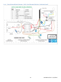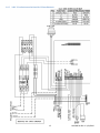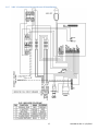
1
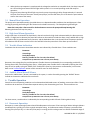
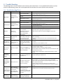
SENTRY Protect SIMPLEX PANEL Installation and Operation Manual For Wireless and Explosion Proof Pumps Environment One Corporation Table of Contents 1 2 Overview ......................................................................................................................................................................... 3 Wiring Instructions .......................................................................................................................................................... 4 2.1 Alarm Dry Contacts ................................................................................................................................................. 4 2.2 Switch Over Dry Contacts – to be used with an E/One Remote Sentry (optional) ................................................. 4 3 Startup and System Initialization .................................................................................................................................... 4 3.1 DIP Switch ............................................................................................................................................................... 4 4 5 User Interface Membrane............................................................................................................................................... 5 Normal Operation ........................................................................................................................................................... 5 5.1 Manual Run Operation............................................................................................................................................ 6 6 5.2 High Level Alarm Operation .................................................................................................................................... 6 5.3 Trouble Alarm Indication ........................................................................................................................................ 6 5.4 Audible Alarm Manual Silence ................................................................................................................................ 6 Trouble Operation........................................................................................................................................................... 6 6.1 Brownout Operation ............................................................................................................................................... 6 6.2 Overvoltage Operation ........................................................................................................................................... 7 6.3 Faulty Watt-meter Operation ................................................................................................................................. 7 6.4 Run Dry Operation .................................................................................................................................................. 7 6.5 Overpressure Operation ......................................................................................................................................... 7 6.6 Alarm Circuit Protection.......................................................................................................................................... 7 7 8 Wireless and Explosion Proof Pump Operation .............................................................................................................. 8 Trouble Shooting ............................................................................................................................................................. 9 8.1 Troubleshooting Chart ............................................................................................................................................ 9 9 Appendix ....................................................................................................................................................................... 11 9.1 Wiring Diagrams .................................................................................................................................................... 11 9.1.1 Typical Pump Wiring Diagram – 240V 2-Leg (Extreme Hardwired) .............................................................. 11 9.1.2 Typical Pump Wiring Diagram – 240V 2-Leg (Extreme Wireless / Explosion Proof) ..................................... 12 9.1.3 Typical Pump Wiring Diagram – 240V 1-Leg (Extreme Hardwired) .............................................................. 13 9.1.4 Typical Pump Wiring Diagram – 240V 1-Leg (Extreme Wireless / Explosion Proof) ..................................... 14 9.1.5 240V, 2-leg basic panel wiring (for US installations) ..................................................................................... 15 9.1.6 240V, 2-leg optional panel wiring (for US installations) ............................................................................... 16 9.1.7 240V, 1-leg basic panel wiring (for non-US installations) ............................................................................. 17 9.1.8 240V, 1-leg with optional generator receptacle, manual transfer switch (for non-US installations)........... 18 2 NA0269P11 REV B 3/23/2015 1 Overview This manual provides information on the operation and use of Environment One Simplex Protect Panels, and applies to panels configured with printed circuit board assembly P/N NB0189Gxx. For panel configurations’ beginning with ‘SD3...’this manual applies to product with an approximate manufacture date of 10/2011 or later. For all other configurations this manual applies to product with an approximate manufacture date of 03/2012 or later. If unsure of the configuration of your panel, contact E/One factory for assistance. The Sentry Protect panel is an Environment One full-featured Alarm/Monitor panel. The Sentry Protect panel monitors for the following operating conditions: Pump Run Dry Condition – Pump running out of water Pump Overpressure Condition – Pump operating at abnormally high wattage level Brownout Condition – Mains voltage under 12% of nameplate rating Overvoltage Condition – Mains voltage above 12% of nameplate rating High Liquid Level The Sentry Protect Panel displays pump status by means of the following indicators: Normal LED (Green) Pump Running LED (Green) High Level Alarm LED (Red) Run Dry LED (Amber) Overpressure LED (Amber) Brownout LED (Amber) (includes Overvoltage) The following are the hardware features: IP65 / NEMA 4X Rated Enclosure Enclosure made from Thermoplastic Polyester Separate Alarm and Pump Circuit Breakers Audible & Visual Alarm indicators (Silence for Audible Alarm) Manual Pump Run Button Remote Sentry Alarm Dry Contacts – Normally Open (Can operate with or without power. Intended for use with Environment One Remote Sentry, sold separately) Alarm Dry Contacts – Normally Open (Requires alarm board to have power) Once the Sentry Protect Panel is properly installed by mounting and wiring the panel per the instructions on the enclosure door, it is ready to operate. No further setup is required. 3 NA0269P11 REV B 3/23/2015 2 Wiring Instructions WARNING – the E/One Alarm and Control panel is a high voltage system that controls power to an electric motor. Care should be taken whenever performing service on the panel to avoid the risk of electrical shock and/or damage to property. Because power may be supplied by multiple sources, circuit breakers alone may not be sufficient to provide adequate protection. Due to the many different optional features, the Sentry Protect panel wiring can change from model to model. All wiring shall be done in accordance with the wiring decal on the inside cover of the panel enclosure. Several examples of typical wiring can be found in the Appendix of this manual. 2.1 Alarm Dry Contacts Warning! These dry contacts are capable of a maximum of 2A. Connections that exceed this maximum value can cause permanent damage to the printed circuit board within the panel. The Sentry Protect panel is equipped with one set of dry contacts that coincide with the following alarm indications: High Water Level Run Dry (after third failed re-try) Overpressure (after third failed re-try) These dry contacts will close upon detection of any of the above listed events and remain closed until the condition is removed or cleared. 2.2 Switch Over Dry Contacts – to be used with an E/One Remote Sentry (optional) Warning! These dry contacts are designed to be used in conjunction with an E/One Remote Sentry device, and are capable of a maximum of +24VDC and 2A. Connections that exceed these maximum values can cause permanent damage to the printed circuit board within the panel. The Sentry Protect panel is equipped with one set of switch over dry contacts. If power is applied to the panel these contacts respond just as the Alarm Dry Contacts described above. When connected to an E/One Remote Sentry, that device will respond with an audible and visual alarm in conjunction with above indicated alarm conditions. If power to the panel is lost these contacts are ‘switched over’ to connect directly to the alarm switch in the pump. In this configuration, the Remote Sentry device will respond with an audible and visual alarm any time the alarm switch closes, allowing the use of water even during a power outage. When power is restored to the panel, these dry contacts will switch back to their normal position. If used with a wireless grinder pump, the remote sentry will indicate an alarm immediately when the power to the pump is lost; it will be unable to determine the state of the alarm switch as is the case with a hardwired pump. 3 Startup and System Initialization The Sentry Protect panel comes from the factory ready to use and requires no special setup. However, verification of the following setting is recommended. 3.1 DIP Switch The Sentry Protect panel uses a four position miniature switch (DIP switch) located on the printed circuit board within the panel (labeled S1). These switches configure the Sentry Protect Plus for the operating environment in which the panel is being installed. From left to right, the first three positions configure the voltage setting as shown in the table below. The right most position is used to configure the panel for use with a wireless grinder pump (refer to the Wireless and Explosion Proof Pump Operation section of this manual for more information). In the following voltage selection table, “U” represents a switch in the Up (ON) position and ‘D’ represents a switch in the Down (OFF) position. The DIP switch must be programmed with power to the alarm board off (Alarm Breaker off). While this setting is typically performed at the factory, it is essential that the DIP switch is properly set for the AC Mains voltage applied for the panel to operate properly. 4 NA0269P11 REV B 3/23/2015 Input Voltage 240 VAC, 60 Hz 240 VAC, 50 Hz 230 VAC, 50 Hz 120 VAC, 60 Hz 200 VAC, 50 Hz RESERVED Factory Use Only 1234 UUUX UUDX UDUX UDDX DUUX DUDX, DDUX DDDX Warning! If DIP switch position 4 is not properly set for the type of pump, flooding of the station can occur. For switch position ‘4’ in all of the above settings, ‘X’ should be set to ‘D’ for hardwired pumps (factory default) or ‘U’ for wireless and E/One explosion proof pumps. For wireless pumps, this setting disables the Redundant Run feature. The reason for this is that in a wireless pump, the circuit board in the pump itself can energize the Alarm Return signal for conditions other than just a high level alarm. Refer to the Wireless and Explosion Proof Pump Operation section of this manual for more information. 4 User Interface Membrane The Sentry Protect panel includes a user interface to indicate the various operating and trouble conditions (see Figure 1). Three system status LED’s indicate the current pump status and indicate the various operating conditions. These are ‘Normal’, ‘Pump Running’ and ‘High Level Alarm’. Three trouble LED’s are used to indicate the various trouble conditions (Run Dry, Overpressure, Brownout / Overvoltage). All LED’s are controlled automatically by the system. A ‘Run’ button is available for manually running the pump. Figure 1 – User Interface Membrane 5 Normal Operation Under normal operating conditions, the Sentry Protect panel will perform as follows when power is applied: 1. During the boot-up period, all panel indications and outputs will be OFF except for the Alarm Lamp and the Panel Contactor. 5 NA0269P11 REV B 3/23/2015 2. When the boot-up sequence is complete and the voltage has settled to an acceptable level, the Alarm Lamp will turn off and the green Normal LED will light and the panel is in its normal operating mode and ready for operation.. 3. The green Pump Running LED will light any time the pump is operating (a delay of approximately 1-2 seconds will occur from the time the motor actually starts/stops, until the LED reacts; this is the time the panel takes to confirm the state of the motor). 5.1 Manual Run Operation The pump can be operated manually (provided there are no detected trouble conditions that would prevent it from running) by pressing and holding the ‘Run’ button on the dead-front overlay. The Pump Running LED will light. Note that it may take a few seconds for the Run button to turn on the pump and Pump Running LED. Releasing the button will stop the pump. 5.2 High Level Alarm Operation A High Level Alarm is initiated if the liquid level in the tank reaches the high level as determined by the Alarm pressure switch. If a High Level is detected, the panel will indicate an alarm which includes the Alarm Lamp, Audible Alarm, High Level Alarm LED, Dry and Remote Sentry Contacts, and the Redundant Run circuit that will force the pump to operate. All indications will self clear once the level in the tank falls below the preset limit of the Alarm pressure switch. 5.3 Trouble Alarm Indication Conditions that do not warrant immediate attention are indicated by a Trouble Alarm. These conditions are: Brownout Overvoltage Faulty Watt-meter Run Dry (Trouble for first 3 re-tries, then Alarm) Overpressure (Trouble for first 3 re-tries, then Alarm) Brownout, Overvoltage, Run Dry and Overpressure Trouble Alarms are indicated by the corresponding trouble LED, a flashing Normal LED, and a flashing Alarm Lamp. A faulty watt-meter Trouble Alarm is indicated by flashing the alarm lamp as well as rapidly cycling ALL THREE of the Trouble LED’s (Run Dry, Overpressure and Brownout) in succession. Refer to the Trouble Operation section of this manual for more on these features. 5.4 Audible Alarm Manual Silence Anytime the audible alarm / buzzer is activated by the system, it can be silenced by pressing the ‘SILENCE’ button located on the exterior underside of the enclosure. 6 Trouble Operation Several less serious operating conditions can be detected and indicated to warn of pending, more serious faults. These conditions do not warrant an immediate response and may clear themselves given time. These conditions are: Brownout Overvoltage Faulty Watt-meter Run Dry (Trouble for first 3 re-tries, then Alarm) Overpressure (Trouble for first 3 re-tries, then Alarm) For these events, a trouble alarm is indicated by the corresponding trouble LED and a flashing Alarm Lamp. 6.1 Brownout Operation Brownout is a motor protection feature that will disable power to the motor if the incoming AC Mains Voltage is below a predefined limit, typically 12% of the nominal nameplate rating. In the Brownout mode, the pump is prevented from starting (if the pump is off), or is shut off (if the pump is running) until the voltage returns to within the desired range of 6 NA0269P11 REV B 3/23/2015 operation, typically 10% of the nominal nameplate rating. When in the Brownout Protection mode, the panel will disable power to the pump, whether the motor is running or not, and the amber Brownout LED will light. 6.2 Overvoltage Operation Overvoltage is a motor protection feature that will disable power to the motor if the incoming AC Mains Voltage is above a predefined limit, typically 12% of the nominal nameplate rating. In the Overvoltage mode, the pump is prevented from starting (if the pump is off), or is shut off (if the pump is running) until the voltage returns to within the desired range of operation, typically 10% of the nominal nameplate rating. When in the Overvoltage Protection mode, the panel will disable power to the pump whether the motor is running or not, and the amber Brownout LED will light (Overvoltage and Brownout share the lone ‘Brownout’ LED). 6.3 Faulty Watt-meter Operation A faulty watt-meter indicates that the Protect Panel has lost its ability to detect any of the following conditions: Brownout, Overvoltage, Run Dry, and Overpressure. This will be indicated by flashing the alarm lamp as well as rapidly cycling ALL THREE of the Trouble LED’s (Run Dry, Overpressure, Brownout) in succession. If this condition is present, contact E/One service personnel. While the pump can still operate in this mode, there is no ability to detect if any of these conditions are present; damage to the pump and/or system could occur. 6.4 Run Dry Operation Run Dry is a motor protection feature that will disable power to the motor if the power consumption falls below a predefined limit. The factory default limit is based on the DIP switch settings and may vary for different locations. This limit is affected by the incoming AC Mains Voltage; as the Voltage fluctuates from nominal, this limit is automatically adjusted in order to obtain the same perceived pump power as would be seen at nominal Voltage. When a Run Dry condition is detected, the pump is shut off and a 20 minute lockout period begins. During this time, the Run Dry LED is illuminated and the pump is not allowed to run. After the 20 minute lockout, the pump is allowed to run; if the Run Dry condition is still present, a second lockout period begins and the cycle will repeat. During the first three lockout periods, the panel will indicate a Trouble Alarm (refer to the Trouble Alarm Indication paragraph within the Normal Operation section of this manual for more information). If after the third lockout period (60 minutes) the condition has not been removed and the pump attempts to start, the panel will indicate an alarm condition including the Alarm Lamp, Run Dry LED, Dry and Remote Sentry contacts, but no Audible Alarm. The pump is retested every 20 minutes indefinitely and will self clear if a full pump cycle completes under normal conditions. If a High Level Alarm is detected at any time during the above process, the panel will respond by issuing a high level alarm, including activating a redundant run to turn on the pump. It is assumed that if a high level alarm is present, despite the Run Dry condition there is liquid in the tank and a high level alarm / redundant run is necessary. 6.5 Overpressure Operation Overpressure is a motor protection feature that will disable power to the motor if the power consumption rises above a predefined limit. The factory default limit is based on the DIP switch settings and may vary for different locations. When an Overpressure condition is detected, the pump is shut off and a 20 minute lockout period begins. During this time, the Overpressure LED is illuminated and the pump is not allowed to run regardless of the liquid level in the tank. After the 20 minute lockout, the pump is allowed to run; if the Overpressure condition is still present a second lockout period begins, and the cycle will repeat. During the first three lockout periods, the panel will indicate a Trouble Alarm (refer to the Trouble Alarm Indication paragraph within the Normal Operation section of this manual for more information). If after the third lockout period (60 minutes) the condition has not been removed and the pump attempts to start, the panel will indicate an alarm condition including the Alarm Lamp, Overpressure LED, Dry and Remote Sentry contacts, and Audible Alarm. In addition, unlike for a Run Dry condition, in Overpressure the pump will not be retested every 20 minutes indefinitely because of the buildup of pressure that occurs during each retest. After the third failed retry, the pump is disabled indefinitely until it can be serviced. If a High Level Alarm is detected at any time during the lockout sequence, the panel will respond by issuing a high level alarm, but will not issue a redundant run. 6.6 Alarm Circuit Protection Each circuit board contains circuitry to help limit any permanent damage due to a mis-wire or short within the alarm pressure switch circuit. While this does not guarantee protection in all cases, if activated, this feature acts as a resettable 7 NA0269P11 REV B 3/23/2015 fuse and will temporarily open the circuit to help prevent damage to the circuit board itself. If conditions warrant and this circuit has been activated, the panel will be unable to detect if the alarm pressure switch is closed. This condition will be indicated by a blinking Ready LED and flashing Alarm Lamp. 7 Wireless and Explosion Proof Pump Operation E/One Explosion Proof pumps cannot be used with a Protect Panel, and require a Protect Plus panel to operate properly. Warning! If DIP switch position 4 is not properly set for the type of pump, flooding of the station can occur. Refer to the DIP Switch section of this manual for more information on setting the DIP Switches. If the Protect panel is installed with a wireless pump, some panel operations will change. A pump that is classified as wireless indicates that its level controls are not hardwired. Wireless pumps level information is communicated via a wireless interface from the pressure switches to a circuit board in the core. This is unique to wireless pumps. Because of this, all wireless pumps must have the DIP switches set to X-X-X-U (refer to the DIP Switch section of this manual). This setting overrides the panels redundant run feature that would normally accompany a High Level Alarm, as Redundant Run in a wireless pump is performed by the circuit board in the pump. This circuit board uses the Alarm Return signal to communicate not only a high level alarm, but also a loss of communication (between the pump and level sensors), back to the panel. In addition, loss of pump power will also appear as an alarm from a wireless pump. Because an alarm signal from the pump may indicate more than just a high level, Redundant Run is disabled to prevent the pump from operating when it is not intended to. These features are unique to E/One wireless pumps only. 8 NA0269P11 REV B 3/23/2015 8 Trouble Shooting The following chart is meant to address some common panel related issues. For more detailed information or pump specific troubleshooting, please refer to the appropriate Service Manual or contact E/One service personnel. 8.1 Troubleshooting Chart Fault Symptom Test Possible Cause This testing may need to be done by qualified personal Check voltage at panel per manual Verify all fuses or breakers feeding the panel are on (closed) Low incoming voltage BROWNOUT Voltage being measured by PCB is too low Blown fuse or circuit breaker Verify DIP switches are correct and being read correctly by the PCB (Initialize System menu) DIP switches incorrect Board out of Calibration OVERVOLTAGE Voltage being measured by PCB is too high This testing may need to be done by qualified personal Check voltage at panel per manual Verify DIP switches are correct and being read correctly by the PCB (Initialize System menu) Verify incoming mains voltage and current match the LCD readout High incoming voltage DIP switches incorrect Board out of Calibration RUN DRY Pump runs continuously OVERPRESSURE Excessive pump pressure No pump via ON/OFF switch Pump will not run on own but will run in manual run Refer to Service Manual and perform continuity test. If wireless refer to appropriate Service Manual. Refer to Service Manual and perform Megger insulation test Short in cable, manual run circuit shorted, Equalizer/on-off switch malfunction, short in pump, alarm switch malfunction Discharge valve closed, check valve malfunction, line restriction, grinder restriction, bad motor ON/OFF switch not working, tank ventilation blocked trouble condition present. Panel will not power up LED's do not power up Overlay not plugged in or properly, no power to the board,, faulty LED's Contactor in panel will not engage Pump will not run No power to contactor coil, contactor bad Contactor in panel engages but pump will not run Pump will not run No power coming out of contactor, loose wires, pump not working Panel does not protect against fault conditions No trouble faults, pump is not disabled for Brownout, Overvoltage, Run Dry, Overpressure, etc… Panel contactor not functioning, panel contactor mis-wired, faulty PCB, DIP switches not set properly Redundant run is not working High water alarm does not run pump Panel is turned off, miswired panel, faulty PCB Remove pump from discharge and retest with no discharge (pump back into station) If problem is still present then refer to Service Manual for more testing Perform continuity test per Service Manual to determine if the switch is faulty Verify that the tank ventilation is clear Check to see that the overlay is plugged in properly, if this still does not fix try another display Check that wiring is correct per wiring schematic Check between neutral and both sides of the alarm breaker for 120v to determine if it is bad Check voltage at alarm feed, if no power at this location, replace board Check voltage at A1 to A2 coil on contractor Check continuity on contactor coil Check for power across L1 & L2 (L1 & N) to see if power is going into the contactor, if no power then check incoming and breaker Then check T1 & T2 to see if it is going through the contactor, if not then replace the contactor Check voltage at the terminal block to see if power is there If all this is ok then refer to Service Manual for trouble shooting the pump Verify DIP switches are set properly Verify wires are connected as per decal inside panel cover Verify wires are connected as per decal inside panel cover 9 NA0269P11 REV B 3/23/2015 Fault Symptom Manual run not working Manual run does not make pump run Watt-meter Failure Flashing Alarm Lamp and cycling Trouble LED’s (Run Dry, Overpressure, Brownout) Possible Cause Panel mis-wired, faulty manual run button, faulty PCB, trouble condition present Brown wires from PCB are loose or mis-wired, faulty PCB, pump breaker off or tripped (open) Test Verify wires are connected as per decal inside panel cover Verify wires are connected as per decal inside panel cover Replace PCB if necessary 10 NA0269P11 REV B 3/23/2015 9 Appendix 9.1 Wiring Diagrams 9.1.1 Typical Pump Wiring Diagram – 240V 2-Leg (Extreme Hardwired) 11 NA0269P11 REV B 3/23/2015 9.1.2 Typical Pump Wiring Diagram – 240V 2-Leg (Extreme Wireless / Explosion Proof) 12 NA0269P11 REV B 3/23/2015 9.1.3 Typical Pump Wiring Diagram – 240V 1-Leg (Extreme Hardwired) 13 NA0269P11 REV B 3/23/2015 9.1.4 Typical Pump Wiring Diagram – 240V 1-Leg (Extreme Wireless / Explosion Proof) 14 NA0269P11 REV B 3/23/2015 9.1.5 240V, 2-leg basic panel wiring (for US installations) 15 NA0269P11 REV B 3/23/2015 9.1.6 240V, 2-leg optional panel wiring (for US installations) 16 NA0269P11 REV B 3/23/2015 9.1.7 240V, 1-leg basic panel wiring (for non-US installations) 17 NA0269P11 REV B 3/23/2015 9.1.8 240V, 1-leg with optional generator receptacle, manual transfer switch (for non-US installations) 18 NA0269P11 REV B 3/23/2015 A Precision Castparts Company Environment One Corporation 2773 Balltown Road Niskayuna, New York 12309–1090 Voice: (01) 518.346.6161 Fax: 518.346.6188 www.eone.com 19 NA0269P11 REV B 3/23/2015