1
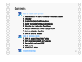
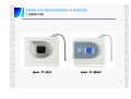
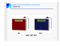
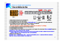
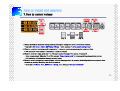
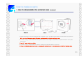
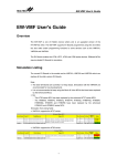
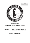
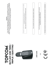
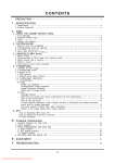
Contents
Design and characteristics of products
1. Design Plan
2. Characteristics of water ionizer
Structure and specifications of products
1. Name of external parts
2. Name of assembly parts on the back plate of the case
3. Name and function of SMPS
4. Name of the MCU board and its functions
5. Name of the scan board and its functions
6. Name of control panel
7. Flow direction of water
8. Electrical Wiring
9. Product Specifications
1
Contents
How to install and operate
1.
2.
3.
4.
5.
6.
7.
8.
Installation of a tube in the wall-mounted faucet
Contents
Product Installation Procedure
During the initial state of installation
Direction for Selecting Functions
Change of electric power supply level
How to initialize the filter
How to control volume
How to replace parts
1.
2.
3.
4.
5.
How to separate external case
Raw water valve and flow sensor
Electrolytic cell and SMPS
MCU board
Purification filter
Troubleshooting
2
Design and characteristics of products
1. DESIGN PLAN
Model : TY-2505
Model : TY-2505W
3
Design and characteristics of products
1. DESIGN PLAN
RED
BLUE
Model : MMP-5050
4
Design and characteristics of products
2. Characteristics of water ionizer
■ CPU embedded, fully automated system
■ Electrolytic antibacterial system
Every motion of an apparatus for producing electrolytic
water is controlled by semiconductor CPU that automatically find an optimal operating condition using flow
rates and water quality.
The energy generated when extracting targeted water
allows for inhibiting microorganisms from multiplying,
and automatic cleaning allows for maintaining
optimal conditions.
■ Automatic water outflow
■ Advanced water purifying filter system
Merely pressing the touch button allows you to
extract water or stop the flow of water.
The high performance primary filter and functional
secondary filter enable the optimal purifying condition
complying with raw water.
■ Voice announcement
■ Automatic Safety Diagnostic Function
Voice announcements for different functions and
safety warning voice announcements ensure safe and
convenient use.
After the installation of the product, a safety
diagnostic procedure follows to give voice
announcement if unacceptable conditions may arise.
■ Filter replacement cycle display and announcement
This product is designed to warn filter replacement
time intervals by the voice announcement and LCD
icons.
■ Automatic Extraction/Stop Function
5 minutes after the function is selected, water outflow
is stopped to prevent overflow.
(TY Model : 5 minutes, MMP Model : 10 minutes)
■ Neat and Elegant Design
This product uses a compact and deluxe design that
harmonizes with the living room.
■ Touch screen, RGB Color back light
The RGB color backlight on the touch screen allows
you to distinguish alkali water from acidic water.
■ SMPS Type Power Supply
CPU monitors the power supplied to different types of
parts, thereby ensuring this product is used in a stable
manner.
※Patent No : 10-0714055-00-00
ÎThe ion water purifier using SMPS and its control method
5
Structure and specifications of products
1. Name of external parts
Front View
[Model : TY-2505W]
[Model : TY-2505]
Rear View
[Model : MMP Series]
[Model : TY, MMP Series]
6
Structure and specifications of products
2. Name of assembly parts on the back plate of the case
출수유니
트
[1] Raw water valve: It controls the water flow of the ionizer.
[2] Flow sensor: It detects the volume of water used and the
flow rate.
[3] SMPS (Power Supply Equipment/Free Volt): It supplies
electric power to the electric parts such as the electrolytic
cell, raw water valve, etc.
[4] Electrolytic cell: It electrolyzes water.
필터브라켓
[5] Water outlet unit: The electrolyzed water flows out through
this unit.
SMPS
전해조
[6] Power switch: Power ON/OFF switch.
[7] Power cord: It supplies electricity to products.
[8] Fuse holder: It stops the flow of over-current. (250V 5A)
유량센서
전원스위
치
휴즈홀더
[9] Filter bracket: It acts as a separation film between the filter
and electronic parts.
원수밸브
전원코드
7
Structure and specifications of products
3. Name and functions of SMPS
[4]
[5]
[6]
[7]
[8]
[1] AC Input Wafer : AC85~264V 50~60Hz
[2] Fuse : 250V 5A / L:20 mm glass tube fuse
[3] Rectification condenser :
It stabilizes DC voltage when AC voltage is changed to DC voltage.
[4] Output Wafer of electrolytic cell :
It supplies power to the electrolytic cell. (cable color : see Fig. 2)
[9]
[5] 12V LED : LED is on when SMPC 12 voltage is normally generated.
[6] 5V LED : LED is on when SMPS voltage is normally generated.
[7] Speaker Wafer : It connects to the speaker (irrelevant to +/- direction).
[10]
SPARE
SPARE
It transmits the voice signal of the MCU board to the speaker through the
SMPS Wafer.
[8] Flow sensor wafer : It receives pulses (5 V square wave pulse) from the
flow sensor and transmits them to the MCU board. (see Fig. 3)
[3]
[9] SMPS Wafer : It inputs the control signal and sensor of peripheral equipment.
※ Name by SMPS wafer No.
1:PLS, 2:SP-, 3: SP+, 4:OSE, 5:VSE, 6:POL, 7:SOL1, 8:GND, 9:VCC, 10:OUT1
11:SOL2, 12:SOL3
[10] raw water valve connector: It connects to the rawwater valve (12V 400mA).
[2]
[1]
+5V
PLS
GND
[Fig. 1]
[Fig. 2]
[Fig. 3]
8
Structure and specifications of products
4. Name of the MCU board and its functions
Lot No.
Memory
[1] Memory : [AT24C02]
ME07050001
It saves information related to the operation of the water ionizer.
LCD Driver
[2] LCD Driver : This IC operates the LCD. [HT1621B]
Voice Chip
[3] Voice chip : It changes voice to Korean, English, Chinese, and Japanese by
FPC
Cable
program.
[HT86192-KEJC] - This IC plays a voice message.
CPU
[4] FPC Cable : It connects the touch screen and the MCU board.
AMP
[5] FPC Wafer : It fixes the FPC cable to the MCU board.
[6] CPU : This IC monitors all functions of the water ionizer. [16F77]
FPC
Wafer
[7] AMP : It amplifies the volume of the voice from voice chips. [LM 386]
[8] MCU wafer: It connects to the SMPS. (12P).
[9] Scan board wafer : It connects to the scan board. (5P)
P.G Down
Wafer
Scan B/D
Wafer
[10] Program wafer(5P) : It connects to the equipment when upgrading the functions
MCU
Wafer
of the MCU board.
[11] Lot No.: Production No.
[Model : TY Series]
CPU
FPC
Wafer
FPC
Cable
LCD Driver
AMP
No.1 PIN
No.12 PIN
ME07050001
※ Name by MCU wafer No.
1:PLS, 2:SP-, 3: SP+, 4:OSE, 5:VSE,
6:POL, 7:SOL1, 8:GND, 9:VCC, 10:OUT1,
P.G Down
Wafer
MCU
Wafer
[Model : MMP Series]
Voice Chip
11:SOL2, 12:SOL3
9
Structure and specifications of products
5. Name of the scan board and its functions
(applied at TY-2505 W)
[1] LED (orange) - Orange LED is on when acid water is produced.
[2] LED (blue) - Blue LED is on when alkali water is produced.
[1]
[2]
[3] Communication IC : This IC changes the serial date to parallel data.
[74HC595]
[4] Scan board wafer- It connects the scan board cable and is
connected to the MCU board.
※ Signal name by cable color.
1. Red : VCC, 2. Green : Serial Data, 3.Blue : Shift Clock
No.1 PIN
4. Gray : Store Clock, 5. Black : GND
[4]
No.5 PIN
[3]
Connect to
Scan Board
Connect to
MCU Board
10
Structure and specifications of products
6. Name of control panel
[1] Light Alkaline Mode (Drinking Water)
[1]
[2]
[2] Medium Alkaline Mode (Cooking Water)
[3]
[3] Strong Alkaline Mode (Functional Water)
[4] Purified Water Mode (Clean water)
[8]
[5] Light Acidic Mode (Face Washing Water)
[6] Strong Acidic Mode (Cleaning Water)
[4]
[9]
[7] Real Time Refresh (Cleaning Mode and Status)
[7]
[8] System Setup Mode
[10]
[9] PH Level / Filtered Quantity (Nomal Operation)
Voltage Level / Voice Volume Level (System Setup Function)
[10] Filter Replacement / Filter Initialization, Level Up/Down
[5]
[6]
[11]
[12]
(System Setup Function)
[11] Time Indicator
[Model : TY Series]
[3]
[2]
[1]
[4]
[12] Voice Mode / Volume Adjust (System Setup Function)
[5]
[6]
[9]
[12]
[10]
[8]
[7]
[11]
[Model : MMP Series]
11
Structure and specifications of products
7. Flow direction of water
[4]
[3]
[2]
[1]
[5]
[6]
[Water Pipe Diagram]
[1] Raw water input Æ Raw water valve : Water pressure of the installation place is always applied to the valve.
[2] Flow sensor Æ 1st filter : The water passing through the flow sensor flows into the 1st filter and is purified.
[3] 1st filter Æ 2nd filter: The water purified in the 1st filter is processed by the 2nd filter.
[4] 2nd filter Æ electrolytic cell: it supplies the purified water to the electrolytic cell.
[5] Electrolyzed water flows out from the alkali water outlet
- Alkali water flows out when the alkali function is selected,
- purified water flows out when the purification function is selected.
[6] Output of condensed water after electrolysis: Water opposite to the selected water flows out.
- Acid water flows out when the alkali function is selected
- Alkali water flows out when the acid water function is selected
- Purified water flows out when the purification function is selected
12
Structure and specifications of products
8. Electrical Wiring
AC Line Wiring
SMPS Wiring
AC Input 3P
SMPS Power Cable #1
Power Cord (Brown)
Fuse Holder Cable
Power Cord (Blue)
[Fig.1]
Ionizer Cell 2P
Fuse Holder Cable
SMPS Power Cable #2
[Fig. 2]
Speaker 2P
SMPS Power Cable #2
Raw Water Valve 2P
MCU B/D 12P
Flow Meter 3P
SMPS Power Cable #1
Field Ground
[Fig. 3]
AC Line Part
[1] Connect the brown and blue cables to the power switch (Fig. 1).
[2] Connect the SMPS power cable #1 to the middle hole of the
Fuse Holder
power switch (Fig. 1) and the AC socket (Fig. 3).
[3] Connect the fuse holder cable (fig. 2) to the power switch (fig. 1).
Power Switch
[4] Connect the SMPS power cable #2 (fig. 2) to the AC socket (fig. 3).
[5] Connect the green (grounding) cable of the power cord to the
AC socket (fig. 3).
AC Socket
13
Structure and specifications of products
9. Product Specifications
[Model : TY-2505]
[Model : MMP Series]
[Model : TY-2505]
14
How to install and operate
1. Installation of a tube in the wall-mounted faucet
1. Lock the main valve on the water pipe.
2. Separate the tap from the water pipe.
3. Turn the adapter to allow it to be fitted in the water pipe.
4. Assemble the tap back into the adapter.
5. Connect the valve to the adapter before connecting the
water inlet hose to the nipple.
When connecting the adaptor, finish it with teflon tape to prevent leaking. Insert
rubber seals into the pipe connecting parts.
15
How to install and operate
2. Contents
▶ Name : Water Outlet Tube
▶ Q’ty : 1 EA
▶ Name : Stem Elbow
▶ Q’ty : 2 EA
▶ Name : Tube Fixing
▶ Q’ty : 2 EA
▶ Name : Faucet Diverter
▶ Q’ty : 1 EA
The Others
▶ Name : User Manual
▶ Q’ty : 1 EA
▶ Name : PH Reagent Bottle
▶ Q’ty : 1 EA
▶ Name : Hose
▶ Q’ty : 2.5M
※ To make the best functionality, there may be a some changes without notices.
16
How to install and operate
3. How to install products
1. Place the product on the planned installation location, and turn the alkali water outlet tube clockwise to the water outlet unit positioned
on the top of the product to allow for assembling.
2. Put each steam elbow to be fitted in the raw water inlet fitting and acidic outlet fitting on the rear of the product.
3. Measure the distance between the location where the product is installed and the adapter installed in the water tap and then cut a
sufficient length of hose to allow it to be connected to the raw water inlet on the rear of the product.
4. Cut a 50-to-70cm length of drain hose and connect it to the drain on the rear of the product. Make sure the drain hose is positioned
lower than the product.
5. Allow the product to be plugged in. (If power is applied, the melody "ding dong dang" comes in.)
6. If "Alkaline or Acidic water function " is selected, auto cleaning is performed for 15 seconds, and the selected functional water comes out
of the water outlet.
- The distance between the ionizer and the tap should be less than 5 meters. (recommended water pressure: 2 ~ 4㎏f/㎠ or flow rate: 1.2ℓ/Min)
- If the distance is more than 5 meters, use a booster pump or a connection hose of 12∮ that will be needed due to decreased water pressure.
17
How to install and operate
4. During the initial state of installation
1. When the product is installed and power is applied to it, a melody comes in and the prod-uct gets ready for use in water purifying mode.
Backlight starts to blink. [TY Model : Blue↔ Amber, MMP Model : Red ↔ Violet]
2. When the targeted icon is selected in water-purifying mode, auto cleaning is performed once for about 15 seconds at the time of initial
water outflow and then water is extracted from the selected icon.
3. When you touch the icon you selected again, water supply is stopped.
※ A voice announcement saying "Under Cleaning" that is issued while the product is in use does not indicate the product operates
improperly or fails. In such cases, you can use this product after auto cleaning is done for 15 seconds.
18
How to install and operate
5. Direction for Selecting Functions
1. Mode Selection : Drinking Water Mode Selection (Light Alkaline Water)
2. Water Outflow : The selected icon flickers during water outflow. If the selected icon isn’t pressed once more, the product
automatically stops after a 5 minutes period of water outflow. [TY Series : 5Minutes, MMP Series : 10 Minutes]
3. Water Outflow Stop : Select the flickering drinking water icon. (Light Alkaline Water)
If you select a function, make sure to use your fingers in lightly touching the icons on the LCD.
19
How to install and operate
6. Change of power supply level
Level
Indicaiton
Level UP
Level UP
Level
Down
Level
Indication
Level
Down
LV 1
LV 1.5
LV 2
LV 2.5
LV 3
LV 3.5
LV 4
LV 4.5
LV 5
LV 5.5
LV 6
1. Press the setting icon on the LCD for 3 seconds to change to the setting mode.
- Back light: [TY Series : Amber, MMP Series : White], - Voice message: "This is a system setting mode."
2. Power level by function can be controlled by pressing the power level icon to which power changes, for 1.5 seconds.
- Voice guide: drinking water (alkali 1st stage) / Cooking water (alkali 2nd stage) / Functioning water (alkali 3rd stage) /
Face washing water (acid 1st stage) / Washing water (acid 2nd stage)
- LCD indication : Level indication (indicate the present set stage), changing icon (blink)
3. Press the F1 or F2 icon to adjust the stage when the icon which is to be changed blinks. (F1: ascend, F2: descend)
4. After changing it to a proper level, complete the stage control by pressing the blinking icon or return to the water out mode by
pressing the setting icon for 3 seconds.
- Back light: [TY series: blue, MMP series: green], Voice message: "Setting is completed."
Acidic 2
Acidic 1
Purified
Alkali 1
Alkali 2
Alkali 3
※ Use this mode when PH is below or above the standard.
20
How to install and operate
7. How to initialize the filter
use quantity
indication
1st Filter
1st Filter
2st Filter
use quantity
indication
[Fig. 2]
2st Filter
[Fig. 1]
[Fig. 3]
1. Replace the filter according to the filter replacing method.
[Fig. 4]
[Fig. 5]
[TY Series]
[Fig. 6]
[MMP Series]
2. Press the setting icon on the LCD for three seconds.
3. If the back light color changes and a voice announces “It is system setting mode.”, it is normally entered to the system setting mode.
4. It will be initialized if either the F1 or F2 icon, which blinks if it is over used, is pressed twice.
Once: Relevant filter voice (No. 1 filter, No. 2 filter) / Twice: It is initialized.
※ Be careful not to press an irrelevant icon. If the wrong icon is pressed, press an icon other than F1 and F2 once.
6. If it is normally initialized, the initialized icon shall stop blinking but light on.
7. Press the setting icon for three seconds.
8. It is already returned to the water flow out mode when the back light color is changed and the voice message "Setting is completed" is announced.
※ Filter cycle : No. 1 filter – 3,600 liter, No. 2 filter - 3,600 liter
※ Replacement alarm (Voice announcement comes out whenever water flows out through the filter which is used more than the requirements.)
- Icon blinking: More than 3,400 liters / Voice and icon blinks: more than 3,600 liters
9. Check how much the filter is used.
※ TY model : [Fig. 3] - initialized condition, [Fig. 4] - present use quantity indication, [Fig. 5] - replacement, initialization requirements
※ MMP model : [Fig. 6] Indicates how much the present filter is used.
21
How to install and operate
7. How to control volume
Volume
UP
Volume
Control
Volume
UP
Level
Indication
Volume
Down
Level
Indication
Volume
Control
[Fig. 3]
[Fig. 4]
Volume
Down
[Fig. 5]
1. Change the mode to the system setting mode by pressing the setting icon on the LCD for three seconds.
- Back light : [TY Series : Amber, MMP Series : White], - Voice message: "It is the system setting mode."
2. When the voice icon (volume control) is pressed for 1.5 seconds, a melody sounds and the voice icon blinks.
- LCD indication: Level indication (indicates the present set volume)
3. When the voice icon blinks, press the F1 or F2 icon to control the stage. (F1: ascend, F2 descend)
- Voice announcement: Whenever F1 or F2 is pressed, "Voice function works" is announced with a changed voice volume.
- LCD indication: it indicates the changed volume of voice.
4. When the voice is changed to a proper volume, complete the stage control by pressing the blinking voice icon or return to water
out mode by pressing the setting icon for three seconds.
- Back light : [TY Series : Blue, MMP Series : Green], voice message: "Setting is completed."
22
How to replace parts
1. How to disassemble the external case
[Fig. 1]
(common)
[Fig. 2]
[Fig. 3]
1. Remove the power cord from the power point as shown in fig. 1 or switch off the power from the back of the products.
※ Be sure to cut the power supply. Otherwise, accidents such as electric shock may occur.
2. As shown in Fig. 2, remove the case fixing screws from the four edges of the back of the products with a cross-point
screw driver.
※ use 5 ∮ cross-point screw driver.
3. As shown in Fig. 3, disassemble the case by opening front and back plates of the case.
※ Please note that the MCU board cable is connected to the MCU board on the front plate and SMPS on the back plate.
23
How to replace parts
2. Raw water valve and flow sensor
(common)
1. Disassemble the front plate case referring to the process (①~③) of
raw water valve
disassembly of external case. ※ Be sure to switch off the power.
2. Remove the raw water valve cable from the SMPS.
3. Remove the piping connected to the filter and fitting connected to the back
plate case.
4. Fasten the raw water valve fixing screw and replace the raw water valve and
then connect the screws.
Connect to
1St Filter
5. Connect the raw water valve cable to the SMPS and valve.
Connect to
Raw Water Input
※ There is no electric polarity on the raw water valve.
※ Before assembling the external case, check normal operation by supplying power.
※ Check to make sure that electric equipment is not wet.
Raw Water
Valve Cable
Flow Sensor
6. Assemble the external case in reverse order of disassembly sequence (①~③) of
the external case.
1. Disassemble the front plate case referring to the process (①~③) of
disassembly of external case.
Connect to
1St Filter
※ Be sure to switch off the power.
2. Remove the flow sensor cable from the SMPS.
3. Replace the flow sensor connected to the filter of the back plate case.
4. Connect the flow sensor cable to the SMPS.
※ Before assembling the external case, check normal operation by supplying power.
※ Check to make sure that electric equipment is not wet.
Connect to
SMPS
6. Assemble the external case in reverse order of disassembly sequence (①~③) of
the external case
24
How to replace parts
3. Electrolytic cell and SMPS
Electrolytic Cell
Purified
water Inlet
Acidic
Outlet
[Fig. 2]
Alkali
Outlet
[Fig. 1]
[Fig. 3]
1. Disassemble the front plate case referring to the process (①~③) of
disassembly of external case.
※ Be sure to switch off the power.
2. Disassemble the electrolytic cell cable connected to the SMPS and drinking
water line connected to the electrolytic cell.
3. Disassemble the electrolytic cell from the module bracket.
4. Connect the cable on the existing electrolytic cell to the new electrolytic cell.
※ When connecting the electrolytic cell cable, check if the direction depending
on the color is correct as shown in Fig. 3.
※ TY-2505, TY-2505W : 5 poles electrolytic cell (red color 2P, black color 3P)
5. Connect the drinking water line to the designated place of the electrolytic cell.
[see Fig. 1]
6. Connect the electrolytic cell to the SMPS. [see Fig. 2]
7. Assemble the external case in reverse order of disassembly sequence (①~③) of
the external case. .
S.M.P.S
1. Disassemble the front plate case referring to the process (①~③) of
disassembly of external case.
※ Be sure to switch off the power.
2. Remove the cable from the SMPS.
Ionizer
Cell
AC Input
Raw Water
Valve
3. Replace the SMPS from the module bracket.
4. Connect cables to the correct positions by referring to Fig. 1.
※ Before assembling the external case, check normal operation by supplying
power..
6. Assemble the external case in reverse order of disassembly sequence (①~③)
MCU B/D
[Fig. 1]
Flow
Meter
Speaker
of the external case.
25
How to replace parts
4. MCU board
MCU Board
1. Disassemble the front plate case referring to the process (①~③) of
disassembly of external case.
※ Check the settings of the existing MCU board. Power supply level, volume of voice
2. Fasten the fixed pieces on the front cover by the driver and separate the MCU board.
3. Disassemble the MCU board cables.
4. Fix the new MCU board on the front cover with the proper pieces.
5. Insert the MCU board cable.
※ Check the operation of the products before assembling the front/back plate case.
※ Confirm the volume of voice and PH stage.
6. Assemble the external case in reverse order of disassembly sequence (①~③) of the
external case.
[Model : TY Series]
[Model : MMP Series]
26
How to replace parts
5. Purification filter
[Fig. 1]
[Fig. 2]
[Fig. 3]
[Fig. 4]
[Fig. 5]
1. As shown in [fig.1], remove the power cord or switch off the power for safety.
2. Disassemble the filter cover from the products. Refer to [fig. 2].
※ When opening the filter cover, be careful not to get scratched from the sharp portions of the product.
3. Turn the target filter clockwise for separation.
4. Turn a new filter counterclockwise for connection.
5. assemble the filter cover. Refer to [fig. 4].
※ When reconnecting the filter cover, take care of the product units and cord.
※ Otherwise, the product may be damaged or operate improperly.
6. Plug in the power cord as shown in [Fig. 5] or switch on power.
27
Troubleshooting
1. When power is off
Check points : check power cut, power switch, fuse, SMPS LED, SMPS condenser
1) Check power cut : Is power on in the room? ⇒ Yes : Check the power switch and power cord. No : Reconfirm if it is not a power cut.
2) Power switch : Is the power switch on the back of the product kept pressed? ⇒
Yes: Press power switch. No.: Check fuse conditions.
3) Check fuse : Check fuse conditions in the fuse holder and SMPS.
- Is the line fuse in the fuse glass tube cut? ⇒ Yes: Replace it with new fuse (250V 5A 20mm). No: Check the SMPS LED.
- Does the buzzer sound when checking both ends of the fuse with a tester in buzzer mode?
⇒ Yes: Check the SMPS LED. No: Replace it with a new fuse (250V 5A 20mm).
4) Check SMPS LED
- Are all LEDs (5 V and 12 V) off ⇒ Yes: Check the voltage of the SMPS AC socket.
⇒ Is the voltage 220V? ⇒ Yes: Replace the SMPS. No: Check the conditions of power parts.
- If either 5 V or 12 V LED is off, replace the SMPS as it is not good.
- If both 5V and 12V LED are on, check the MCU board voltage and cable conditions.
⇒ If the voltage of the MCU board is 5 V, replace it. Otherwise, check the MCU board's cable conditions.
5) Confirm SMPS condenser : Is the upper part of the condenser swollen? ⇒ Yes: Replace the SMPS. No: It is normal.
2. Voice and melody do not sound
Check points: Check whether the voice function is released or not. Check voice volume, PCB conditions on the MCU board, and the speaker.
1) Release of voice function: Is the voice icon on the front LCD set to voice released? ⇒ Yes: Set voice function. No.: Adjust voice volume.
2) Voice control: Does a "Ding" sound occur when volume is adjusted in the system setting mode?
⇒ Yes: Adjust it to the proper volume. No: Check the PCB on the MCU board.
3) Check PCB on the MCU board: Are any PCB parts damaged? ⇒ Yes: Replace the MCU board. No: Check the speaker.
4) Check speaker: Is the speaker broken? ⇒ Yes: Replace the speaker, No: Check the conditions of the MCU board cable and speaker cable.
5) Check cable conditions: Is the connection condition of the cable bad? ⇒ Yes: Improve connector connection conditions or replace the cable.
28
Troubleshooting
3. When the back light does not light
Check points : Check LCD lighting conditions, soldering conditions, back light lighting conditions.
1) LCD lighting conditions: Is the LCD icon indicated? ⇒ Yes: Bad back light (replace MCU board) No: Check power supply conditions.
2) Check soldering conditions: Are the soldering conditions of the PCB on the MCU board good?
⇒ Yes: Bad back light conditions (replace MCU board) No: Cold soldering (replace MCU board) soldering
3) Back light lighting conditions: Are the blue and orange lights on in turn? ⇒ Yes: Normal, No: Replace the MCU board.
※ Before replacing the MCU board, check it again by supplying power once more.
4. When LCD is not normally indicated
Check points: LCD lighting conditions, soldering conditions
1) LCD lighting conditions : Is the LCD icon normally indicated?
⇒ Yes: Normal, No.: Check the soldering condition of the PCB on the MCU board.
2) Check soldering conditions: Is the soldering of PCB on the MCU board good?
⇒ Yes: Bad LCD (replace MCU board) No. Cold soldering (replace MCU board)
※ Before replacing the MCU board, check it again by supplying power once more.
5. Function does not work even though function is operated
Check points: Check touch screen and PCB
1) Check touch screen
- Is the specific button on the touch screen not working? ⇒ Yes: Replace the MCU board or check cable connection conditions.
- Does the specific function not automatically work when power is supplied again?
⇒ Yes: Replace the MCU board or check cable connection conditions.
- Does the specific function not automatically work when power is supplied again?
⇒ Yes: Replace the MCU board or check cable connection conditions.
2) Check PCB
- Is the FPC cable connection condition bad? ⇒ Yes: Reconnect the cable. No: Check the humidity of the PCB.
- Is the PCB wet? ⇒ Yes: Remove humidity and check it again. No: Replace the MCU board.
29
Troubleshooting
6. When electrolysis does not work well
Check points: raw water conditions, power supply stages
1) Check raw water conditions: Does the water change to a yellow color when raw water is PH tested?
⇒ Yes: Ascend power supply stage. No: Confirm the power supply stage.
2) Power supply stage: Is the power supply stage too low?
⇒ Yes: Ascend power supply stage, No: Check the voltage supplied to the electrolytic cell.
3) Check the voltage supplied to the electrolytic cell: Is the voltage supplied to the electrolytic cell 0 V?
⇒ Yes: Check OUT 1 signal on the MCU board. No: It is normal.
4) Check the MCU board signal: Is the OUT 1 signal of MCU board 5 V?
⇒ Yes: Check OUT 1 signal on the MCU board connector on the SMPS side. No.: Replace the MCU board.
5) Check OUT 1 signal on the SMPS side: Is the OUT 1 signal on the SMPS side 5 V?
⇒ Yes: Replace the SMPS. No. Replace the MCU board cable.
7. When electrolysis works very well
Check points: raw water conditions, power supply stage
1) Check raw water conditions: Does the water change to a purple color (alkali color) when it is PH tested?
⇒ Yes: Descend power supply stage. No: Check the power supply stage.
2) Power supply stage: Is the power supply stage too high?
⇒ Yes: Descend power supply stage. No.: Check the filter replacement period.
3) Check filter replacing period: Was the filter replaced not long ago?
⇒ Yes: It is normal.
※ PH may be high when less than 200 liters were filtered after replacing the old filter. This is due to active carbon.
30
Troubleshooting
8. When the "water is cut" voice sounds
Check points : raw water supply conditions, check raw water valve, check raw water valve cable, check flow sensor
1) Check raw water conditions : Is the raw water properly supplied from the tap?
⇒ Yes: Check the raw water valve No. It is normal
2) Check raw water valve: Is the voltage supplied to the raw water valve 12 V?
⇒ Yes: The flow sensor or raw water valve is bad. No: Check the raw water valve cable.
3) Check raw water valve cable: Are the cables connected to the correct positions?
⇒ Yes: Check the SOL 1 signal on the MCU board. NO. Connect it to the correct positions.
4) Check flow sensor:
- Is the voltage supplied to the flow sensor 5 V? ⇒ Yes: It is normal. No.: Check SMPS.
- Is the voltage of the signal line of the flow sensor between 1 and 4 V? ⇒ Yes. It is normal. No.: Replace flow sensor.
※ raw water piping: when the length of piping is more than 5 meters :
use 12∮ pipes or install a booster pump before the ionizer to increase water pressure.
9. When the "water pressure is too high" voice sounds
Check points: Check raw water conditions
1) Check water pressure: Is the water pressure above 5㎏f/㎠?
⇒ Yes: Adjust raw water pressure and the adaptor valve. No. It is normal.
10. Water leaks from the ionizer
Check points: check internal piping and parts conditions
1) Check piping conditions: Are the pipes between parts correctly connected?
⇒ Yes: Check parts conditions. No: Correct piping
2) Check parts conditions: Are there damaged parts?
⇒ Yes: Replace damaged parts. No: Check the voltage supplied to the electrolytic cell.
3) Check voltage supplied to electrolytic cell: Is the voltage supplied to the electrolytic cell 0 V?
⇒
No: It is normal.
31
Troubleshooting
11. Alkali water does not come out even when alkali water is pressed.
Check points: refer to No 6 in troubleshooting, when electrolysis does not work well.
12. Acid water does not come out even when acid water is pressed.
Check points: refer to No 6 in troubleshooting, when electrolysis does not work well.
13. The LED back light blinks and changes to blue and orange colors in turn.
Check points: check automatic cleaning conditions.
Automatic cleaning conditions : when 30 liter is used, when power is supplied again, when it is not used for 12 hours
1) Is it appropriate for automatic cleaning conditions? ⇒ Yes: It is normal. No.: Cleaning works when power is supplied again.
2) Does it continuously blink after cleaning? ⇒ Yes: Replace the MCU board, No: It is normal.
14. Cleaning works while alkali and acid water comes out
Check points: LED back light, Check cleaning conditions, mistake of touch operation
Automatic cleaning conditions: when 30 liter is used, when power is supplied again, when it is not used for 12 hours
1) Automatic cleaning: Does it use about 30 liters? ⇒ Yes: It is normal, No: Check other conditions.
2) Power resupply: Was the power supplied to the ionizer again? ⇒ Yes: It is normal, No: Check other conditions.
3) Waiting time: Was it inactive for more than 12 hours? ⇒ Yes: It is normal. No.: Check conditions after the cleaning operation.
4) Touch operation: Is the touch operation wrong? ⇒ Yes: It is normal. No: Check other conditions.
※ Cleaning operation stops if the cleaning icon is pressed for one second when cleaning operation is required to stop.
5) Check the LED back light in the waiting conditions of water flow after completion of the cleaning operation.
- Does the LED back light blink in blue and orange colors in turn? ⇒ Yes: Replace the MCU board, No.: It is normal.
32
Troubleshooting
15 When connecting the ionizer to underground water
※ Explain to customers the details of what happens when connecting the ionizer to an underground water supply or
when installing the ionizer after checking the quality of water.
1) Information to be relayed to customers
- The ionizer is affected by the quality of the raw water supplied and it is made to be suitable for raw water.
- The quality of underground water is largely affected by weather conditions such as drought, flood, neighboring conditions
(plants, etc.) and is always subject to change.
- The PH may change due to environmental effects even though the PH of alkali water is adjusted to the utmost.
- Installation may not be possible if the quality of underground water is bad.
- Installation is possible if the quality of underground water is suitable for drinking. PH may be high and white sediments
may appear when water is stored. Explain to the customers that these sediments are not harmful.
16. When more water flows out from the drainage than the alkali water outlet
Check points: control the hole of the drainage hose
1) Check water pressure : Is the water pressure acceptable? When water pressure is low, more water comes out from drainage.
※ Recommended water pressure: 2 ~ 3㎏f/㎠, Water flolw: 1.2ℓ/Min
- How to adjust the hole : Heat the inner side of the hose five centimeters from the end using a lighter or other heating equipment.
After it has been properly heated, pull the ends of the hose by hand to enlarge the hole.
Connect the enlarged hole to the ionizer. Adjust the hole's size and position depending on the water flow rate.
※ Do not burn the drinking hose line during heating. Recommended rate: 7:3.
33
Troubleshooting
17. When the scan board does not normally work
Check items: check the PCB on the scan board, check the scan board cables.
1) Check the LED on the scan board :
- Is the LED on the scan board off during waiting conditions? ⇒ Yes: Replace the scan board. No: It is normal.
- Are all RED lights off? ⇒ Yes: Check the scan board cable.
- Does the LED on the scan board light up when water flows out? ⇒ Yes: Check the scan board cable and connector. No: It is normal.
2) Check the scan board cable: Is the connection of the scan board and the MCU board properly done one by one?
⇒ Yes: It is normal. No: Replace the scan board cable.
34