1
2004 LEGACY SERVICE MANUAL
QUICK REFERENCE INDEX
BODY SECTION
This service manual has been prepared
to provide SUBARU service personnel
with the necessary information and data
for the correct maintenance and repair
of SUBARU vehicles.
This manual includes the procedures
for maintenance, disassembling, reassembling, inspection and adjustment of
components and diagnostics for guidance of experienced mechanics.
Please peruse and utilize this manual
fully to ensure complete repair work for
satisfying our customers by keeping
their vehicle in optimum condition.
When replacement of parts during
repair work is needed, be sure to use
SUBARU genuine parts.
All information, illustration and specifications contained in this manual are
based on the latest product information
available at the time of publication
approval.
FUJI HEAVY INDUSTRIES LTD.
HVAC SYSTEM
(HEATER, VENTILATOR AND A/C)
AC
HVAC SYSTEM (AUTO A/C)
(DIAGNOSTICS)
AC(diag)
AIRBAG SYSTEM
AB
AIRBAG SYSTEM (DIAGNOSTICS)
AB(diag)
SEAT BELT SYSTEM
SB
LIGHTING SYSTEM
LI
WIPER AND WASHER SYSTEMS
WW
ENTERTAINMENT
ET
COMMUNICATION SYSTEM
COM
GLASS/WINDOWS/MIRRORS
GW
BODY STRUCTURE
BS
INSTRUMENTATION/DRIVER INFO
IDI
SEATS
SE
SECURITY AND LOCKS
SL
SUNROOF/T-TOP/CONVERTIBLE TOP
(SUNROOF)
SR
EXTERIOR/INTERIOR TRIM
EI
EXTERIOR BODY PANELS
EB
G2320GE7
2003 LEGACY SERVICE MANUAL
QUICK REFERENCE INDEX
BODY SECTION
CRUISE CONTROL SYSTEM
CC
CRUISE CONTROL SYSTEM
(DIAGNOSTICS)
CC(diag)
IMMOBILIZER (DIAGNOSTICS)
IM(diag)
LAN SYSTEM (DIAGNOSTICS)
LAN(diag)
G2320GE7
IMMOBILIZER (DIAGNOSTICS)
IM(diag)
1.
2.
3.
4.
5.
6.
7.
8.
9.
10.
Page
Basic Diagnostic Procedure ........................................................................2
General Description ....................................................................................4
Electrical Component Location ...................................................................6
Immobilizer Control Module I/O Signal........................................................7
Subaru Select Monitor.................................................................................8
Read Diagnostic Trouble Code (DTC) ........................................................9
Clear Memory Mode..................................................................................10
Diagnostics Chart for Immobilizer Indicator Light......................................11
List of Diagnostic Trouble Code (DTC) .....................................................15
Diagnostic Procedure with Diagnostic Trouble Code (DTC) .....................17
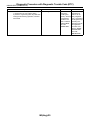
Basic Diagnostic Procedure
IMMOBILIZER (DIAGNOSTICS)
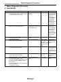
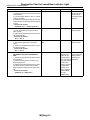
1. Basic Diagnostic Procedure
A: PROCEDURE
Step
CHECK IMMOBILIZER WARNING LIGHT.
1) Turn the ignition switch to “OFF” or “ACC”.
2) Wait for more than 60 seconds.
Check
Does the immobilizer warning
light blink?
2
CHECK KEY SWITCH.
Remove the key from ignition switch.
Does the immobilizer warning Go to step 3.
light blink within 1 second after
removing ignition key?
3
CHECK IMMOBILIZER WARNING LIGHT.
Turn the ignition switch to ON.
CHECK ENGINE START.
Turn the ignition switch to START.
Does the immobilizer warning
light off?
Does the starter operate?
5
CHECK ENGINE START.
Turn the ignition switch to START.
Does the starter operate?
6
CHECK ENGINE START.
Turn the ignition switch to START.
Does the engine start?
7
CHECK INDICATION OF DTC ON DISPLAY. Is the DTC displayed on
screen?
1) Turn the ignition switch to OFF.
2) Connect the Subaru Select Monitor to data
link connector. <Ref. to IM(diag)-8, Subaru
Select Monitor.>
3) Turn the ignition switch and Subaru Select
Monitor switch to ON.
4) Read DTC on display.
1
4
IM(diag)-2
Yes
Go to step 2.
Go to step 5.
Check the LAN
communication circuit. <Ref. to
LAN(diag)-2, Basic
Diagnostic Procedure.>
Go to step 6.
Immobilizer system is OK.
Go to step 8.
No
Check the immobilizer warning light
circuit. <Ref. to
IM(diag)-11,
CHECK IMMOBILIZER INDICATOR CIRCUIT,
INSPECTION,
Diagnostics Chart
for Immobilizer
Indicator Light.>
Check the key
switch circuit.
<Ref. to IM(diag)13, CHECK KEY
SWITCH CIRCUIT, INSPECTION, Diagnostics
Chart for Immobilizer Indicator
Light.>
Go to step 4.
Check the DTC
display (body integrated unit). Go to
step 7.
Check the LAN
communication circuit. <Ref. to
LAN(diag)-2, Basic
Diagnostic Procedure.>
Check the DTC
display (ECM). Go
to step 7.
Repair the related
parts.
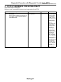
Basic Diagnostic Procedure
IMMOBILIZER (DIAGNOSTICS)
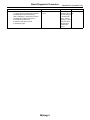
8
Step
PERFORM THE DIAGNOSIS.
1) Inspect using the “Diagnostic Procedure
with Diagnostic Trouble Code (DTC)”.
<Ref. to IM(diag)-17, Diagnostic Procedure
with Diagnostic Trouble Code (DTC).>
2) Repair the trouble cause.
3) Perform clear memory mode.
4) Read DTC again.
Check
Is the DTC displayed on
screen?
IM(diag)-3
Yes
No
Inspect using the Finish the diagno“Diagnostic Proce- sis.
dure with Diagnostic Trouble Code
(DTC)”. <Ref. to
IM(diag)-17, Diagnostic Procedure
with Diagnostic
Trouble Code
(DTC).>
General Description
IMMOBILIZER (DIAGNOSTICS)
2. General Description
A: CAUTION
CAUTION:
• All airbag system wiring harnesses and connectors are yellow. Do not use the electrical
test equipment on these circuits.
• Be careful not to damage the airbag system
wiring harness.
• While diagnostic items are being checked, do
not operate radios, portable telephones, etc.
which emit electromagnetic waves near or inside the vehicle.
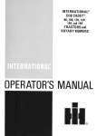
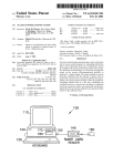
• When repeatedly turning the ignition switch
to ON or OFF while diagnostic items are being
checked, it should be switched in cycles of
“ON” for at least 5 seconds → “OFF” for at least
8 seconds.
ON
(1)
OFF
5
8
(2)
IM-00003
(1) Ignition switch position
(2) Sec.
IM-00001
• When turning the ignition switch to ON or
OFF while diagnostic items are being checked,
do not allow keys with different ID codes close
to the ignition switch. If the ignition key is in a
key holder, remove it from the holder before
carrying out diagnosis.
• If the engine fails to start with a registered ignition key, detach the ignition key from ignition
switch and wait for approx. 1 second until immobilizer indicator light begins to flash. And
then start the engine again.
• Before checking the diagnostic items, obtain
all keys for the vehicle to be checked possessed by owner.
IM-00002
IM(diag)-4
General Description
IMMOBILIZER (DIAGNOSTICS)
B: PREPARATION TOOL
1. SPECIAL TOOL
ILLUSTRATION
TOOL NUMBER
24082AA230
DESCRIPTION
CARTRIDGE
REMARKS
Troubleshooting for electrical system.
22771AA030
SUBARU SELECT
MONITOR KIT
Troubleshooting for electrical system.
• English: 22771AA030 (Without printer)
• German: 22771AA070 (Without printer)
• French: 22771AA080 (Without printer)
• Spanish: 22771AA090 (Without printer)
ST24082AA230
ST22771AA030
2. GENERAL TOOL
TOOL NAME
Circuit tester
REMARKS
Used for measuring resistance, voltage and ampere.
IM(diag)-5
Electrical Component Location
IMMOBILIZER (DIAGNOSTICS)
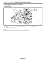
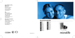
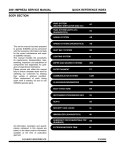
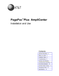
3. Electrical Component Location
A: LOCATION
(4)
(2)
(1)
(3)
IM-00083
(1)
(2)
Antenna
Immobilizer indicator light (LED
bulb)
(3)
Body integrated unit
NOTE:
Body integrated unit location for RHD model is symmetrically opposite.
IM(diag)-6
(4)
Transponder
Immobilizer Control Module I/O Signal
IMMOBILIZER (DIAGNOSTICS)
4. Immobilizer Control Module
I/O Signal
A: WIRING DIAGRAM
1. IMMOBILIZER
<Ref. to WI-246, WIRING DIAGRAM, Immobilizer
System.>
IM(diag)-7
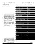
Subaru Select Monitor
IMMOBILIZER (DIAGNOSTICS)
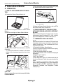
5. Subaru Select Monitor
5) Turn the ignition switch to ON (engine OFF), and
the Subaru Select Monitor switch to ON.
A: OPERATION
1. HOW TO USE SUBARU SELECT MONITOR
(1)
1) Prepare the Subaru Select Monitor kit.
CC-00045
(1) Power switch
6) Using the Subaru Select Monitor, call up DTCs
and various data, then record them.
CC-00028
2) Connect the diagnosis cable to Subaru Select
Monitor.
3) Insert the cartridge to Subaru Select Monitor.
2. READ DIAGNOSTIC TROUBLE CODE
(DTC) FOR ENGINE AND BODY INTEGRATED UNIT
Refer to Read Diagnostic Trouble Code for information about how to indicate DTC. <Ref. to IM(diag)-9, Read Diagnostic Trouble Code (DTC).>
3. COMMUNICATION LINE CHECK
CC-00029
4) Connect the Subaru Select Monitor to data link
connector.
(1) Data link connector is located in the lower
portion of the instrument panel (on the driver’s
side).
IM-00084
NOTE:
The communication line between ECM and body
integrated module can be checked in “System Operation Check Mode”. This is referred to as “Communication line check”.
1) Connect the Subaru Select Monitor.
2) On the «System operation check mode» display,
select the {security system}.
3) Start the communication line check.
4) Is «Communication Line not Shorted» displayed
on screen?
If displayed, go to step 5).
If “NO”, go to step 6).
5) After diagnostic results, it is determined that the
circuit is not shorted. Finish the communication line
check.
6) If a problem is detected, repair the trouble
cause. <Ref. to IM(diag)-22, DTC P1572 IMM CIRCUIT FAILURE (EXCEPT ANTENNA CIRCUIT),
Diagnostic Procedure with Diagnostic Trouble
Code (DTC).>
(2) Connect the diagnosis cable to data link
connector.
CAUTION:
Do not connect the scan tools except for Subaru Select Monitor.
IM(diag)-8
Read Diagnostic Trouble Code (DTC)
IMMOBILIZER (DIAGNOSTICS)
6. Read Diagnostic Trouble
Code (DTC)
A: OPERATION
1. ECM
1) On the «Main Menu» display screen, select the
{Each System Check} and press the [YES] key.
2) On the «System Selection Menu» display
screen, select the {Engine Control System} and
press the [YES] key.
3) Press the [YES] key after the information of engine type is displayed.
4) On the «Engine Diagnosis» display screen, select the {Diagnostic Code(s) Display}, and then
press the [YES] key.
5) On the «Diagnostic Code(s) Display» display
screen, select the {Current Diagnostic Code(s)} or
{History Diagnostic Code(s)}, and then press the
[YES] key.
NOTE:
• For detailed operation procedure, refer to the
SUBARU SELECT MONITOR OPERATION MANUAL.
• For detailed concerning DTC, refer to the List of
DTC. <Ref. to IM(diag)-15, LIST, List of Diagnostic
Trouble Code (DTC).>
2. BODY INTEGRATED UNIT
1) On the «Main Menu» display screen, select the
{Each System Check} and press the [YES] key.
2) On the «System Selection Menu» display
screen, select the {Integ. unit mode} and press the
[YES] key.
3) Press the [YES] key after the {Integ. unit mode}
is displayed.
4) On the «Integ. unit mode failure diag» display
screen, select the {Diagnostic Code(s) Display}
and press the [YES] key.
NOTE:
• For detailed operation procedure, refer to the
SUBARU SELECT MONITOR OPERATION MANUAL.
• For detailed concerning DTC, refer to the List of
DTC. <Ref. to IM(diag)-15, LIST, List of Diagnostic
Trouble Code (DTC).>
IM(diag)-9
Clear Memory Mode
IMMOBILIZER (DIAGNOSTICS)
7. Clear Memory Mode
A: OPERATION
1. ECM
1) On the «Main Menu» display screen, select the
{Each System Check} and press the [YES] key.
2) On the «System Selection Menu» display
screen, select the {Engine Control System} and
press the [YES] key.
3) Press the [YES] key after the information of engine type is displayed.
4) On the «Engine Diagnosis» display screen, select the {Clear Memory} and press the [YES] key.
5) When the ‘Done’ are shown on the display
screen, turn the Subaru Select Monitor and ignition
switch to OFF.
NOTE:
• After the memory has been cleared, the idle air
control solenoid valve must be initialized. To execute this procedure, turn the ignition switch to ON.
Wait 3 seconds before starting the engine.
• For detailed operation procedure, refer to the
SUBARU SELECT MONITOR OPERATION MANUAL.
2. BODY INTEGRATED UNIT
1) On the «Main Menu» display screen, select the
{Each System Check} and press the [YES] key.
2) On the «System Selection Menu» display
screen, select the {Integ. unit mode} and press the
[YES] key.
3) Press the [YES] key after the {Integ. unit mode}
is displayed.
4) On the «Integ. unit mode failure diag» display
screen, select the {Clear Memory} and press the
[YES] key.
5) When the ‘Done’ are shown on the display
screen, turn the Subaru Select Monitor and ignition
switch to OFF.
NOTE:
For detailed operation procedure, refer to the SUBARU SELECT MONITOR OPERATION MANUAL.
IM(diag)-10
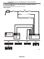
Diagnostics Chart for Immobilizer Indicator Light
IMMOBILIZER (DIAGNOSTICS)
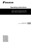
8. Diagnostics Chart for Immobilizer Indicator Light
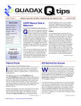
A: INSPECTION
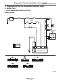
1. CHECK IMMOBILIZER INDICATOR CIRCUIT
WIRING DIAGRAM:
BATTERY
SBF-9
SBF-1
F/B No.7
RHD
LHD
IGNITION
SWITCH
F/B No.12
SBF-4
R167
13
11
R98
i102
i53
RHD
M/B No.8
LHD
COMBINATION METER
A:
i10
IMMOBILIZER
INDICATOR
LIGHT
A1
A2
A17
A:
C2
A33
A1
i84
B: B280
E
B7
C9
B22
C8
LHD : LHD MODEL
RHD : RHD MODEL
BODY INTEGRATED UNIT
C: B281
i102
A:
i10
A:
i84
i53
6 7 8 9 10
1 2 3 4 5
11 12 13 14 15 16 17 18 19 20 21 22
B: B280
1 2 3
4 5
6 7
8 9 10 11 12 13 14 15 16 17 18 19 20
21 22
23 24 25
26 27
28 29 30
1 2 3 4
5 6 7 8
9 10 11 12 13 14 15 16 17 18
1 2
3 4
5 6
7 8
9 10 11 12 13 14 15 16 17 18 19 20 21 22 23
24 25
26 27 28 29
30 31 32 33
34 35
C: B281
4 5 6 7
1 2 3
8 9 10 11 12 13 14 15 16 17 18 19
27 28
22 23
24 25 26
20 21
IM-00086
IM(diag)-11
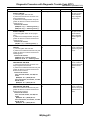
Diagnostics Chart for Immobilizer Indicator Light
IMMOBILIZER (DIAGNOSTICS)
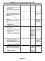
1
2
3
4
5
6
Step
CHECK IMMOBILIZER WARNING LIGHT.
1) Turn the ignition switch to OFF.
2) Disconnect the harness connector from
body integrated unit.
3) Connect the resistor (100 Ω) between body
integrated unit harness connector terminal
(i84) No. 33 and chassis ground.
CHECK BODY INTEGRATED UNIT GROUND
CIRCUIT.
Measure the resistance between body integrated unit harness connector terminal and
chassis ground.
Connector & terminal
(B280) No. 22 — Chassis ground:
(B281) No. 8, No. 9 — Chassis ground:
CHECK BODY INTEGRATED UNIT IGNITION
CIRCUIT.
1) Turn the ignition switch to ON. (engine
OFF)
2) Measure the voltage between body integrated unit harness connector terminal and
chassis ground.
Connector & terminal
(i84) No. 1 (+) — Chassis ground (−):
CHECK BODY INTEGRATED UNIT POWER
SUPPLY CIRCUIT.
1) Turn the ignition switch to OFF.
2) Measure the voltage between body integrated unit harness connector terminal and
chassis ground.
Connector & terminal
(B280) No. 7 (+) — Chassis ground (−):
(B281) No. 2 (+) — Chassis ground (−):
Check
Yes
Does the immobilizer indicator Go to step 2.
light illuminate?
No
Go to step 5.
Is the resistance less than 10
Ω?
Go to step 3.
Repair the open
circuit of body integrated unit ground
circuit.
Is the voltage more than 10 V? Go to step 4.
Check the harness
for open or short
circuit between
body integrated
unit and ignition
switch.
Is the voltage more than 10 V? Replace the body
integrated unit
<Ref. to SL-46,
Body Integrated
Unit.> and replace
the all ignition keys
(including transponder). Execute
the registration
procedure next.
Refer to “REGISTRATION MANUAL FOR
IMMOBILIZER”.
Is the voltage more than 10 V? Go to step 6.
Check the harness
for open or short
circuit between
body integrated
unit and fuse.
CHECK COMBINATION METER CIRCUIT.
1) Remove the combination meter. <Ref. to
IDI-16, Combination Meter Assembly.>
2) Measure the voltage between the combination meter harness connector terminal and
chassis ground.
Connector & terminal
(i10) No. 1, No. 2 (+) — Chassis ground (−):
CHECK COMBINATION METER CIRCUIT.
Is the resistance less than 10
Measure the resistance between body inteΩ?
grated unit harness connector terminal and
combination meter harness connector terminal.
Connector & terminal
(i84) No. 33 — (i10) No. 17:
IM(diag)-12
Check the harness
for open or short
circuit between
combination meter
and fuse.
LED bulb malfunc- Repair the hartion. Replace the ness/connector.
combination meter
case assembly.
<Ref. to IDI-17,
DISASSEMBLY,
Combination
Meter Assembly.>
Diagnostics Chart for Immobilizer Indicator Light
IMMOBILIZER (DIAGNOSTICS)
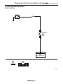
2. CHECK KEY SWITCH CIRCUIT
WIRING DIAGRAM:
BATTERY
3
M/B No.14
KEY WARNING
SWITCH
C7
4
B350
C: B281
BODY INTEGRATED UNIT
B350
1 2 3 4
C: B281
4 5 6 7
1 2 3
8 9 10 11 12 13 14 15 16 17 18 19
27 28
22 23
24 25 26
20 21
IM-00078
IM(diag)-13
Diagnostics Chart for Immobilizer Indicator Light
IMMOBILIZER (DIAGNOSTICS)
1
2
3
4
Step
CHECK POWER SUPPLY CIRCUIT.
1) Disconnect the harness connector from key
warning switch.
2) Turn the ignition switch to “ACC” or “LOCK”
(with key inserted).
3) Measure the voltage between key warning
switch harness connector terminal and chassis
ground.
Connector & terminal
(B350) No. 3 (+) — Chassis ground (−):
CHECK KEY WARNING SWITCH.
1) Insert the ignition key to ignition switch.
(OFF or ACC)
2) Measure the resistance between key warning switch terminals.
Connector & terminal
No. 3 — No. 4:
CHECK KEY WARNING SWITCH.
1) Remove the ignition key from ignition
switch.
2) Measure the resistance between key warning switch terminals.
Connector & terminal
No. 3 — No. 4:
CHECK HARNESS BETWEEN KEY WARNING SWITCH AND BODY INTEGRATED
UNIT.
1) Disconnect the harness connector from key
warning switch.
2) Disconnect the harness connector from
body integrated unit.
3) Measure the resistance between key warning switch harness connector terminal and
body integrated unit harness connector terminal.
Connector & terminal
(B350) No. 4 — (B281) No. 7:
Check
Yes
Is the voltage more than 10 V? Go to step 2.
No
Check the harness
for open or short
circuit between
key warning switch
and fuse.
Is the resistance less than 1
Ω?
Go to step 3.
Replace the key
warning switch.
Is the resistance more than 1
MΩ?
Go to step 4.
Replace the key
warning switch.
Is the resistance less than 10
Ω?
Replace the body
integrated unit
<Ref. to SL-46,
Body Integrated
Unit.> and replace
the all ignition keys
(including transponder). Execute
the registration
procedure next.
Refer to “REGISTRATION MANUAL FOR
IMMOBILIZER”.
Repair the harness between key
warning switch
and body integrated unit.
IM(diag)-14
List of Diagnostic Trouble Code (DTC)
IMMOBILIZER (DIAGNOSTICS)
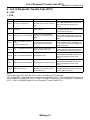
9. List of Diagnostic Trouble Code (DTC)
A: LIST
1. ECM
DTC
P0513
P1570
P1571
P1572
P1574
P1576
P1577
P1578
Item
Contents of diagnosis
Index No.
<Ref. to IM(diag)-17, DTC P0513 INCORIncorrect immobilizer key (Use of
RECT IMMOBILIZER KEY, Diagnostic ProIncorrect Immobilizer Key
unregistered key in body integrated
cedure with Diagnostic Trouble Code
unit)
(DTC).>
<Ref. to IM(diag)-18, DTC P1570
ANTENNA
Faulty antenna
ANTENNA, Diagnostic Procedure with Diagnostic Trouble Code (DTC).>
<Ref. to IM(diag)-21, DTC P1571 REFERReference code incompatibility
ENCE CODE INCOMPATIBILITY, DiagnosReference Code Incompatibility between body integrated unit and
tic Procedure with Diagnostic Trouble Code
ECM
(DTC).>
<Ref. to IM(diag)-22, DTC P1572 IMM CIREGI — Immobilizer CommuniCommunication failure between
CUIT FAILURE (EXCEPT ANTENNA CIRcation
body integrated unit and ECM
CUIT), Diagnostic Procedure with Diagnostic
(Except Antenna Circuit)
Trouble Code (DTC).>
<Ref. to IM(diag)-25, DTC P1574 KEY COMKey — Immobilizer Communica- Failure of body integrated unit to verMUNICATION FAILURE, Diagnostic Procetion
ify key (transponder) ID code
dure with Diagnostic Trouble Code (DTC).>
<Ref. to IM(diag)-25, DTC P1576 EGI CONTROL MODULE EEPROM, Diagnostic ProEGI Control Module EEPROM
ECM malfunctioning
cedure with Diagnostic Trouble Code
(DTC).>
<Ref. to IM(diag)-25, DTC P1577 IMM CONTROL MODULE EEPROM, Diagnostic ProIMM Control Module EEPROM Body integrated unit malfunctioning
cedure with Diagnostic Trouble Code
(DTC).>
Reference code incompatibility
<Ref. to IM(diag)-26, DTC P1578 METER
Meter malfunctioning
between body integrated unit and
FAILURE, Diagnostic Procedure with Diagcombination meter
nostic Trouble Code (DTC).>
NOTE:
Perform the engine DTC when the DTC except for immobilizer DTC is detected.
<Ref. to EN(H4SO 2.0)(diag)-66, List of Diagnostic Trouble Code (DTC).> <Ref. to EN(H4SO 2.5)(diag)-70,
List of Diagnostic Trouble Code (DTC).> <Ref. to EN(H4DOTC)(diag)-55, List of Diagnostic Trouble Code
(DTC).> <Ref. to EN(H6DO)(diag)-66, List of Diagnostic Trouble Code (DTC).>
IM(diag)-15
List of Diagnostic Trouble Code (DTC)
IMMOBILIZER (DIAGNOSTICS)
2. BODY INTEGRATED UNIT
DTC
B0401
Item
M collation NG
Contents of diagnosis
Reference code incompatibility between body integrated
unit and combination meter
• Incorrect immobilizer key
(Use of unregistered key in
body integrated unit)
• Faulty antenna
B0402
B0403
Immobilizer Key collation NG
E/G request NG
Communication failure
between body integrated unit
and ECM
Index No.
<Ref. to IM(diag)-26, DTC
P1578 METER FAILURE, Diagnostic Procedure with Diagnostic Trouble Code (DTC).>
<Ref. to IM(diag)-17, DTC
P0513 INCORRECT IMMOBILIZER KEY, Diagnostic Procedure with Diagnostic Trouble
Code (DTC).> <Ref. to IM(diag)18, DTC P1570 ANTENNA,
Diagnostic Procedure with Diagnostic Trouble Code (DTC).> or
<Ref. to IM(diag)-25, DTC
P1574 KEY COMMUNICATION FAILURE, Diagnostic Procedure with Diagnostic Trouble
Code (DTC).>
<Ref. to IM(diag)-22, DTC
P1572 IMM CIRCUIT FAILURE
(EXCEPT ANTENNA CIRCUIT), Diagnostic Procedure
with Diagnostic Trouble Code
(DTC).>
Relation between ECM and
DTC
P1578
• P0513
• P1570
• P1574
P1572
NOTE:
• Immobilizer system of 2.5 L EC, EK model and 3.0 L model perform the starter relay control. When the
body integrated unit detect the inconformity of reference code, immediately out put the starter relay cut signal
to ECM, and then ECM stop the starter relay operation. In this case, engine does not start, and DTC is not
recorded in ECM. Check that the engine does not start on the DTC of body integrated unit.
• DTC B0402 is recorded as freeze frame data when the ignition switch is turned to OFF. When trying to start
the engine with unregistered immobilizer key, DTC is not displayed on Subaru Select Monitor immediately.
Turn the ignition switch to OFF once and turn to ON again before checking DTC. At this time (when turning
the ignition switch to ON again), be careful that the DTC is displayed as freeze frame data even with the registered immobilizer key.
IM(diag)-16
Diagnostic Procedure with Diagnostic Trouble Code (DTC)
IMMOBILIZER (DIAGNOSTICS)
10.Diagnostic Procedure with Diagnostic Trouble Code (DTC)
A: DTC P0513 INCORRECT IMMOBILIZER KEY
DTC DETECTING CONDITION:
Incorrect immobilizer key (Use of unregistered key in body integrated unit)
1
2
Step
Check
Yes
PERFORM TEACHING OPERATION ON IG- Is the teaching operation for all END.
NITION KEY.
keys completed?
Perform teaching operation on all keys of the
vehicle. Refer to “REGISTRATION MANUAL
FOR IMMOBILIZER”.
PERFORM TEACHING OPERATION ON IG- Is the teaching operation for all END.
NITION KEY.
keys completed?
Perform teaching operation on all keys of the
vehicle. Refer to “REGISTRATION MANUAL
FOR IMMOBILIZER”.
IM(diag)-17
No
Replace the ignition keys (including transponder)
which cannot be
registered. Go to
step 2.
Replace the body
integrated unit
<Ref. to SL-46,
Body Integrated
Unit.> and replace
all the ignition keys
(including transponder). Execute
the registration
procedure next.
Refer to “REGISTRATION MANUAL FOR
IMMOBILIZER”.
Diagnostic Procedure with Diagnostic Trouble Code (DTC)
IMMOBILIZER (DIAGNOSTICS)
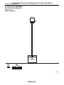
B: DTC P1570 ANTENNA
DTC DETECTING CONDITION:
Faulty antenna
WIRING DIAGRAM:
ANTENNA
C21
C20
1
2
B351
C: B281
BODY INTEGRATED UNIT
B351
1 2
C: B281
4 5 6 7
1 2 3
8 9 10 11 12 13 14 15 16 17 18 19
27 28
22 23
24 25 26
20 21
IM-00079
IM(diag)-18
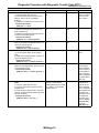
Diagnostic Procedure with Diagnostic Trouble Code (DTC)
IMMOBILIZER (DIAGNOSTICS)
1
2
3
4
5
6
Step
CHECK ANTENNA CIRCUIT.
1) Turn the ignition switch to OFF.
2) Disconnect the harness connector from
antenna. <Ref. to SL-50, Immobilizer
Antenna.>
3) Measure the resistance of antenna circuit.
Connector & terminal
(B351) No. 1 — No. 2:
CHECK ANTENNA CIRCUIT.
1) Disconnect the harness connector from
body integrated unit.
2) Measure the resistance between harness
connector and chassis ground.
Connector & terminal
(B281) No. 21 — Chassis ground:
CHECK ANTENNA CIRCUIT.
Measure the resistance between harness connector and chassis ground.
Connector & terminal
(B281) No. 20 — Chassis ground:
CHECK ANTENNA CIRCUIT.
1) Turn the ignition switch to ON. (engine
OFF)
2) Measure the voltage between harness connector and chassis ground.
Connector & terminal
(B281) No. 21 (+) — Chassis ground (−):
CHECK ANTENNA CIRCUIT.
Measure the voltage between harness connector and chassis ground.
Connector & terminal
(B281) No. 20 (+) — Chassis ground (−):
CHECK BODY INTEGRATED UNIT FUNCTION.
1) Turn the ignition switch to OFF.
2) Connect the harness connector to body
integrated unit.
3) Insert the key to ignition switch, and measure the changes in voltage between antenna
harness connectors.
Connector & terminal
(B281) No. 20 (+) — No. 21 (−):
Check
Is the resistance less than 10
Ω?
Yes
Go to step 2.
No
Replace the
antenna. <Ref. to
SL-50, Immobilizer Antenna.>
Is the resistance less than 10
Ω?
Repair the harness.
Go to step 3.
Is the resistance less than 10
Ω?
Repair the harness.
Go to step 4.
Is the voltage 0 V?
Go to step 5.
Repair the harness.
Is the voltage 0 V?
Go to step 6.
Repair the harness between
body integrated
unit and antenna,
because there is
short circuit with
battery voltage line
or ignition switch
“ON” line.
Replace the body
integrated unit
<Ref. to SL-46,
Body Integrated
Unit.> and replace
all the ignition keys
(including transponder). Execute
the registration
procedure next.
Refer to “REGISTRATION MANUAL FOR
IMMOBILIZER”.
Is the voltage −30 to 30 V?
Go to step 7.
(Approx. 0.1 second after
inserting the key) Is the voltage
0 V? (Approx. 1 second after
inserting the key)
IM(diag)-19
Diagnostic Procedure with Diagnostic Trouble Code (DTC)
IMMOBILIZER (DIAGNOSTICS)
7
Step
Check
CHECK IGNITION KEY (TRANSPONDER).
Does the engine start?
1) Remove the key from ignition switch.
2) Start the engine using other keys that have
undergone the teaching operation, furnished
with vehicle.
IM(diag)-20
Yes
Replace all the
ignition keys
(including transponder). Execute
the registration
procedure next.
Refer to “REGISTRATION MANUAL FOR
IMMOBILIZER”.
No
Replace the body
integrated unit
<Ref. to SL-46,
Body Integrated
Unit.> and replace
the all ignition keys
(including transponder). Execute
the registration
procedure next.
Refer to “REGISTRATION MANUAL FOR
IMMOBILIZER”.
Diagnostic Procedure with Diagnostic Trouble Code (DTC)
IMMOBILIZER (DIAGNOSTICS)
C: DTC P1571 REFERENCE CODE INCOMPATIBILITY
DTC DETECTING CONDITION:
Reference code incompatibility between body integrated unit and ECM
1
Step
Check
Yes
PERFORM TEACHING OPERATION ON IG- Is the teaching operation for all END.
NITION KEY.
keys completed?
Perform teaching operation on all keys of the
vehicle. Refer to “REGISTRATION MANUAL
FOR IMMOBILIZER”.
IM(diag)-21
No
Replace the ECM.
<Ref. to FU(H4SO
2.0)-34, Engine
Control Module
(ECM).> <Ref. to
FU(H4SO 2.5)-36,
Engine Control
Module (ECM).>
<Ref. to
FU(H4DOTC)-35,
Engine Control
Module (ECM).>
<Ref. to
FU(H6DO)-34,
Engine Control
Module (ECM).>
Replace the body
integrated unit
<Ref. to SL-46,
Body Integrated
Unit.> and replace
all the ignition keys
(including transponder). Execute
the registration
procedure next.
Refer to “REGISTRATION MANUAL FOR
IMMOBILIZER”.
Diagnostic Procedure with Diagnostic Trouble Code (DTC)
IMMOBILIZER (DIAGNOSTICS)
D: DTC P1572 IMM CIRCUIT FAILURE (EXCEPT ANTENNA CIRCUIT)
DTC DETECTING CONDITION:
Communication failure between body integrated unit and ECM
WIRING DIAGRAM:
BATTERY
SBF-1
SBF-4
IGNITION
SWITCH
F/B No.12
F/B No.7
SBF-9
A1
C2
B7
i84
B28
C9
A:
B18
C8
: 2.0 L TURBO MODEL,
3.0 L MODEL AND
2.5 L EC, K4, EK MODEL
B22
*2
D19 B25
: 2.0 L NA MODEL AND
2.5 L KS, KA MODEL
* *
*1
2
1
D27 B33
M/B No.8
B: B135
B: B280
ECM
D: B137
E
A:
i84
1 2
3 4
5 6
7 8
9 10 11 12 13 14 15 16 17 18 19 20 21 22 23
24 25
26 27 28 29
30 31 32 33
34 35
B: B280
C: B281
C: B281
1 2 3
4 5
6 7
8 9 10 11 12 13 14 15 16 17 18 19 20
23 24 25
26 27
28 29 30
21 22
BODY INTEGRATED UNIT
4 5 6 7
1 2 3
8 9 10 11 12 13 14 15 16 17 18 19
27 28
22 23
24 25 26
20 21
D: B137
1 2 3 4 5 6 7
8 9 10 11 12 13 14 15 16 17
18 19 20 21 22 23
24 25
28 29
30 31
26 27
B: B135
1 2
3 4 5 6 7
8 9 10 11 12 13 14 15 16 17 18 19
20 21 22 23
24 25
26 27
28 29 30 31
32 33
34 35
IM-00087
IM(diag)-22
Diagnostic Procedure with Diagnostic Trouble Code (DTC)
IMMOBILIZER (DIAGNOSTICS)
1
2
3
4
5
Step
CHECK BODY INTEGRATED UNIT POWER
SUPPLY CIRCUIT.
1) Turn the ignition switch to OFF.
2) Disconnect the harness connector from
body integrated unit.
3) Measure the voltage between body integrated unit harness connector terminal and
chassis ground.
Connector & terminal
(B280) No. 7 (+) — Chassis ground (−):
(B281) No. 2 (+) — Chassis ground (−):
CHECK BODY INTEGRATED UNIT POWER
SUPPLY CIRCUIT.
1) Turn the ignition switch to ON. (engine
OFF)
2) Measure the voltage between body integrated unit harness connector terminal and
chassis ground.
Connector & terminal
(i84) No. 1 (+) — Chassis ground (−):
CHECK BODY INTEGRATED UNIT GROUND
CIRCUIT.
1) Turn the ignition switch to OFF.
2) Measure the resistance between body integrated unit harness connector terminal and
chassis ground.
Connector & terminal
(B280) No. 22 — Chassis ground:
(B281) No. 8, No. 9 — Chassis ground:
CHECK HARNESS BETWEEN BODY INTEGRATED UNIT AND ECM.
1) Disconnect the harness connector from
body integrated unit and ECM.
2) Measure the resistance between body integrated unit harness connector terminal and
ECM connector terminal.
Connector & terminal
2.0 L non-turbo model, 2.5 L KS, KA
model
(B280) No. 18 — (B135) No. 25:
2.0 L turbo model, 3.0 L model, 2.5 L EC,
K4, EK model
(B280) No. 18 — (B137) No. 19:
CHECK HARNESS BETWEEN BODY INTEGRATED UNIT AND ECM.
Measure the resistance between body integrated unit harness connector terminal and
ECM connector terminal.
Connector & terminal
2.0 L non-turbo model, 2.5 L KS, KA
model
(B280) No. 28 — (B135) No. 33:
2.0 L turbo model, 3.0 L model, 2.5 L EC,
K4, EK model
(B280) No. 28 — (B137) No. 27:
Check
Yes
Is the voltage more than 10 V? Go to step 2.
No
Check the harness
for open or short
circuit between
body integrated
unit and fuse.
Is the voltage more than 10 V? Go to step 3.
Check the harness
for open or short
circuit between
body integrated
unit and ignition
switch.
Is the resistance less than 10
Ω?
Go to step 4.
Repair the open
circuit of body integrated unit ground
circuit.
Is the resistance less than 10
Ω?
Go to step 5.
Repair the open
circuit of harness
between body integrated unit and
ECM.
Is the resistance less than 10
Ω?
Go to step 6.
Repair the open
circuit of harness
between body integrated unit and
ECM.
IM(diag)-23
Diagnostic Procedure with Diagnostic Trouble Code (DTC)
IMMOBILIZER (DIAGNOSTICS)
6
7
8
Step
CHECK HARNESS OF COMMUNICATION
LINE.
1) Turn the ignition switch to ON. (engine
OFF)
2) Measure the voltage between body integrated unit harness connector terminal and
chassis ground.
Connector & terminal
(B280) No. 18, No. 28 (+) — Chassis
ground (−):
CHECK HARNESS OF COMMUNICATION
LINE.
Measure the voltage between harness connector terminal and engine ground.
Connector & terminal
2.0 L non-turbo model, 2.5 L KS, KA
model
(B135) No. 25, 33 (+) — Engine ground
(−):
2.0 L turbo model, 3.0 L model, 2.5 L EC,
K4, EK model
(B137) No. 19, 27 (+) — Engine ground
(−):
CHECK ECM BY COMMUNICATION LINE
CHECK.
1) Connect the harness connector to ECM.
2) Disconnect the harness connector from
body integrated unit.
3) Start the communication line check. <Ref.
to IM(diag)-8, COMMUNICATION LINE
CHECK, OPERATION, Subaru Select Monitor.>
Check
Is the voltage 0 V?
Yes
Go to step 7.
No
Repair the harness between
body integrated
unit and ECM,
because there is
short circuit with
battery voltage line
or ignition switch
“ON” line.
Is the voltage 0 V?
Go to step 8.
Repair the harness between
body integrated
unit and ECM,
because there is
short circuit with
battery voltage line
or ignition switch
“ON” line.
Does “Communication Line not Replace the body
Shorted” appear on the
integrated unit
screen?
<Ref. to SL-46,
Body Integrated
Unit.> and replace
the all ignition keys
(including transponder). Execute
the registration
procedure next.
Refer to “REGISTRATION MANUAL FOR
IMMOBILIZER”.
IM(diag)-24
Replace the ECM.
<Ref. to FU(H4SO
2.0)-34, Engine
Control Module
(ECM).> <Ref. to
FU(H4SO 2.5)-36,
Engine Control
Module (ECM).>
<Ref. to
FU(H4DOTC)-35,
Engine Control
Module (ECM).>
<Ref. to
FU(H6DO)-34,
Engine Control
Module (ECM).>
Perform the registration procedure
next. Refer to
“REGISTRATION
MANUAL FOR
IMMOBILIZER”.
Diagnostic Procedure with Diagnostic Trouble Code (DTC)
IMMOBILIZER (DIAGNOSTICS)
E: DTC P1574 KEY COMMUNICATION FAILURE
DTC DETECTING CONDITION:
Failure of body integrated unit to verify key (transponder) ID code
1
2
Step
CHECK BODY INTEGRATED UNIT FUNCTION.
Insert the key to ignition switch (LOCK position), and measure the changes in voltage
between antenna connectors.
Connector & terminal
(B142) No. 1 — No. 2:
Check
Yes
Is the voltage −30 to 30 V?
Go to step 2.
(Approx. 0.1 second after
inserting the key) Is the voltage
0 V? (Approx. 1 second after
inserting the key)
CHECK IGNITION KEY (TRANSPONDER).
Does the engine start?
1) Remove the key from ignition switch.
2) Start the engine using other keys that have
undergone the teaching operation, furnished
with vehicle.
No
Replace the body
integrated unit
<Ref. to SL-46,
Body Integrated
Unit.> and replace
the all ignition keys
(including transponder). Execute
the registration
procedure next.
Refer to “REGISTRATION MANUAL FOR
IMMOBILIZER”.
Replace all the
Replace the body
ignition keys
integrated unit
(including tran<Ref. to SL-46,
sponder). Execute Body Integrated
the registration
Unit.> and replace
procedure next.
the all ignition keys
Refer to “REGIS- (including tranTRATION MANsponder). Execute
UAL FOR
the registration
IMMOBILIZER”.
procedure next.
Refer to “REGISTRATION MANUAL FOR
IMMOBILIZER”.
F: DTC P1576 EGI CONTROL MODULE EEPROM
DTC DETECTING CONDITION:
ECM malfunctioning
1. REPLACE ECM
Replace the ECM. <Ref. to FU(H4SO 2.0)-34, Engine Control Module (ECM).> <Ref. to FU(H4SO 2.5)-36,
Engine Control Module (ECM).> <Ref. to FU(H4DOTC)-35, Engine Control Module (ECM).> <Ref. to
FU(H6DO)-34, Engine Control Module (ECM).>
Perform the registration procedure next. Refer to “REGISTRATION MANUAL FOR IMMOBILIZER”.
G: DTC P1577 IMM CONTROL MODULE EEPROM
DTC DETECTING CONDITION:
Body integrated unit malfunctioning
1. REPLACE BODY INTEGRATED UNIT
Replace the body integrated unit <Ref. to SL-46, Body Integrated Unit.> and replace the all ignition keys (including transponder). Execute the registration procedure next. Refer to “REGISTRATION MANUAL FOR IMMOBILIZER”.
IM(diag)-25
Diagnostic Procedure with Diagnostic Trouble Code (DTC)
IMMOBILIZER (DIAGNOSTICS)
H: DTC P1578 METER FAILURE
DTC DETECTING CONDITION:
Reference code incompatibility between body integrated unit and combination meter
1. CHECK LAN COMMUNICATION SYSTEM
Inspect LAN communication system in the following situation. <Ref. to LAN(diag)-2, Basic Diagnostic Procedure.>
• DTC of body integrated unit B0300, B0301, B0302, B0111 or B0321 is displayed.
• “Er IU” or “Er LC” is displayed in odo/trip meter on combination meter.
2. REPLACE COMBINATION METER
Replace the combination meter. <Ref. to IDI-16, REMOVAL, Combination Meter Assembly.> Execute the
registration procedure of all immobilizer part (combination meter and etc.) next. Refer to “REGISTRATION
MANUAL FOR IMMOBILIZER”.
NOTE:
• When the combination meter has been replaced, be sure to perform the registration procedure of immobilizer.
• Engine may not start when the combination meter which removed from the model with immobilizer to the
model without immobilizer. When installed wrong one, correct with the following procedure.
(1) Turn the ignition switch to OFF.
(2) Reinstall the combination meter. (Install the combination meter for the model without immobilizer.)
(3) Disconnect the ground cable from battery, and reconnect one minute later.
(4) Turn the ignition switch to START, and check that the engine starts.
• When the combination meter and body integrated unit are replaced at the same time, the registration procedure cannot be performed. In this case, it is necessary to write an ID newly to body integrated unit.
IM(diag)-26