1
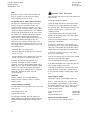
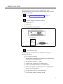
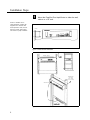
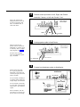
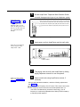
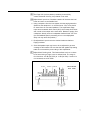
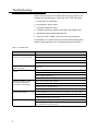
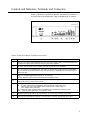
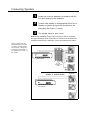
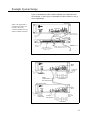
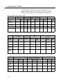
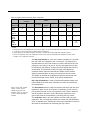
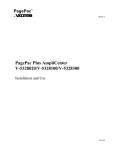
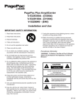
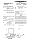
AT&T
®
PagePac Plus AmpliCenter
Installation and Use
Contents
General Information - 2
Before You Start - 3
Installation Steps - 4
Troubleshooting - 8
Controls and Indicators,
Terminals and Connectors - 9
Connecting Speakers - 10
Example System Setups - 11
Connectivity Chart - 12
Specifications - 14
AT&T 463-248-202
0II722051-300
Issue 3, Sept. 1994
Copyright © 1994 Harris Dracon
All Rights Reserved
Written/Printed in U.S.A.
Notice
Important Safety Information
Every effort was made to ensure that the information in this
guide was complete and accurate at the time of printing.
However, information is subject to change.
Always follow these basic safety precautions when installing and
using the system:
FCC Statement (Part 15) - Radio Frequency Interference
1. Read and understand all instructions.
The PagePac Plus AmpliCenter generates and uses radio
frequency energy and if not installed and used in strict
accordance with the manufacturer’s instructions, may cause
interference to radio and television reception. Testing is being
conducted for compliance with the limits for a Class B device in
accordance with the specifications in Part 15 of the FCC Rules
and Canadian D.O.C. regulations. This testing is designed to
provide reasonable protection against such interference.
However, there is no guarantee that interference will not occur
in a particular installation If this equipment does cause
interference to radio or television reception, which can be
determined by turning the AmpliCenter unit off and on, the user
is encouraged to try to correct the interference by one or more
of the following measures:
2. Follow all warnings and instructions marked on the product.
3. DO NOT block or cover the ventilation slots and openings.
They prevent the product from overheating. DO NOT place the
product in a separate enclosure or cabinet, unless proper
ventilation is provided.
4. Never spill liquid on the product or drop objects into the
ventilation slots and openings. Doing so may result in serious
damage to the components.
5. Repair or service must be performed by a factory authorized
repair facility or AT&T technician.
- Reorient the radio or TV receiving antenna.
6. The product is provided with a UL-CSA approved, 3-wire
ground type plug. This is a safety feature. DO NOT defeat the
safety purpose of the grounding type plug. DO NOT staple or
otherwise attach the AC power supply cord to building surfaces.
- Relocate the AmpliCenter unit with respect to the radio or TV
receiver or vice-versa.
7. DO NOT use the product near water or in a wet or damp
place (such as a wet basement).
- Plug the AmpliCenter unit into a different outlet so that it and
the radio or TV receiver are on different branch circuits.
8. DO NOT use extension cords. The product must be installed
within 6 feet of a grounded outlet receptacle.
If necessary, the user should consult the dealer or an
experienced radio/television technician for additional
suggestions. The user may find the following booklet, “How To
Identify and Resolve Radio-TV Interference Problems,” helpful.
This booklet was prepared by the Federal Communications
Commission (FCC) and is available from the U.S. Government
Printing Office, Washington, DC 20402. Stock order
No. 004-000-00345-4.
9. DO NOT install telephone wiring during a lightning storm.
Trademarks
PAGEPAC, PAGEPAC PLUS and AMPLICENTER are
trademarks of Harris Corporation. Centrex is a registered
trademark of AT&T.
Ordering and Reference Information
The order number for this book is 463-248-202. To order copies
of this book, call:
1-800-432-6600 in the U.S. and
1-800-255-1242 in Canada.
For related product information, refer to the PagePac Plus
System Installation and Configuration and Zone Expansion Unit
Installation and Use Manual for specific information on those
products.
2
10. DO NOT install telephone jacks in a wet location unless the
jack is specifally designed for wet locations.
11. Never touch uninsulated wires or terminals, unless the line
has been disconnected at the paging or controller interface.
12. Use caution when installing or modifying paging or control
lines.
Support Telephone Numbers
AT&T provides a toll-free customer Helpline 24 hours a day.
In the U.S., call the AT&T NTSC Group at 1-800-552-3293 or
the AT&T Helpline at 1-800-628-2888 if you need assistance
when installing, programming, or using your system. For service
or technical assistance in Canada, call one of the following
Technical Assistance Centers:
Eastern Canada and Ottawa:
Ontario:
Central and Western Canada:
1-800-363-1882
1-800-387-4268
1-800-663-9817
Domestic and International Approvals
UL813, FCC Part 15, Class A, CSA 950, and D.O.C.
Before You Start
Before installing your system, read and understand the safety
instructions. Be sure you have all the necessary parts, tools, and test
equipment, listed below.
1
Read Important Safety Information on Page 2
2
Check Shipping Container Contents
■
AmpliCenter Unit
■
Power Cord
■
This Installation and Use guide
AMPLICENTER D20, D100, D300
INSTALLATION MANUAL
AT&T
PagePac Plus
AmpliCenter
Installation and Use
POWER CORD
Figure 1. AmpliCenter Components
3
Have Required Tools
The following tools are required for the installation of the system
hardware and cabling.
■
No. 2 Phillips screwdriver
■
Standard blade screwdriver (1/4") and small, for terminal block
connections and level adjustments
■
Wire strippers (24 AWG - 12 AWG)
■
Telephone test set (optional, for troubleshooting)
■
Tone out circuit tester (optional, for troubleshooting)
■
Portable 70V speaker (use cabling pulled for ceiling speakers)
(optional, for troubleshooting)
■
Volt-Ohm Meter (optional, for troubleshooting)
■
Four # 8 wood screws, if mounting on wall
3
Installation Steps
1
NOTE: If installed next to
other equipment, including the
PagePac Plus Controller and
Zone Expansion Units, leave at
least four inches space above
and below for proper ventilation.
Mount the PagePac Plus AmpliCenter to either the wall,
cabinet or a 19" rack.
SIDE VIEW
AMPLICENTER
Figure 2. Wall Mounted Hardware
FRONT DETAIL
TYPICAL
COMBINATION
PAN HEAD
PILOT POINT
#10 - 32 (TYPICAL)
REAR DETAIL
POWER STRIP
Figure 3. Rack Mounted Hardware
4
2
Connect music input wires to Left, Right, and Ground
terminals, if stereo, or Left and Ground, if not.
70V OUT
NOTE: The optional audio
background music source can
be a CD or tape player, AM,
FM, or commerical radio, or
other audio device.
PAGE IN
MUSIC IN
AMPLICENTER
BACK PANEL
LOW FREQ
CUT-OFF
MONO
STEREO
Figure 4. Music Input Connections on AmpliCenter
3
Hookup speaker cable to AmpliCenter.
NOTE: If more than one
speaker cable is routed to the
AmpliCenter a connector block
is necessary. Refer to sample
wiring diagrams on page 10.
70V OUT
PAGE IN
MUSIC IN
AMPLICENTER
BACK PANEL
LOW FREQ
CUT-OFF
DO NOT hook up speaker
wires with AmpliCenter power
plug connected!
CABLE SHIELDING
TO SPEAKERS
Figure 5. Speaker Connection on AmpliCenter
4
Connect host telephone system to Amplicenter.
NOTE: Connect the 4-wire
RJ-11 type plug (used with
telephones) to the Page Input
connector (far right), or use the
Page In terminals.
Use Tip and Ring if installing to
an existing paging system (low
voltage output), VOX activated.
Use Tip and Ring if connecting
to a Loop Start or Ground Start
interface port in host telephone
system.
With a microphone, hook the
mic switch to C1 and Grd, and
the mic output to Tip and Ring.
Figure 6. Host Telephone System Connection
5
5
NOTE: Refer to the
Connectivity Chart on page 12
and 13 to determine the page
line output type of your
telephone system. In most
cases, the setting will be Loop
Start. You can also check with
your telecommunications
manager.
Set the AmpliCenter Telephone Mode Selection Switch
to match the page output type of your telephone system.
Used for input from paging port of Telephone System (PBX) or from Microphone
Used to parallel many AmpliCenter inputs without loading the source output
Input direct from Telephone System (PBX) with Ground Start Trunk Port
Input direct from Telephone System (PBX) with Loop Start Trunk Port
Figure 7. Telephone Mode Switch Setting
6
Insert power cord into AmpliCenter and into wall outlet.
NOTE: Do not use extension
cords or plug into locally,
“safety-fused” outlets.
6 FOOT
POWER CABLE
Figure 8. Power Cable
7
NOTE: If no page is heard,
refer to the Troubleshooting
Guidelines on page 8.
8
Test paging zone served by the AmpliCenter by dialing
paging telephone extension or use microphone.
Adjust sound levels using AmpliCenter controls, if
necessary.
Using a small standard screwdriver, make the following adjustments.
See Figure 9.
Adjust the Low Frequency Cut Off control. This control cuts out the
low frequency bass so that horns and small speakers are not
over-driven and distorted by excessive bass energy. Cut off
frequency is continuously adjustable from 50Hz (full CCW rotation)
to 400 Hz (full CW rotation).
6
The Page VOX (voice activation) sensitivity is turned fully
counter-clockwise if the Dry Loop feature is not used.
Adjust Music Input level. Clockwise rotation will increase the level.
Listen and set to a comfortable level.
4. Using a telephone from the host system, dial the paging extension.
Speak into the telephone in a normal manner. Your voice should
be heard from all connected speakers. The AmpliCenter Page
Input has an automatic level control (ALC) which keeps loud voices
and normal voices output at the same level. Beware of paging from
a telephone directly under a loudspeaker feedback howl can occur.
(An anti-feedback speech processing unit or a record/playback
delay unit may solve this problem.)
5. Re-adjust Music Input level to the desired loudness relative to
Paging loudness.
6. Some loudspeaker taps may have to be re-adjusted to get even
coverage at all locations. Be sure that the final speaker tap setting
totals do not exceed the power rating of the AmpliCenter.
Adjust Music Ducking level. This feature allows music to continue
to be heard during a Page, but at a reduced level. The range is
from less than –40 dB (full CCW) to –6 dB (full CW). If music-in is
not connected, set to full CCW.
70V OUT
PAGE IN
MUSIC IN
AMPLICENTER
BACK PANEL
LOW FREQ
CUT-OFF
Figure 9. Test Page Adjustments
7
Troubleshooting
Some common problems encountered when the paging system is not
operating are described below. Check each item in the order listed.
1. No AC power to AmpliCenter.
2. Host telephone system failure.
3. Host system page port failure.
4. A hardwire disconnect between host system and PagePac Plus.
5. AmpliCenter switch settings tampered with.
6. Volume low due to DTMF volume level not being set properly.
If the problem has not been resolved by checking the preceding items,
follow the steps described in the Troubleshooting table that follows.
Table 1. Troubleshooting
Corrective Action
Problem
When dialing the Page
extension, it does not answer
No power to AmpliCenter.
Host system not passing call through to AmpliCenter.
Telephone Mode Selection Switch not set correctly for host telephone system.
Ground start – Tip and Ring reversed or AmpliCenter not grounded.
Page extension answers, but
page is not heard
Audio signal not reaching speakers. Check wiring at AmpliCenter. Verify Page Accessed
LED is on.
Background music cannot be
heard
Input level not set correctly. Adjust music input level on AmpliCenter.
No power to music source. Verify power is on.
Radio off station. Adjust tuner.
Music input wires crossed, with signal grounded out.
Distorted, garbled, or raspy
sound from all speakers
connected to AmpliCenter
Short circuited speaker leads. Separate.
Music input level too high. Turn down.
Speaker transformer shorted. Replace.
Failed AmpliCenter. Return for repair.
Green power LED off
AC outlet receptacle is not live. Check outlet circuit breaker or use another outlet.
Power cord is loose.
Failed AmpliCenter. Return unit for repair.
Page access LED won’t go off
Page VOX too sensitive. Adjust.
C1 lead is grounded. If loop start or ground start, check that only 2 wires (Tip and Ring)
are connected by the modular plug cord.
8
Controls and Indicators, Terminals and Connectors
Figure 10 shows the controls and indicators, terminals and connectors on
the rear panel of the AmpliCenter. Table 2 identifies them by function.
AMPLICENTER
Figure 10. AmpliCenter Controls and Indicators, Terminals and Connectors
Table 2. Controls and Indicators, Terminals and Connectors
1.
AC Power in: 105 – 125 VAC, 210-250 VAC, 50/60 Hz, (voltage auto-selectable within unit)
2.
0dBm out, an auxiliary output that differs from the main 70.7V output in that it is a low level (0dB), 600
ohm balanced output used for driving a remote or off-premises amplifier
3.
DC Power, and 70V audio out to Controller (used only if Controller is also installed)
4.
Bass control screw-type adjustment pot. Attenuates low frequencies so that horns and small speakers
are not overdriven by excessive bass energy. Cut off frequency is adjustable from 50 Hz (full CCW) to
400 Hz (full CW)
5.
Music In: left and/or right channels with ground;
Paging In: redundant paging input (ground, C1, tip, and ring)
70V Out: Balanced output used for terminating the loudspeaker wiring
6.
Screw adjustable potentiometers: VOX sensitivity level, Music ducking (mute level for music during voice
page), Music level for various music sources
7.
LEDs: green – power on, lights when AC line voltage is applied to AmpliCenter.
red – overload, lights when the AmpliCenter output exceeds its output power rating.
This can occur when total speaker load is greater than the output rating, or
when speaker wiring is shorted.
red – unbalanced output, indicates when one speaker lead is accidentally shorted to ground.
green – page accessed, lights when voice paging is active.
8.
Telephone system mode switch: dry loop 600 ohms, dry loop Hi Z, ground start, or loop start
9.
Page input from host telephone system or Controller RJ11 connector: paging audio and control
9
Connecting Speakers
1
2
3
Locate and mount all speakers in accordance with the
floor plan drawing for this installation
Connect each speaker to the appropriate Home Run or
Speaker-to-speaker wiring scheme as shown on the
wiring plan (See Figure 11, below)
Test speaker wiring for short circuits
Measure the resistance of each home run wire run with an ohmmeter.
Any pair indicating a value of less than 15 ohms must be rechecked for
possible shorted wiring or speakers. Correct and problems and retest.
NOTE: If paging zones use
the talkback feature (available
only when used with PagePac
Plus Controller), cabling must
be shielded and grounded at
the AmpliCenter connector, not
the speaker.
HOME RUN METHOD
SPEAKERS
AMPLICENTER
66-TYPE
CONNECTION
BLOCK
SPEAKER TO SPEAKER METHOD
AMPLICENTER
Figure 11. Speaker Run Methods
10
SPEAKERS
Example System Setups
Figure 12 illustrates the interconnection between the AmpliCenter and
the Controller, if used. Figure 13 illustrates the interconnection of two or
more AmpliCenters.
AMPLICENTER
NOTE: If the AmpliCenter is
used with the PagePac Plus
Controller, refer to the
Controller Installation and Use
Guide for detailed instructions.
SET MODE SWITCH
TO DRY LOOP 600 OHM
POWER and 70V
AUDIO TO
CONTROLLER
CONTROLLER
RS-232 TO PC
(OPTIONAL)
ZONE CONNECTOR (1-8):
70V AUDIO OUT, AND CONTROL
SIGNAL IN or OUT.
POWER, CONTROL, and 70V AUDIO
to ZONE EXPANSION UNITS, lF ANY
INTERFACE TO
TELEPHONE SYSTEM
Figure 12. AmpliCenter Interface with PagePac Plus Controller
FIRST AMPLICENTER
MUSIC
INPUT
TO HOST TEL.
SYSTEM
(USE EITHER
METHOD)
AC POWER
CONNECTION
PAGING
CONNECTION
NEXT AMPLICENTER
TO SPEAKERS
NEXT AMPLICENTER
MUSIC
INPUT
AC POWER
CONNECTION
SET TO
DRY LOOP
600 W
TO NEXT
AMPLICENTER
TO SPEAKERS
Figure 13. Series AmpliCenters, without Controller
11
Connectivity Chart
The Connectivity chart gives the interface requirements for the host
telephone systems listed. This information is then used to set the
telephone mode function switch on the PagePac Plus AmpliCenter.
Table 3. PagePac Plus Connectivity Chart
Merlin Plus
Merlin 206/820
C.O. Line
Page
Port
C.O.
Line
Yes Note 1
–
Yes Note
1
–
–
–
–
Dry Loop (Hi Z)
–
–
Dry Loop (600 Ω)
–
Yes
Note 2 &
4
–
–
Set Mode
Switch to
Loop Start
Ground Start
3
Spirit 308/616
Merlin Legend
Merlin II
Merlin 1030/3070
Service
Module
C.O.
Line
Analog
Station
Yes Note 1
–
Yes Note 1
–
Yes
–
–
–
–
–
–
Yes
–
–
–
–
–
–
–
–
–
–
–
–
–
Page C.O. Line
Module
Yes
Note 2
&4
Spirit
1224/2448
Yes
Note 2 & 4
C.O. Line Analog
Station
Partnter II
Partner Plus
Partner
C.O. Line
Page Port
C.O. Line
C.O. Line
Analog
Station
C.O. Line
Analog
Station
Page
Port
Yes
–
Yes
Yes
–
Yes
–
Yes
Ground
Start 3
–
–
–
–
–
–
–
–
Dry Loop
(Hi Z)
–
–
–
–
–
–
–
–
Dry Loop
(600 Ω)
–
Yes
Note
2&4
–
–
–
–
–
Yes
Note 2
Set Mode
Switch to:
Loop
Start
System 25
System 85/G2
System 75/G1/G3I Definity
Set Mode
Switch to:
C.O. Line
Analog
Station
Aux. Port
C.O. Line
Analog
Station
Aux. Port
C.O. Line
Analog
Station
Aux.
Port
Loop Start
Yes
–
–
Yes
–
–
–
–
–
Ground
Start 3
Yes
–
–
Yes
–
–
Yes
–
–
Dry Loop
(Hi Z)
–
–
–
–
–
–
–
–
–
Dry Loop
(600 Ω)
–
–
Yes
Note 2
–
–
Yes
Note 2
–
–
Yes
Note 2
12
Table 3. PagePac Plus Connectivity Chart (Continued)
Comkey 416, 718, 1434
and 2152
Set Mode
Station to:
Dimension
Horizon
C.O. Line
Intercom
C.O. Line
Analog
Station
Intercom
C.O. Line
Analog
Station
Aux. Port
Yes
–
Yes
–
–
Yes
–
–
Ground
S t a r t3
–
–
Yes
–
–
Yes
–
–
Dry
Loop
(HI Z)
–
–
–
–
–
–
–
–
Dry
Loop
(600 Ω )
–
–
–
–
–
–
–
Yes
Note 2
Loop
Start
NOTES:
1.
2.
3.
4.
Pressing pound key twice (##) equals one pound key (#) to be sent to the AmpliCenter when dialing from a multi-button set.
A 2 pair RJ-11 cord must be used to interface with the AmpliCenter.
Ground Start trunk (for telephone system) must share a common ground with AmpliCenter page input ground.
Volume of AmpliCenter cannot be set/adusted via this access; adjust at AmpliCenter with standard touch-tone phone.
— Indicates a non applicable connection
The Dry Loop 600 Ohm is a four wire interface consisting of a dry audio
pair with a 600 ohm impedance and a control pair. The page input is
activated when the control pair receives a contact closure from the host
equipment, connecting C1 to ground. The Dry Loop page input can also
be activated by the presence of page input audio signals that exceed a
set threshold. This threshold is set by the page VOX adjustment;
clockwise rotation lowers the threshold and makes it more sensitive.
Adjust by experimentation to account for various line loss and noise.
This feature is beneficial for (amplified) microphone sources that don’t
have a Music/Page control contact, or for remote AmpliCenters.
Dry Loop Hi Impedance is used to interface with parallel multiple units.
Input impedance is 100K ohms. Otherwise, the same as the 600 ohm
dry loop operation.
NOTE: Ground start interface
requires common ground
between paging input and
telephone system by direct line
or other common grounding
methods.
The Ground Start mode is a two wire interface and has a 600 ohm input
impedance. When a trunk is accessed, a momentary ground is sent to
the ring-side of the pair by the host equipment, loop current is detected
and the tip-side of the pair is closed. Disconnect supervision of the
ground start mode is accomplished by monitoring the loop current.
The Loop Start mode is two wire interface and has a 600 ohm input
impedance. The host equipment draws loop current from the talk-battery
which is supplied by the AmpliCenter. Disconnect supervision of the loop
start mode is accomplished by monitoring the loop current.
13
Specifications
Table 4 describes the specifications of the AmpliCenter D20, D100, and
D300 models.
Table 4. AmpliCenter Specifications
Features
■
■
■
■
Telephone Paging Access: The AmpliCenter accepts inputs from telephone system (PBX) ground
start or loop start trunk ports, dry loop 600 ohm page ports, dry loop (hi Z), or amplified microphones.
Music interface: The AmpliCenter is the unit to which the background music source (CD, radio, tape
player) is connected, for distribution to the paging system.
Volume control: The AmpliCenter has music ducking (mute) level, music volume level, and bass
control adjustment pots on the rear panel. Overall output level can be controlled by dialing a DTMF
code.
Remote amplifier connection: The AmpliCenter provides 0 dBm audio output for connection to a
remote amplifier, which receives a contact closure control signal from the AmpliCenter.
■
D20: up to 20 Watts total speaker load, for a 70V constant voltage distribution system.
■
D100: up to 100 Watts, for a 70V constant voltage distribution system.
■
D300: up to 300 Watts, for a 70V constant voltage distribution system.
■
D20 and D100: 3-1/2" (8.9 cm) high x 19" (48.25 cm) wide x 5" (12.7 cm) deep.
■
D300: 3-1/2" (8.9 cm) high x 19" (48.25 cm) wide x 7.25" (18.4 cm) deep
Weight
■
D20: 5 lbs (11kg); D100: 6 lbs (13 kg); D300: q 7 lbs (14 kg)
Load Impedance
■
Minimum, D20: 250 ohms, D100: 50 ohms, D300: 16.7 ohms
Frequency
Response
■
60Hz to 16Khz
Total Harmonic
Distortion
■
Less than 1%, at rated power, 60 Hz to 16 kHz
Hum and Noise
■
Less than 80 dB below rated output, 20 Hz to 20 kHz bandwidth, unweighted
Telephone
Paging Access
■
Music Input
■
Sensitivity: 180 mV for rated output, single channel input. 90 mV with both inputs driven.
■
Impedance: 20 kohms, un-balanced, each input (left & right)
Overload
Protection
■
Current limiting, thermal shutdown, short circuit, reactive load, and internal DC fault protection.
Approvals
■
U.L. 813, C.S.A 950, NRTL/C
RJ-11 Jack
Specifications
■
Talk battery 24 volts, loop start or ground start, negative voltage ring lead
■
Impedence: 600Ω and 100KΩ
Temperature
Range:
■
0 to 40 deg. C. (32°F to 104°F) operational; to +50 deg. C. (122°F) with forced air
■
–20 to +70 deg. C. (28°F to 158°F) storage and shipment
Environmental
Requirements
■
Electrical, Power,
and Grounding
Requirements:
■
110-125 VAC, 57-63 HZ; or 220-240 VAC 47-53 Hz (automatic selection)
■
Outlet must be a 3-prong outlet, separate ground, not controlled by an on/off switch
■
D20: 1 amp max., D100: 2.5 amp/1.25 amp max., D300: 8 amp/ 4 amp max.
Rated Power
Dimensions
■
■
14
Automatic Level Control: 15:1 compression ration above -15dBm input; Gain Below Limiting Knee:
56dB; ALC Attack Time: Less than 3 msec.
Locate in an area free of excess moisture, corrosive gases, dust, and chemicals.
Humidty: 5% to 95% (non-condensing) storage/shipment and operation. Altitude: sea level to 10,000
ft. (1048 to 648 millibars) operational; 40,000 ft max. shipment.
A. Use the power cord supplied with the unit, or an equivalent cord that meets applicable safety
codes. Do not cut or remove the third wire ground prong.
B. The attachment-plug receptacles in the vicinity of the product or system are all to be of a
grounding type, and the grounding conductors serving these receptacles are to be connected to
earth ground at the service equipment.
1994 AT&T
All Rights Reserved
Printed in U.S.A.
AT&T 463-248-202
0II722051-300
Issue 3, Sept. 1994
Graphics © AT&T 1988