1
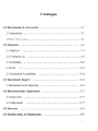
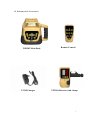
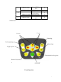
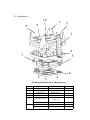
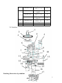
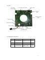
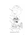
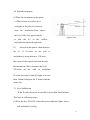
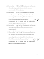
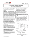
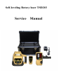
Self-leveling Rotary laser TSD203
Service
Manual
Catalogue
2
1.0 Instrument & Accessories
TSD203 Main Body
FC101Charger
Remote Control
TST100 Detector with clamp
3
Whole set of instrument includes TSD203、TST100 detector、
Clamp、FC101Charger and remote control
4 section 2# rechargeable batteries are available for the
instrument. Take the batteries out of instrument after .
loosing the cover screw of battery case.
1.1 Basic Operation
1. Press the Key On/Off, The laser head will rotate freely
to form a horizontal scanning-surface
of
laser
beam
as
reference surface, It also will emit a plump line upwards and
a down point when the instrument is set upright. When lay down
the laser, it will supply a plump plane and emit a horizontal
line .
2.According to the working requirement, The speed of spin
can be adjusted、stop rotate, laser head can step-move right
or left、scanning function、The slope of instrument can also
be adjusted. etc.
3.When the instrument match the detector FRD100,the height
of laser beam will be decided according to indicator of the
detector.
1.2 Key functions
⑴Voltage indicator:When the light is shining, The
The pressure of power is low. Should recharge instrument
4
Or renew the batteries(4 section 2# batteries)
⑵Power indicator:When it lights, the instrument is starting
Up. Otherwise it is closing down.
⑶Mode indicator:When it lights,the instrument is leveling
manually. When it winks, it stays in alam.(The slope of the
instrument is out of range)
⑷ON/OFF: Controlling the state of power
⑸ Speed up: Circling knob, Speed of scanning includes 5
levels:0-60-120-300-600 r.p.m
⑺ Manual/Automatic: Control the
mode
of
Manual
or
Auto
leveling.
⑻Left spinning: Making laser prism step-move anti-clockwise,
when
laser prism is stop spinning or in scanning mode.
⑼Right spinning: Make laser prism step-move clockwise, when
laser prism is stop spinning or in scanning mode.
⑽ X-axis: Adjusting the slope of X-axis, when the instrument
is in manual mode.
⑾ Y-axis: Adjusting the slope of Y-axis, when the instrument
is in manual mode.
⑿Key of Automatic drift system model: Warns the user for a
misaligned device.
5
2.0 Structure
TSD203-2-1001Shell set
TSD203-2-200 Underpan sets
TSD203-100 Pendulum
6
2.1Shell set
1
6
7
2
3
8
4
5
9
10
11
Bombing illustration of shell
Serial
1
2
3
4
5
6
7
8
Code
TSD203-203
TSD203-217
TSD203-202
TSD203-305
TSD203-212
TSD101-302
TSD203-214
TSD203-109
Name
Top-cover
Shielding glass
Shell
Panel
Label
Glass
Gasket
Screw
Quantity
1
1
1
1
1
1
1
1
7
9
GB/T845-1985
GB/T 96-1985
10
receive head
TSD101-315YB
11
Screw ST2.2
9.8
φ2.5 Gasket
Infrared
GB/T845-1985
Receive board
Screw ST2.2
4.5
4
4
4
1
4
2.2Shell set
Y-axis
X-axis
Scanning
Left-spinning
Speed-up
Right-spinn
Automatic drift system
Manual/Automati
c
ON/OFF
Penal function
8
2.3 Underpan set
10
9
8
1
2
3
4
7
5
6
Bombing illustration of underpan set
Serial
1
2
3
4
5
6
Code
TSD203-206
TSD203-205
TSD203-207
TSD203-201
GB/T818-2000
GB/T 96-1985
TSD203-215
TSD203-204
Name
Rubber-cover
Handle
Handle-cover
Base
Screw
M4 12
φ4Gasket
Spring Strip I
Battery cover
Quantity
1
1
1
1
1
1
2
1
9
GB/T845-1985
TSD203-208
7
GB/T845-1985
8
GB/T845-1985
9
TSD203-302
Screw
ST2.9 13.5
Battery
retainer
Screw
ST2.9 17.5
2#Rechargable
batteries
Screw
ST2.2 5.5
PCB
4
2
4
4
4
1
10
2.4 Pendulem
1
2
4
3
5
6
8
7
9
11
10
13
12
14
15
16
17
Bombing illustration of pendulum
10
Serial
Code
TSD101-307
1
2
3
4
TSD101-104
GB/T819.2-1997
TSD101-112
TSD101-107
TSD203-102
TSD101-110
TSD101-108
TSD101-124
TSD101-106
TSD202-116a
5
GB/T818-2000
GB/T818-2000
TSD203-209
TSD203-304
Name
Pentagon prism
10 10
Prism base
Screw 2.5 6
Raster
Scanning GearII
Scanning base
6801ZZ Bearing
Gasket I
Nut
Universal ring
Scanning gearI
Motor fixation
board
Motor
Screw
M1.6 4
Screw
M3 6
Scanning
optical coupler
base
Scanning
optical coupler
Quantity
1
1
3
1
1
1
2
1
1
1
1
1
2
2
2
2
board
6
Optical coupler
GB/T818-2000
GB/T845/1985
GB//T96-1985
TSD203-105
7
GB/T70.1-2000
GB/T80-2000
8
TSD203-104
GB309-85
GB/T80-2000
(Scanning)
Screw
M3 6
Screw
ST2.2 5.8
φ3 Gasket
Outer ring
Screw
M3 15
Screw
M2.5 3
Leveling
bracket
φ3 23.8 Pin
Screw
M3 6
2
2
2
2
1
4
2
1
2
11
GB/T80-2000
9
10
11
11
TXD441-124
TSD203-107
TSD203-211
P7-106
GB/T818-2000
TSD203-106
TXD441-124
12
GB/T80-2000
TSD203-108
P6-1-308
13
GB/T70.1-2000
GB//T96-1985
TXD441-106
14
GB/T70.1-2000
GB/T6170-2000
TSD201-134
15
TSD203-103
Screw
M3 8
Pin
Stabilizing
board
Alarm base
Alarm spring
Screw
2.5 6
Inner ring
Pin
Screw
M2.5 3
623ZZ Bearing
Spring holder
Spring(Long)
Screw
M3 8
φ3 Gasket
Leveling motor
set
Motor pillar
Screw
M3 24
M3 Nut
Sprin(Shorter)
623ZZBearing
Pendulum
6512Beam
4
2
1
1
1
2
1
2
2
2
1
2
1
1
2
1
1
2
2
2
1
1
16
17
GB/T80-2000
lamp-house(Top)
1526Beam
lamp-house
(Down)
Bubble set
Screw M3 8
1
1
6
12
2.5 PCB
X-leveling
motor socket
Y-leveling motor socket
Alarm socket
Scanning
socket
Scanning motor
socket
Up point socket
Down point socket
Power socket
Sensor socket
Charger socket
Infrared socket
Keyboard socket
2.6 Instrument Assembling
1
TSD203-2-100
2
GB/T845/1985
3
4
TSD203-100
FRE203-2-200
5
GB/T845/1985
Shell set
Screw
ST2.9 11.8
Pendulum
Underpan set
Screw
ST2.9 15.8
1
3
1
1
8
13
1
2
3
4
5
Bombing illustration of whole set
14
3.0 Instrument Inspect
(1)Place the instrument at the point
of 50m in front of wall(or set a
scaleplate at the point of 50m away
X1
X1-beam
h1
X2-beam
h2
from the instrument),Then adjust
the level of the base approximately
Approx.50m
to
aim
the
X1
to the wall(or
scaleplate)as depicted right side:
(1)
Switch on the power, then measure
the h1 of X1-beam on the wall or
scaleplate by using detector. (3)Loose
the screw of the tripod, then turn around
o
the instrument 180 to measure the h2 of
X2-beam on the wall or scaleplate.
D-value between h1 and h2 ought to be less
then 10mm (4)Inspect the Y-beam with the
same way.
3.1 Level calibration
If the D-value between h1 and h2 is more than 5mm,calibrat
The laser as following steps:
(1)Press the key ON/OFF, when the power indicator lights, Laser
will automatic leveling.
15
(2) Press the Key"
"and"
"simultaneously for 3 seconds
when undervoltage mode indicator winks, the instrument
enters the mode of Y-axis adjusting.
(3) Press the Key"
"or"
",the instrument will adjust one
step when press once. Check the position of laser beam when
undervoltage indicator is winking till the D-value between
h1 and h2 is less than 5mm.Then press the key"
" and "
"
simultaneously for 3 seconds until the undervoltage
indicator off, The calibration is accepted.
(4) Press the Key"
"and"
"simultaneously for 3 seconds
when undervoltage indicator winks, the instrument enters
mode of adjusting.
(5)Press the Key"
"or"
",the instrument will adjust one
step when press once. Check the position of laser beam when
undervoltage indicator is winking till the D-value between
h1 and h2 is less than 5mm.Then press the key"
" and "
simultaneously for 3 seconds until the undervoltage
indicator off, The calibration is accepted.
16
"
3.2 If the D-value of h1 and h2 is beyond 10mm, You should use
mechanical calibration, The method is as follows:
X1
Y2
Y1
X2
As illustration shows, When instrument is leveling, adjust X1
or X2(Y1 or Y2),until the D-value of h1 and h2 less then 5mm.
Attention: If the calibration is out of range, You should
better contact distributor for repairing.
17
4.0 Horizontal-line Adjust
4.1
Inspection
(1) Place the instrument between two walls with the distance
of 30m (or two scaleplates with the distance of 30m)
0.5m
Approx.30m
Approx. 30m
0.5m
(2) Place the instrument according to horizontal setting
manner and then adjust the instrument.
(3)Switch on the power, and then measure the middle point of
the laser beam on two walls(or scaleplates),There are hA、
hB and hA'、hB'
(4)
1=hA-hA′,
D-value between
2=hB-hB′
1 and
2 ought to be less than 4mm.
4.2 Adjusting(Vertical)
If D-value between Δ1and
Δ2 is more than 4mm ,adjust the
instrument in the same way of level adjusting. Please refer to
the details of Y-axis calibration in 3.0 and 3.1.
18
5.0 Detector
5.1 TST100: Introduce of the detector's circuit.
1. The laser beam is received by silicon photocell. After
amplifying and judging the signal received, the detector will
send out command signal to control the display of LCD and the
buzzer.
LCD illustration
States of buzzer:upward bias alarm、downward bias alarm、
19
accurate-orientated alarm(prolonged sound)
2.Normal fault and repair
(1)Buzzer doesn't work
① Symptons:Buzzer off when press key.
② Reason for causing this problem: a. Socket of buzzer
dropt。b. Broken of circuit board。
③ Repair: a. Open the cover then insert the socket.
b. Broken of circuit,send back to manufacturer.
(2)No response when power on.
①Symptoms:Press ON/OFF, there is no sound, no display on
LCD.
② Reason:
a. Wrong set of batteries. Socket on PCB has
dropt. c. Fault of circuit board.
③ Resolve method:
a. Open the batteries cover, then reset the batteries.
b. Open the shell, then insert the socket
c. Fault of circuit board,send back to manufacturer.
6.0 Malfunctions & Eliminations
6.1 Failures in starting up
(1) Symptoms:
After pressing the Key ON/OFF, power indicator can't light
and also the instrument doesn't start up.
20
(2) Causes:
a. Poor contact of keys on the panel or panel plug.
b.
Poor
contact
of
batteries
or
power
plug,
and
insufficient power,
c. Troubles of PCB.
(3) Eliminations:
a. Take off the shell,and renew the panel or connect the power
plug with PCB well.
b. Take down the cover of battery case to check whether t here
are some dirt or rust between the spring and spring strip,
and clear off them if it is
true;Recharge
then detach
the batteries till power is sufficient and
the shell to connect the power plug with PCB
well.
c. Detach the shell to change the PCB.
d. Please contact the supplier when the instrument still
doesn't start up after all your effort above.
6.2
No spinning of laser head.
(1) Symptoms:
The laser beam is being emitted but the laser head doesn't
rotate after instrument is power on.
(2) Causes:
21
a. Center to center distance of gear is not suitable,gearing
is abnormal.
b. Troubles of scanning motor.
c. Laser head has touched the optical coupler.
d. Troubles of PCB.
(3) Eliminations:
a. Take off the shell to readjust the center-to-center distance
of the gear.
b. Change the scanning motor after taking off the shell.
c. Detach the shell to readjust the space between laser head
and optical coupler.
d. Change the PCB.
22