1
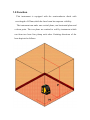
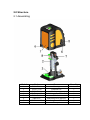
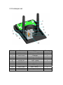
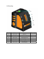
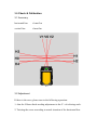
Cross line laser EK-117
Service manual
Suzhou Fukuda Laser Precision Instrument Co.,Ltd
Catalogue
1.0 Function 。
。。
。。。
。。。
。。。
。。
。。。
。。。
。。
。。。
。。。
。。
。。。
。。。
。。
。。。
。。
(1)
2.0 Structure
。
。。。
。。。
。。。
。。
。。。
。。。
。。
。。。
。。。
。。
。。。
。。。
。。
。。。
。。。(2)
2.1Assembling
。。。
。。
。。。
。。。
。。
。。。
。。。
。。
。。。
。。。
。。
。。。
。(2)
。
。
。
。。。
2.2Pendulum set 。。。
。。。
。。。
。。
。。。
。。。
。。
。。。
。。。
。。
。。。
。。。
。。
。。。
。(2)
。。
。。。
。。。
。。
。。。
。。。
。。
。。。
(4)
2.3 Underpan set 。。。
。。。
。。。
。。
。。。
。。。
2.4 Housing 。。
。。。
。。。
。。
。。。
。。。
。。
。。。
。。。
。。
。。。
。。。
。。
。。。
。。。(6)
3.0 Check & Calibration。
。
。
。。
。。。
。。。
。。
。。。
。。。
。。
。。。
。。。
。。
。。。
。。
(8)
3.1 Accuracy。
。
。。
。。
。。。
。。。
。。
。。。
。。。
。。
。。。
。。。
。。
。。。
。。。
。。
。。。
。(8)
3.2 Adjustment。
。。
。。
。。。
。。。
。。
。。。
。。。
。。
。。。
。。。
。。
。。。
。。。
。。
。。。
(8)
。。
。。。
。。。
。。。
。。
。。。
。。。
。。
。。。
。
(10)
4.0 Malfunctions & Eliminations 。
5.0Technology parameter。。。。
。。。
。。。
。。
。。。
。。。
。。
。。。
。。。
。。
。。。
。。
(13)
1.0 Function
This instrument is equipped with the semiconductor diode with
wavelength of 635nm,which the laser beam has supreme visibility.
The instrument can make one vertical plane, one horizontal plane and
a down point. The two plane are emitted to wall by instrument which
can form two laser line plump each other. Emitting directions of the
laser depicted as follows:
2.0 Structure
2.1 Assembling
Serial
1
2
3
4
5
6
7
8
Code
FLG117-300
FLG117-100
FLG117-200
GB/T846-1985
FLG117-011
GB819-85
GB/T846-1985
Name
Housing
Pendulum set
Underpan set
Stabilizing screw ST2.9×5.5
Knob
Stabilizing screw M2X16
Stabilizing screw ST2.2×13
Alarm pan
Quantity
1
1
1
3
1
1
1
3
2.2 Pendulum set
Serial
1
2
3
4
5
6
7
8
9
10
11
12
13
Code
LV288-033
693
FLG117-010
FLG117-002
FLG117-003
FLG117-009
GB309-84
GB309-84
766
FLG117-001
538K
Name
Cover ring
ф3×ф8×3 Bearing
Long cover
Settled device
Universal ring
Short cover
pin 3X19.8G3
pin 3X23.8G3
Alarm pan
Alarm board
vertical light
Pendulum
horizontal light
Quantity
4
4
1
1
1
1
1
1
1
1
1
2.3 Underpan set
Serial
1
2
3
4
5
6
7
8
9
10
11
12
Code
GB/T846-1985
FLG117-016
LV188-110
FLG117-006
FLG117-005
GB894.2-86
FLG117-008
GB819-85
FLG117-007
Name
PCB
Stabilizing screw ST2.9×5.5
Underpan
Magneticф8×5
Stabilizing screw M2.5×8
Lock Spring
Main Pole
Spindle
B Bar ring
Lock device . .
Stabilizing screw M2.5X6
centre rod
Quantity
1
3
1
4
1
1
1
1
1
3
1
2.4 Housing
Serial
1
2
3
4
5
6
7
8
Code
FLG117-021
Keyboard
Name
FLG117-012
FLG117-019
FLG117-017
FLG117-015
FLG117-020
FLG117-018
∮12mm bubble
rubber overall
Vertical glass Label
Vertical glass
Housing
Horizontal glass Label
Horizontal glass
Quantity
1
1
1
1
1
1
1
1
3.0 Check & Calibration
3.1 Accuracy
horizontal line
±1mm/5m
vertical line
±1mm/5m
3-1
3.2 Adjustment
If there is the error, please turn to the following operation:
1. Aim the H laser diode needing adjustment to the Y+ of referring scale.
2. Twisting the screw according to actual situation of the horizontal line.
3-2
3-3
(1). If the adjusting line H is the H1, loosen the screw2, then tighten the
screw 1(3—2、3—3), If is the H2, loosen the screw1, then tighten the
screw 2, repeat the operation until H line matches the referring H0
line。
(2). If the adjusting line H is the H3, loosen the screw3, then tighten the
screw 4(3—2、3—3), If is the H4, loosen the screw4, then tighten the
screw 3, repeat the operation until H line matches the referring H0
line。
(3). If H laser departure from the referring VO line or the accuracy error
exists between near point and far point, repeat the step1and step2 until
the H line matches Ho line.
II.V laser calibration
1. Aim the H laser diode needing adjustment to the Y+ of referring scale.
2. Twisting the screw according to actual situation of the horizontal line.
(1). If which adjust line is the V1, loosen the screw5, then tighten the
screw 5. (3—2、3—3). If which adjust line is the V2, loosen the
screw6, then tighten the screw 5, repeat the operation until V line
matches the referring VO line.
4.0 Malfunctions & Eliminations
4.1Failure in switching on the instrument
Causes:
⑴The voltage power of 3 section dry batteries is less than 3.
⑵Problem of power plug’s(2 socket) connect with the main PCB
⑶Problem of panel plug’s(9 socket)connect with the main PCB
Elimination:
⑴Renew the batteries
⑵Take off the Housing and reconnect the power plug with main PCB.
⑶Take off the housing then reconnect the panel plug with main PCB
Attention: If the there is a damage with panel or Main PCB, It may also
cause the same problem(The rate is rare), In that case, Please contact
manufacturer and look for more service.
4.2 No laser emit after instrument start to work
Cause:
⑴The slope of the instrument exceeds the leveling range and instrument
stays in self-alarm.
⑵The connection between diode and main PCB has some errors.
Elimination:
⑴Adjust the leg screw to make the instrument back into the leveling
situation.
⑵Take off the housing then reconnect the diode to socket of PCB.
Attention: It will also cause the problem of no laser emitting(Possibility is
rare) if there is a damage of PCB or diode. In that case, Please contact
manufacturer and look for more service.
4.3Failure in leveling after the laser switch on.
Causes:
⑴There is a rustiness caused by oxygenation on bearing surface.
⑵Poor connection with the self-alarm ring due to the oxygenation of it’s
surface.
Elimination:
⑴Take off the housing, change the rusted bearing.
⑵Take off the housing, then take out the pendulum, clean the self-alarm
ring with pure ethanol.
5.0 Specification
Line: one horizontal line; one vertical line;
Accuracy: ±1mm/5m
Self leveling range:Approx. ±3°
Working range: Approx. 10m(indoor).Approx. 50m(with detector);
Laser wavelength: Laser Diode: 635nm×2
Working temperature:
Power:
Operation time :
Measurement:
Weight:
-10℃--+45℃(-14oF--+113oF)
DC 3V (2section of 5# dry betteries)
Approx.6 hours
85×67×102mm
0.5kg