1
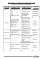
Flammable Vapor Ignition Resistant
Water Heaters
SERVICE
MANUAL
Troubleshooting Guide
and Instructions for Service
(To be performed ONLY by
qualified service providers)
Models Covered
by This Manual:
LG250H65*(N,X)
RG230S*(N,X)
RG230T*(N,X)
RG240S*(N,X)
RG240T*(N,X)
RG250H*(N,X)
RG250L*(N,X)
RG250S*(N,X)
RG250T*(N,X)
(*) Denotes Warranty Years
Manual 238-51542-00A REV 4/15
Save this manual for future reference
The Bradford White
®
Page Service Procedure
Introduction
3
---
Troubleshooting Chart
4
---
Inner Door Gasket Removal, Inspection, and Replacement
7
RG-I
Thermocouple/Thermopile Testing and Replacement
10
RG-II
Pilot Assembly Inspection Cleaning and Replacement
13
RG-III
Piezo Igniter, Electrode Testing and Replacement
14
RG-IV
White Rodgers Gas Valve Testing and Replacement
15
RG-V
Honeywell Gas Control Testing, Disassembly, and Replacement
20
RG-VI
Burner Operation Inspection, Adjustment, Cleaning and Replacement
31
RG-VII
Resettable Thermal Switch Testing and Replacement
34
RG-VIII
ScreenLok® Flame Arrestor Cleaning
36
RG-IV
DipTube and Anode Inspection and Replacement
37
RG-X
Generic Parts List
39
---
2
2
INTRODUCTION
The Bradford White DEFENDER Safety System®
The Bradford White DEFENDER Safety System® was designed to resist the ignition
of flammable vapors that can occur outside of the water heater. Use and installation
are nearly identical to previous versions of atmospherically fired and vented water
heaters. A number of exclusive design features are incorporated in the system that
will require additional knowledge on the part of the qualified service provider. The
following information will instruct service professionals on the function, proper
diagnosis and repair of water heaters employing the Bradford White DEFENDER
Safety System.
How the Safety System Works
During normal operation, air for combustion is drawn into the water heater through the
opening in the jacket. This air travels down and around the combustion chamber and
enters through holes in the very bottom of the corrosion-resistant combustion
chamber. The air then travels up through the oriented flame arrestor plate louvers,
where the velocity of the air is increased and its direction altered. The air then mixes
in a normal manner with the supplied gas and is efficiently combusted, producing very
low NOx emissions.
In the case where trace amounts of flammable vapors are present in the air flowing
into the combustion chamber, the vapors are harmlessly ignited by the burner / pilot
flame. If flammable vapors are in sufficient quantity to prevent normal combustion,
the burner/pilot flame is shut down.
Should the flammable vapors continue to the burner, the flame arrestor plate prevents
the flames from traveling backwards and igniting vapors outside of the combustion
chamber. The calibrated, multipurpose thermal switch recognizes this and shuts
down the pilot and main burner. This switch also deactivates the burner and pilot in
the unlikely event of restricted airflow caused by severe lint, dust or oil accumulation
on the arrestor plate.
3
3
White Rodgers Gas Valve Troubleshooting Chart
Flammable Vapor Ignition Resistant Water Heaters
SYMPTOM
Pilot will not light
Pilot will not
stay lit
when button is released
Pilot will light but the main
burner will not come on
PROBABLE CAUSE
1. No incoming gas or too low gas
pressure.
2. Gas control knob set to wrong
position.
3. Pilot light button not being fully
depressed when attempting to light
pilot.
4. Pilot orifice or pilot tube is obstructed
or kinked.
5. Pilot electrode not sparking to pilot.
6. Piezo igniter not functioning.
1. Turn on gas supply and/or check line
pressure.
2. Review lighting instruction. Set
combination/thermostat gas valve to
correct position.
3. Review lighting instruction. Fully
depress pilot lighting button.
4. Clean, repair or replace.
5. Verify correct electrode position.
Replace pilot assembly.
6. Replace piezo igniter.
1. Poor thermocouple connection at
combination thermostat/gas valve.
2. Thermocouple not fully engaged in
pilot assembly bracket.
3. Pilot flame is not fully enveloping the
thermocouple “hot” junction.
4. Weak or defective thermocouple.
5. Open ECO on combination
thermostat/ gas valve.
6. Defective magnet in combination
thermostat/gas valve.
7. Resettable thermal switch has
opened.
1. Check connection at combination
thermostat/gas valve. Proper
tightness should be finger tight plus ¼
turn.
2. Inspect thermocouple to ensure that it
is fully engaged into pilot bracket.
3. Adjust tip of thermocouple to be fully
engulfed by pilot flame.
4. Check thermocouple and replace if
necessary.
5. Check ECO continuity and replace
combination thermostat/gas valve if
necessary.
6. Check magnet operation and replace
combination thermostat/gas valve if
necessary.
7. Determine cause of switch activation.
To reset, depress button on resettable
thermal switch located on inner door.
1. Combination thermostat/gas valve set too
low for desired water temperature.
2. Combination thermostat/gas valve
temperature is satisfied.
3. Insufficient gas supply or low gas
pressure.
4. Combination thermostat/gas valve has
wide differential or is out of calibration.
1. Adjust temperature dial on combination
thermostat/gas valve.
2. Check temperature dial setting on
combination thermostat/gas valve.
3. Check gas supply and line pressure.
4. Check combination thermostat/gas valve
for proper operation, replace if
necessary.
1. Insufficient combustion air supply.
Pilot goes out periodically
(after heating cycles, once
a day, once a week etc.)
2. Incorrect, clogged vent system/ vent
terminal or location.
3. Inconsistent gas supply or gas pressure.
Not enough hot water
CORRECTIVE ACTION
1. Combination thermostat/gas valve set too
low for desired water temperature.
2. Cold inlet water temperature is very cold.
3. High demand periods.
4. Incorrectly sized water heater for
application.
5. Combination thermostat/gas valve is out
of calibration/not functioning.
6. Out of spec dip tube is diluting hot water
with cold water.
1. Verify adequate combustion air is available
to the unit. Check and clear Jacket slot
openings of any dirt, dust, restrictions or
other obstructions. Inspect flame arrestor
plate and clean with stiff bristled brush
and/or vacuum to remove any debris
accumulation.
2. Check venting for proper sizing and proper
operation
3. Check gas supply and line pressure.
1. Check dial on combination thermostat/gas
valve.
2.Extremely cold water going into the heater
will decrease the amount of hot water
produced. It may be necessary to temper
incoming water supply.
3. Adjust high demand usage.
4. Contact Plumbing professional.
5. Check combination thermostat/gas valve
for proper operation, replace if
necessary.
6. Inspect dip tube and replace if necessary.
4
4
SERVICE
PROCEDURE
1. See Service Procedure
RG-V, Page 12.
4. See Service Procedure
RG-III, Page 10.
5. See Service Procedure
RG-III, Page 10.
6. See Service Procedure
RG-IV, Page 11.
4. See Service Procedure
RG-II, Page 8.
5. See Service Procedure
RG-V, Page 14.
6. See Service Procedure
RG-V, Page 13.
2. See Installation &
operation manual.
3. See Service Procedure
RG-V, Page 12.
4. See Service Procedure
RG-V, Page 12.
1. See Service Procedure
RG-VIII, Page 22.
3. See Service Procedure
RG-V, Page 12.
5. See Service Procedure
RG-V, Page 12.
6. See Service Procedure
RG-IX, Page 23.
Honeywell Gas Control Troubleshooting Chart
Flammable Vapor Ignition Resistant Water Heaters
Observe green LED indicator on Gas
Control. Error flash codes are displayed with
a three second pause before repeating.
Check and repair the system as noted in the
troubleshooting table below.
LED Status
Green LED Indicator
Control Status
Probable Cause
Service
Procedure
None (LED not on or
flashing.
Gas control is operating normally.
Pilot flame may not be present.
Check for pilot flame through sight
glass and light if necessary.
1. Gas control is functioning
normally.
2. Gas control is not powered. Light
pilot.
3. Thermopile failure.
If the pilot will not stay
lit replace pilot
assembly. If problem
persists replace gas
control.
One flash and three
second pause
If set point knob is in “PILOT”
position then pilot flame is
detected. Turn set point knob to
desired setting.
Gas control is powered and waiting
for the set point knob to be turned to
a water temperature setting.
Normal operation.
Adjust thermostat to
desired temperature
setting.
LED on continuously
(Solid)
Set point knob has been recently
turned to the “OFF” position. Wait
until LED goes out before
attempting to relight.
Set point knob was turned to “OFF”
position.
LED will go out and the
control will function
normally when the pilot
is lit.
1. Thermopile failure.
2. Unstable pilot.
3. Pilot tube block or restricted.
4. Resettable thermal switch has
opened.
1. See service
procedure RG-II
2. See service
procedure RG-III
3. See service
procedure RG-III
4. See service
procedure RG-VIII
Weak pilot signal detected. System
Two flashes and three
will reset when pilot flame is
second pause
sufficient.
Three flashes and
three second pause
Insufficient water heating. System
will reset.
1. Temperature sensor out of
calibration.
1. See service
procedure RG-VI
Four flashes and
three second pause
Excessive tank temperature.
System must be reset.
1. Temperature sensor out of
calibration.
2. Faulty gas control.
1. See service
procedure RG-VI
2. See service
procedure RG-VI
5
5
Honeywell Gas Control Troubleshooting Chart
Flammable Vapor Ignition Resistant Water Heaters
Observe green LED indicator on Gas
Control. Error flash codes are displayed with
a three second pause before repeating.
Check and repair the system as noted in the
troubleshooting table below.
LED Status
Green LED Indicator
Control Status
Five flashes and three
Thermostat/well sensor fault.
second pause
Probable Cause
1. Damage to the temperature
sensor.
2. Temperature sensor resistance
out of range.
1. See service
procedure RG-VI.
Six flashes and three
second pause
Water leak detected by accessory
module.
Excessive amount of water in drain
pan/water dam.
1. Check T&P valve.
2. Check all water
fittings.
3. Pressurize and leak
test tank.
Seven flashes and
three second pause
Gas Control electronic fault
detected.
1. Control needs to be reset.
2. Control is wet or physically
damaged.
1. Reset gas control
2. Replace gas
control.
Eight flashes and
three second pause
Standing pilot remains on while set
point knob is in “OFF” position.
Pilot valve stuck in open position.
Replace gas control.
6
6
Service
Procedure
SERVICE PROCEDURE RG-I
Inner Door/Gasket Removal,
Inspection, and Replacement
Inner Door Removal Procedure
Step 1.
Rotate knob of the combination
thermostat/gas valve to the “OFF” position.
Step 2.
Remove outer jacket burner access door.
Step 3.
Inner Door Removal.
For Honeywell Control, rotate
knob counter-clockwise to the
“OFF” position.
a) Disconnect resettable thermal switch wire leads
(leading from gas control/gas valve).
b) Remove (2) hex drive screws from right side inner door.
c) Remove (2) hex drive screws from flange section of inner door.
d) Remove (2) hex drive screws from left side inner door.
e) Remove inner door and inspect per step 4.
For White Rodgers Control,
depress knob slightly and rotate
clockwise to the “OFF” position.
Resettable Thermal Switch
Wire Connection
Hex Drive Screws
Right and Left Side Inner Door
Hex Drive Screws at
Flange Area of Inner Door
Step 4.
Fully inspect inner door gaskets for the following:
>Tears
>Missing material
>Cracks
>Dirt or debris
>Other imperfections that will inhibit proper seal
>Gasket adhesion to inner door
>Material left on combustion chamber (around opening)
If the gasket is not affected by any of the above, gasket replacement is not required. If replacement
is required, proceed to Inner Door Gasket Replacement Procedure.
Inner Door Gasket Replacement Procedure
GASKET OVERLAP
MUST BE AS
SHOWN ±1/32"
RECOMMENDED
PATTERN FOR RTV
SEALANT
PLACE FLANGE
SECTIONS FIRST
ENLARGED
VIEW OF
FLANGE AREA
VIEW WITH
GASKETS IN
PLACE
EXPANDED
VIEW
7
7
SERVICE PROCEDURE RG-I
Inner Door/Gasket Removal,
Inspection, and Replacement
Installation of Inner Door With Gasket
Step 7.
Step 8.
Step 9.
Clean any residual gasket residue or other
debris from combustion chamber surface
before installing the inner door/gasket
assembly.
Place the left side inner door into position
first. Firmly position the radiused channel of
the inner door around the feedline. Using the
(2) hex drive screws from step 3d, secure left
side inner door in place
DO NOT OVER TIGHTEN SCREWS.
Position thermocouple, pilot tube and Piezo
wire against left side inner door flange gasket.
DO NOT ROUTE THROUGH RADIUSED
CHANNEL WITH FEEDLINE.
WARNING
Stripped fastener connections may allow
for seal breach of inner door. A seal
breach may result in a fire or explosion
causing property damage, personal injury
or death. Do not over tighten screws in
steps 8, 10 and 11.
If a fastener connection is stripped,
contact the manufacturer listed on the
water heater rating plate.
Position thermocouple/thermopile,
pilot tube and piezo wire.
Radiused Channel for
Feedline
8
8
SERVICE PROCEDURE RG-I
Inner Door/Gasket Removal, Inspection
Replacement and Reinstallation
Step 10. Firmly place right side inner door flange against the left side inner door flange and secure with (2)
hex drive screws from step 3c. DO NOT OVER TIGHTEN SCREWS.
Step 11. Align right side inner door to combustion chamber and verify the fastener holes of the combustion
chamber are aligned with the right side inner door slotted opening. Verify seal integrity around
combustion opening. Secure right side inner door using (2) hex drive screws from step 3b.
DO NOT OVER TIGHTEN SCREWS. Verify both left and right sides of the inner door are properly
positioned and sealed against the combustion chamber.
Secure flange with
hex drive screws.
Verify threaded hole
alignment with slotted
openings in inner door.
Step 12. Reconnect lead wires from combination thermostat/gas valve to resettable thermal switch (See
photo in step 3). Note, wire terminations are interchangeable with either resettable thermal switch
connections.
Step 13. Replace outer jacket burner access door.
Step 14. To resume operation follow the instructions located on the lighting instruction label or the lighting
instructions located in the installation and operation manual.
9
9
SERVICE PROCEDURE RG-II
Thermocouple/Thermopile Testing and
Replacement
CLOSED CIRCUIT THERMOCOUPLE TESTING (White Rodgers Control)
Step 1.
Closed circuit testing is the preferred method for testing thermocouple. Following the lighting
instruction label on the heater, proceed to light the pilot and allow to operate for three minutes. If
the pilot will not stay lit, hold the pilot button (located on the combination thermostat/gas valve)
down during this test.
Step 2.
Using a multimeter capable of measuring millivolts, connect one lead
using an alligator clip to the copper sheath of the thermocouple, use the second lead of the
multimeter to probe the top terminal located at the back of the combination thermostat/gas valve.
Step 3.
If meter reads 10 mv or higher, the thermocouple is OK. If reading is below 10 mv,
replace the thermocouple.
Probe top terminal on
back of combination
thermostat/gas valve
Alligator clip to copper
sheath of thermocouple
CLOSED CIRCUIT THERMOCOUPLE TESTING (Robertshaw Control)
Step 1.
Disconnect thermocouple from combination thermostat/gas valve.
Step 2.
Connect a thermocouple adaptor
(BWC P/N 239-44642-00, Robertshaw P/N 75036) at the
thermocouple location in the combination thermostat/gas valve.
Step 3.
Reconnect thermocouple to adaptor. Make certain all
connections are tight (finger tight plus ¼ turn).
Step 4
Using a multimeter capable of measuring millivolts, connect
one alligator clip to the set screw of the adaptor, and the other
alligator clip to copper portion of the thermocouple.
Step 5.
Following the lighting instruction label on the heater, proceed to light the pilot and allow to operate
for three minuets. If the pilot will not stay lit, hold the red reset button (located on the combination
thermostat/gas valve) down during this test.
Step 6.
If meter reads 13 mv or higher, the thermocouple is OK. If reading is below 13 mv
replace the thermocouple.
10
10
SERVICE PROCEDURE RG-II
Thermocouple/Thermopile Testing and
Replacement
OPEN CIRCUIT THERMOCOUPLE TESTING (White Rodgers Gas Valve)
Step 1.
Disconnect thermocouple from combination thermostat/gas valve.
Step 2.
Using a multimeter capable of measuring millivolts, connect
one alligator clip to the end ball or contact portion of the
thermocouple, and the other alligator clip to copper portion of
the thermocouple.
Step 3.
Following the lighting instruction label on the heater, proceed to light the pilot and allow to operate
for three minutes. It will be necessary to hold the pilot button down continuously throughout
this test. A reading of 20 to 30 millivolts indicates good thermocouple output.
THERMOCOUPLE REPLACEMENT (White Rodgers Gas Valve)
Step 1.
Turn off gas supply to water heater. Rotate knob of combination
thermostat/gas valve to “OFF” position.
Depress knob slightly and rotate
clockwise to the “OFF” position.
Step 2.
Remove outer jacket door.
Step 3.
Remove right side of inner door per SERVICE PROCEDURE RG-I, steps 3a through 3c.
Step 4
Disconnect thermocouple from combination thermostat/gas valve. Locate other end of
thermocouple inside of combustion chamber and remove from pilot bracket. Pull firmly pulling away
from the pilot assembly.
Step 5.
Install new thermocouple into pilot bracket making certain the thermocouple is fully engaged into
the pilot bracket. Position thermocouple against left side inner door flange at its original position.
Connect other end of thermocouple to combination thermostat/gas valve (finger tight + ¼ turn).
Step 6.
Inspect inner door gasket per
SERVICE PROCEDURE RG-I, Step 4.
Step 7.
Install right side inner door per
SERVICE PROCEDURE RG-I,
Step 10 through Step 13.
Step 8.
To resume operation follow the instructions located on the lighting instruction label or the lighting
instructions located in the installation and operation manual.
Thermocouple position
11
11
SERVICE PROCEDURE RG-II
Thermocouple/Thermopile Testing and
Replacement
OPEN CIRCUIT THERMOPILE TESTING (Honeywell Gas Control)
The following test should be performed while the pilot flame is on.
Step 1.
Turn knob to pilot position and depress.
Step 2.
Continue pressing knob and remove red (+) wire from resettable thermal door switch.
Step 3.
Using a multimeter capable of measuring millivolts, connect the positive side of the multimeter to
the terminal of the resettable thermal door switch. Connect the negative side of the multimeter to
any earth ground location (jacket base, screw, etc.).
Resettable Thermal Door
Switch Terminal (+)
Jacket Base Screw (-)
Normal thermopile operation will be between 350mV - 850mV. If reading is less than 350mV, replacement of
pilot assembly is recommended following SERVICE PROCEDURE RG-III.
Step 4.
If thermopile reading is between 350mV - 850mV, remove multimeter and reconnect red wire to
positive (+) terminal of gas control.
Step 5.
Release gas control knob and turn to desired setting to resume normal operation.
12
12
SERVICE PROCEDURE RG-III
Pilot Assembly Inspection, Cleaning
and Replacement
PILOT/ELECTRODE ASSEMBLY INSPECTION, CLEANING AND REPLACEMENT
Step 1.
Turn off gas supply to water heater. Rotate knob
of gas control/gas valve
to “OFF” position.
Step 2.
Remove outer jacket door.
Step 3.
Remove right side of inner door per
SERVICE PROCEDURE RG-I, steps 3a through 3c.
Step 4
Disconnect thermocouple/thermopile, pilot tube,
and feedline from gas control/gas valve.
For Honeywell Control, rotate
knob counter-clockwise to the
“OFF” position.
For White Rodgers Control,
depress knob slightly and rotate
clockwise to the “OFF” position.
NOTE: Feedline nut for natural gas control
uses right hand threads, LP control uses left hand thread.
Step 5
Disconnect piezo ignition wire from piezo igniter.
Step 6.
Remove burner assembly from combustion chamber.
Step 7.
Remove pilot/electrode assembly from feedline.
Step 8.
Inspect pilot for the following:
Feedline Nut
a) Primary air openings for blockage. Must be free from any
debris (dirt, lint, etc).
b) Kinks or cracks in the pilot tube. If found,
the pilot must be replaced.
Step 9.
Inspect pilot orifice:
Primary Air
Opening
a) Remove ½" nut from bottom of pilot assembly.
b) Remove pilot tube and pilot orifice.
c) Inspect pilot orifice for blockage, must be cleaned
or replaced. (Honeywell pilot orifice not replaceable,
replace pilot assembly)
Pilot Orifice
Step 10. Install pilot/electrode assembly to feedline, secure with screw from step 7.
Step 11. Re-Install burner assembly into combustion chamber, connect feedline,
pilot tube and thermocouple/thermopile to gas conrol/gas valve.
Step 12. Install inner door per SERVICE PROCEDURE RG-I, step 4 through 13.
Step 13. To resume operation follow the instructions located on the lighting
instruction label or the lighting instructions located in the installation
and operation manual.
Removal of thermopile from
Honeywell pilot assembly is not
recommended, but can be
achieved by viewing the pilot
assembly from the top and
pressing the thermopile towards
the right while pulling to remove.
13
13
SERVICE PROCEDURE RG-IV
Piezo Igniter, Electrode Testing
and Replacement
PIEZO IGNITER, ELECTRODE TESTING AND REPLACEMENT
With the pilot not in operation (no pilot flame) you can check the piezo and electrode circuit by viewing pilot
thru the sight glass located on the inner door and observing the spark action.
Step 1.
Remove outer jacket door.
Step 2.
Repeatedly depress the piezo igniter while viewing the pilot thru the sight glass. If a
spark is present, the circuit is OK. If there is no spark, proceed to step 3.
View spark
action through
sight glass
Repeatedly
Depress Piezo
Igniter
Step 3.
Remove orange (or white) wire from Piezo igniter and install a jumper wire in its place.
Hold the other end of the jumper by the wire insulation or using an insulated tool, next to
an unpainted surface such as the feedline or gas valve and depress the piezo igniter. If
there is a spark, the igniter is OK, the pilot is not functioning and must be replaced, see
SERVICE PROCEDURE RG-III for pilot replacement. If no spark is present the igniter is
not functioning and must be replaced.
Step 4a. For White Rodgers gas valves: With orange wire disconnected from piezo igniter. Using
a common screw driver, place blade of screw driver under piezo bracket and gently pry
bracket from front of gas valve and unhook bracket from rear of gas valve.
Common Screw
Driver
Step 4b. For Honeywell gas controls: To replace igniter, see “Gas Control Disassembly
Reassembly” in SERVICE PROCEDURE RG-VI.
14
14
SERVICE PROCEDURE RG-V
Gas Valve Testing and Replacement (White
Rodgers/Robertshaw)
Gas Valve Testing and Replacement (White Rodgers)
The gas valve is a non repairable device. If trouble shooting has determined a problem with the gas valve, it
must be replaced.
If the burner and/or pilot do not function, service checks for gas pressure, thermocouple output, magnet
assembly and ECO are to be performed. If these check OK, the gas valve may be faulty.
LINE PRESSURE
The gas valve is designed for a maximum line pressure of 14.0" w.c. and a minimum line pressure of 1.0"w.c.
over the water heater rated manifold pressure (check rating plate). Line pressure must be checked with
burner on and burner off to assure proper readings.
MANIFOLD PRESSURE TESTING
(This procedure assumes a maximum line pressure of 14.0" w.c.)
Step 1.
Set gas valve to “OFF” position.
Step 2.
Remove pressure tap plug and install pressure tap.
Step 3.
Connect manometer to pressure tap.
Step 4.
Follow lighting instructions and proceed to light
main burner and observe manometer reading.
Step 5.
Proper operating range for natural gas is 4.0 ±0.5" W.C.
Proper operating range for L.P. gas is 10.0 ±0.5" W.C.
Step 6.
If pressure is OK, set gas valve to “OFF” remove manometer and pressure tap and replace pressure
tap plug. Check for gas leaks before placing water heater back in operation. If pressure is out of the
specification noted in step 5, proceed to step 7 for proper service procedure.
Step 7.
The manifold pressure is not adjustable. If manifold pressure is outside the range in step 5,
the control must be replaced.
Pressure Tap
Shown Installed
15
15
SERVICE PROCEDURE RG-V
Gas Valve Testing and Replacement
(White Rodgers)
THERMOCOUPLE TESTING
See SERVICE PROCEDURE RG-II
MAGNET ASSEMBLY TESTING (White Rodgers Control)
Step 1.
Following the lighting instruction label on the heater, proceed to light the pilot and allow to operate for
three minutes. If the pilot will not stay lit, hold the pilot button (located on the gas valve) down during
this test.
Step 2.
Using a multimeter capable of measuring millivolts, connect one lead using an alligator clip to the
copper sheath of the thermocouple, use the second lead of the multimeter to probe the top terminal
located at the back of the gas valve.
Probe top terminal on
back of combination
thermostat/gas valve
Alligator clip to copper
sheath of thermocouple
Step 6.
With a meter reading of 13 millivolts or greater, rotate knob of combination thermostat/gas valve to
the “OFF” position.
Step 7.
The magnet should remain closed for a drop of at least 6 millivolts. You will here a “snap” or “click”
sound when the magnet opens, if you hear this sound prior to a drop of 6 millivolts, the magnet is
out of specification and the gas valve should be replaced.
ECO (Energy Cut Off) TESTING
Step 1.
Disconnect thermocouple from gas valve.
Step 2.
Using a multimeter capable of measuring Ohms (or continuity),
attach one lead (alligator clip) to the pilot tube. Insert the other
lead (probe) fully into the magnet opening, Be sure the probe
makes contact only at the top center of the magnet opening.
Do not allow the probe to make contact with the threaded
sides of the opening.
Step 3.
If continuity is indicated, the ECO is OK. If continuity is not indicated, the ECO has opened and the
gas valve must be replaced.
16
16
SERVICE PROCEDURE RG-V
Gas Valve Testing and Replacement
(White Rodgers)
COMBINATION THERMOSTAT/GAS VALVE REPLACEMENT
Step 1.
Rotate knob of the gas valve to the “OFF” position.
Step 2.
Turn off gas supply to water heater.
Step 3.
Disconnect gas supply line from gas valve.
Step 4.
Turn off water supply and drain water heater completely.
Step 5.
Remove outer jacket burner access door.
Step 6.
Right side inner door removal.
For White Rodgers Control,
depress knob slightly and rotate
clockwise to the “OFF” position.
a) Disconnect resettable thermal switch wire leads (leading from gas valve)
and remove wire tie from feedline.
b) Remove (2) hex drive screws from right side inner door.
c) Remove (2) hex drive screws from flange section of inner door.
d) Remove right side inner door and set aside.
Be careful not to damage gasket material on inner door.
Resettable Thermal Switch
Wire Connection
Remove
Wire Tie
Hex Drive Screws shown on
Right Side Inner Door
Hex Drive Screws at
Flange section of Inner Door
17
17
SERVICE PROCEDURE RG-V
Gas Valve Testing and Replacement
(White Rodgers)
Step 7.
Removal of gas valve.
a) Disconnect main burner feedline, pilot tube and thermocouple
from gas valve & remove burner from combustion chamber.
NOTE: Feed line nut for natural gas control uses right hand threads,
LP control uses left hand thread.
b) Remove piezo bracket with piezo igniter
(refer to SERVICE PROCEDURE RG-IV) from gas valve.
c) Remove gas valve from water heater, rotating counter
clockwise using a control body wrench or a length of ½"
NPT pipe threaded into inlet of control.
Wrench Boss
To remove or install control, insert
only ½" NPT threaded pipe into inlet
and use to loosen or tighten control.
Step 8.
Installation of gas valve.
a) Install new gas valve using a control body wrench or
a length of ½" NPT pipe threaded into inlet of control.
DO NOT OVER TIGHTEN. Use caution not to damage cast aluminum
body of gas valve. Be certain not to damage the bundled wire leads.
NOTE: Gas valve must be installed in proper upright position to assure the
feedline will align properly at the inner door flange. DO NOT OVER TIGHTEN.
If control is turned past proper alignment, do not reverse direction to align.
b) Reattach piezo bracket with piezo igniter to gas valve.
c) Reattach main burner feedline, pilot tube and thermocouple to gas valve.
NOTE: Feedline nut for natural gas control uses right hand threads, LP
control uses left hand thread.
d) Gather wire leads of gas valve and piezo igniter and secure along side of
feedline using new wire tie provided.
e) Connect gas supply piping to inlet of control. Use back up wrench on
wrench boss of control, never use back up wrench on body of control.
Step 9.
Reinstallation of inner door assembly.
a) Prior to reinstallation of inner door, fully inspect inner door gasket for the following:
> Tears
> Gasket adhesion to inner door
> Missing Material
> Other imperfections that will inhibit proper seal
> Cracks
> Material left on combustion chamber
> Dirt or debris
If the gasket is not affected by any of the above, gasket replacement will not be required. If replacement is
required, replace using new gasket kit following the instructions provided with kit.
18
18
SERVICE PROCEDURE RG-V
Gas Valve Testing and Replacement
(White Rodgers)
Step 9. Reinstallation of inner door assembly. (cont.)
b) Clean any gasket residue or other debris from combustion chamber surface before installing
the inner door/gasket assembly.
c) Position thermocouple, pilot tube and Piezo wire against left side inner door flange gasket. DO NOT
ROUTE THROUGH RADIUSED CHANNEL WITH FEEDLINE. Be sure that thermocouple and pilot
tube are not in position to interfere with outer jacket burner access door when reinstalled.
WARNING
A seal breach may result in a fire or
explosion causing property damage,
personal injury or death.
Position thermocouple,
pilot tube and piezo wire.
d) Firmly place right side inner door flange against the left side inner door flange and secure with (2) hex drive
screws from step 6c. DO NOT OVER TIGHTEN SCREWS.
e) Align right side inner door to combustion chamber and verify the fastener holes of the combustion
chamber are aligned with the right side inner door slotted openings. Verify seal integrity around combustion
opening. Secure right side inner door using (2) hex drive screws from step 6b. DO NOT OVER TIGHTEN
SCREWS. Verify both left and right sides of the inner door are properly positioned and sealed against
the combustion chamber.
Secure flange with
¼" drive screws.
Verify threaded hole
alignment with slotted
openings in inner door.
Step 10. Reconnect wire leads from gas valve to resettable thermal switch (See photo in step 6).
Note: wire terminations are interchangeable with either resettable thermal switch connection.
Step 11. Replace outer jacket burner access door.
Step 12. Reconnect gas supply to gas valve.
Step 13. Resume water supply to water heater. Be sure tank is full of water.
Step 14. To resume operation follow the instructions located on the lighting instruction label or the lighting
instructions located in the installation and operation manual.
19
19
SERVICE PROCEDURE RG-VI
Gas Control Testing, Disassembly &
Replacement (Honeywell)
Honeywell Gas Control Testing, Disassembly, and Replacement
The gas control is made up of (5) major components; the control cover, the piezo igniter, the valve body, the
temperature sensor, and the back plate. The gas control is designed so that any of these components may be
replaced without replacing the entire gas control.
Gas Control
Cover
Valve Body
Backplate
Gas Control
Cover Screw
Temperature
Sensor
Piezo Igniter
Valve Body
Screw
Insertion Stick
LINE PRESSURE
The Gas Control is designed for a maximum line pressure of 14.0" w.c. and a minimum line pressure of 1.0"
w.c. over the water heater’s rated manifold pressure (check rating plate). Line pressure must be checked with
the main burner on and off to assure proper readings.
20
20
SERVICE PROCEDURE RG-VI
Gas Control Testing, Disassembly &
Replacement (Honeywell)
MANIFOLD PRESSURE TESTING (this procedure presumes a maximum line pressure of 14.0" w.c.)
Step 1.
Set the gas control to the “OFF” position.
Step 2.
Remove pressure tap plug and install
1/8" NPT pipe, coupling, & pressure tap.
Step 3.
Connect manometer to pressure tap.
Step 4.
Follow instructions located on the lighting
instructions label and proceed to light the main
burner and observe manometer reading.
Step 5.
Proper operating range for natural gas is: 4.0" ±0.5" w.c.
Proper operating range for LP gas is: 10.0" ±0.5" w.c.
Step 6.
If pressure is within the range specified in the
previous step, set gas control knob to the “OFF”
position, remove manometer and pressure tap, and
replace pressure tap plug. Check for gas leaks prior
to placing water heater back into operation by
following the instructions located on the lighting
instruction label or the lighting instructions located in the
installation and operation manual.
Step 7.
If gas pressure is outside the specification noted above,
refer to “Honeywell gas control Testing, Disassembly,
and Replacement” to replace gas control or valve body.
Gas Control shown in the “OFF” position
Pressure Tap
Shown Installed
THERMOPILE TESTING
See SERVICE PROCEDURE RG-II
ECO (Energy Cut Off) TESTING
The Honeywell Gas Control is designed with an ECO device that will reset.
To reset the Gas Control after an error code (4), turn the Gas Control knob to the “OFF” position and wait a
minimum of (5) minutes before relighting following the instructions located on the lighting instruction label or
the lighting instructions located in the installation and operation manual.
21
21
SERVICE PROCEDURE RG-VI
Gas Control Testing, Disassembly &
Replacement (Honeywell)
TEMPERATURE SENSOR TESTING
CAUTION
DO NOT use standard multimeter probes for this test.
Doing so will damage connector. Use special pin type
electronic probes or small diameter wire pins inserted
into connector.
If control has gone into lockout due to excessive
tank temperature (four flash, three second pause)
reset control by rotating gas control knob to “OFF”
position and wait a minimum of (5) minutes. Then
follow lighting instructions and return gas control
knob to desired setpoint.
Observe Green LED indicator.
Does error code 4 (four flash, three
second pause) continue?
N
Using a multi-meter set to the ohms setting, insert one meter probe (see
caution) into center wire position of thermal well connector, insert the
second probe (see caution) into either of the outside wire positions (see
photo above).
Y
Temperature Sensor Testing
Following “Gas Control
Disassembly/Reassembly”
instructions, disassemble gas
control to access temperature
sensor.
Alternate the probe on the outside position to the opposite outside wire
position
(see photo above).
With the temperature sensor still
in the back plate, use a multimeter set to the Ohms setting,
determine the resistance of
temperature sensor
(see caution and photos above)
Resume normal operation.
Once the temperature sensor resistance values are known, the
water temperature must also be known to determine if the
resistance values are correct. See next page to obtain water
temperature.
N
Replace temperature
sensor
Are temperature sensor resistance values correct?
Y
Replace gas control
22
22
SERVICE PROCEDURE RG-VI
Gas Control Testing, Disassembly & Replacement
(Honeywell)
WARNING
Stored water may be HOT when performing the following steps in this procedure.
Take necessary precaution to prevent personal injury.
DETERMINE WATER TEMPERATURE INSIDE TANK
Note:
It is important to understand once the resistance for the temperature sensor is determined from the
previous page, water flow through the water heater should not occur. Prior to drawing water from drain
valve, turn off the cold water supply to the water heater. This will prevent cold water flow into the tank
affecting the resistance value of the temperature sensor.
Step 1.
Set the Gas Control knob to the “OFF” position.
Step 2.
Turn off inlet water supply to water heater.
Step 3.
Draw approximately 4 gallons of water from drain valve into a container, or suitable drain, and discard.
Draw an additional gallon and immediately measure water temperature using an accurate thermometer.
It may be necessary to open a hot water faucet to allow water heater to drain.
Step 4.
Using the chart below, determine correct resistance value for the water temperature from step 3.
Example:
If temperature of water is 84°F, then the resistance through the sensor would be
8449 (see shaded area). NOTE: Sensor resistance increases as the temperature
decreases.
Sensor Resistance at Various Temperatures
°F
40
50
60
70
80
90
100
110
120
130
140
150
160
170
180
190
200
0
26109
19906
15314
11884
9299
7333
5827
4663
3758
3048
2488
2043
1688
1402
1170
982
828
1
25400
19383
14925
11592
9078
7165
5697
4562
3679
2986
2439
2004
1656
1376
1150
965
814
2
24712
18876
14548
11308
8862
7000
5570
4464
3602
2925
2391
1966
1625
1351
1129
949
801
3
24045
18383
14180
11032
8653
6839
5446
4368
3527
2866
2344
1928
1595
1327
1110
933
788
In Degrees
4
23399
17905
13823
10763
8449
6683
5326
4274
3453
2808
2298
1891
1566
1303
1090
917
775
F
5
22771
17440
13477
10502
8250
6531
5208
4183
3382
2752
2253
1856
1537
1280
1071
901
762
6
22163
16990
13140
10248
8057
6383
5094
4094
3312
2697
2209
1820
1509
1257
1953
886
749
7
21573
16553
12812
10000
7869
6238
4982
4006
3244
2643
2166
1786
1481
1235
1035
871
737
8
21000
16128
12494
9760
7685
6098
4873
3922
3177
2590
2124
1753
1454
1213
1017
857
725
9
20445
15715
12185
9526
7507
5961
4767
3839
3112
2538
2083
1720
1427
1191
999
842
713
23
23
SERVICE PROCEDURE RG-VI
Gas Control Testing, Disassembly &
Replacement (Honeywell)
GAS CONTROL DISASSEMBLY/REASSEMBLY
Step 1.Rotate knob of the gas control to the “OFF” position.
Step 2. Turn off gas supply to water heater.
Step 3. Disconnect gas supply line from gas control.
Rotate knob counter-clockwise
to the “OFF” posistion.
Step 4. Disconnect piezo igniter wire.
Step 5. Remove inner door assembly following SERVICE PROCEDURE RG-I, steps 1 through 3c.
Step 6. Remove gas control cover screw.
Gas Control
cover screw
Step 7. Depress both tabs on the top of the gas control cover and pull to remove.
CAUTION
Use caution not to bend or damage valve body pins
when removing or installing gas control cover.
Valve body pins
24
24
SERVICE PROCEDURE RG-VI
Gas Control Testing, Disassembly &
Replacement (Honeywell)
GAS CONTROL DISASSEMBLY/REASSEMBLY
Step 8. Disconnect temperature sensor from control board and remove wire from the temperature sensor wire
routing clip.
Temperature sensor
wire routing clip
Disconnect
temperature sensor
Step 9. Remove the piezo igniter from the control cover by releasing the lock tab on the control cover.
Release lock tab
25
25
SERVICE PROCEDURE RG-VI
Gas Control Testing, Disassembly &
Replacement (Honeywell)
GAS CONTROL DISASSEMBLY/REASSEMBLY
Step 10. Remove the valve body by removing screw located at the lower left corner then unclipping the lower
right side from the backplate first, followed by the lower left side using a flat head screwdriver.
CAUTION
Use caution not to bend or
damage valve body pins.
Unclip lower right
side first
Unclip lower left
side second
Valve body screw
Step 11. Remove temperature sensor and insertion stick from backplate by first removing wire from the
temperature sensor wire routing clips located on the backplate. Note the orientation of insertion stick,
insertion stick can only be installed in one way.
Temperature sensor
wire routing clips
CAUTION
Insertion stick fully
inserted into backplate
26
26
When reinstalling temperature sensor and insertion stick,
make sure the assembly is inserted FULLY into the
backplate and the wires are routed through the wire
routing clips. Failure to do so will not allow valve body to
be reinstalled properly and may damage temperature
sensor wires.
SERVICE PROCEDURE RG-VI
Gas Control Testing, Disassembly &
Replacement (Honeywell)
GAS CONTROL DISASSEMBLY/REASSEMBLY
Step 12. Remove temperature sensor from insertion stick by pulling apart as illustrated below.
Pull in this direction
Temperature sensor
Insertion stick
Pull in this direction
Step 13. To reassemble gas control, follow the previous steps in reverse order. Once gas control is
reassembled, burner assembly is reinstalled, and the gas supply line is reconnected, resume
water supply to water heater. Be sure tank is full of water before relighting.
Step 14. To resume operation, follow the instructions located on the lighting instruction label or the lighting
instructions located in the installation and operation manual.
27
27
SERVICE PROCEDURE RG-VI
Gas Control Testing, Disassembly &
Replacement (Honeywell)
GAS CONTROL REPLACEMENT
Rotate knob counter-clockwise
to the “OFF” position.
Step 1.Rotate knob of the gas control to the “OFF” position.
Step 2. Turn off gas supply to water heater.
Step 3. Disconnect gas supply line from gas control.
Step 4. Turn off water supply and drain water heater completely.
Step 5. Remove outer jacket burner access door.
Step 6. Right side inner door removal.
a) Disconnect red wire leads from resettable thermal switch.
b) Remove (2) hex drive screws from RIGHT side inner door.
c) Remove (2) hex drive screws from FLANGE SECTION of inner door.
d) Remove right side inner door and set aside.
Be careful not to damage gasket material on inner door.
Resettable Thermal Switch
Wire Connection
Remove
Wire Tie
Hex Drive Screws
Right and Left Side Inner Door
Hex Drive Screws at
Flange Area of Inner Door
Step 7. Removal of Gas Control.
a) Disconnect main burner feedline, pilot tube, piezo igniter wire, inner door wire (red) and
thermopile wire (white) from gas control.
b) Remove gas control from water heater by rotating counter clockwise. DO NOT use a wrench
on the gas control body, damage to the gas control may occur. If necessary, use a length of
½" NPT pipe threaded into gas inlet of gas control.
Step 8. Install new gas control into water heater.
a) Install new gas control into water heater by rotating clockwise. DO NOT use a wrench on the
gas control body, damage to the gas control may occur. If necessary, use a length of ½"
NPT pipe threaded into gas inlet of gas control.
28
28
SERVICE PROCEDURE RG-VI
Gas Control Testing, Disassembly &
Replacement (Honeywell)
GAS CONTROL REPLACEMENT
Step 8. Install new gas control into water heater (contintued).
b) Reattach main burner feedline, pilot tube, piezo igniter wire, inner door wire (red) and thermopil
wire (white) to gas control. Attach inner door wire (red) to the positive (+) terminal and the
thermopile wire (white) to the negative (-) terminal.
Positive (+) Terminal
(red wire)
Negative (-) Terminal
(white wire)
c) Gather piezo igniter wire, thermopile wire (white), inner door wire (red), and pilot tube and secur
along side of feedline using new wire tie provided.
CAUTION
d) Reconnect gas supply piping to inlet of gas control.
Use back up wrench on wrench boss
of gas control, never use back up
wrench on body of gas control.
Step 9. Reinstallation of inner door assembly.
a) Prior to reinstallation of inner door, fully inspect inner door gasket for the following:
> Tears
> Gasket adhesion to inner door
> Missing Material > Other imperfections that will inhibit proper seal
> Cracks
> Material left on combustion chamber
> Dirt or debris
If the gasket is not effected by any of the above, gasket replacement will not be required.
If replacement is required, replace using new gasket kit following the instructions provided with kit
b) Clean any gasket residue or other debris from combustion chamber surface before installing
the inner door/gasket assembly.
c) Position thermopile wire, pilot tube and piezo wire against left side inner door flange gasket.
DO NOT ROUTE THROUGH RADIUSED CHANNEL WITH FEEDLINE. Be sure that thermopile and
pilot tube are not in position to interfere with outer jacket burner access door when reinstalled.
WARNING
A seal breach may result in a fire or
explosion causing property damage,
personal injury or death.
Position thermopile, pilot
tube and piezo wire.
29
29
SERVICE PROCEDURE RG-VI
Gas Control Testing, Disassembly &
Replacement (Honeywell)
GAS CONTROL REPLACEMENT
Step 9.
Reinstallation of inner door assembly (continued).
d) Firmly place right side inner door flange against the left side inner door flange and secure with (2) hex
drive screws from step 6c. DO NOT OVER TIGHTEN SCREWS.
e) Align right side inner door to combustion chamber and verify the fastener holes of the combustion
chamber are aligned with the right side inner door slotted openings. Verify seal integrity around
combustion opening. Secure right side inner door using (2) hex drive screws from step 6b.
DO NOT OVER TIGHTEN SCREWS. Verify both left and right sides of the inner door are properly
positioned and sealed against the combustion chamber.
Secure flange with
hex drive screws.
Verify threaded hole
alignment with slotted
openings in inner door.
Step 10. Reconnect (2) red wire leads from pilot assembly and Gas Control to resettable thermal switch.
Note: wire terminations are interchangeable with either resettable thermal switch connection.
Step 11. Replace outer jacket burner access door.
CAUTION
Use back up wrench on wrench boss
of gas control, never use back up
wrench on body of gas control.
Step 12. Reconnect gas supply to gas control.
Step 13. Resume water supply to water heater. Be sure tank is full of water before resuming operation.
Step 14. To resume operation follow the instructions located on the lighting instruction label or the lighting
instructions located in the installation and operation manual.
30
30
SERVICE PROCEDURE RG-VII
Burner Operation Inspection, Adjustment
Cleaning and Replacement
MAIN BURNER: Inspection, Adjustment, Cleaning and Replacement
At periodic intervals (not more than 6 months) a visual inspection should be made of the main burner for
proper operation and to insure no debris accumulating.
Main burner should light smoothly from pilot and burn with a blue flame with a minimum of yellow tips.
Steel burner models have a self adjusting air mixture and do not have an adjustable air shutter.
Main burner must be free from any debris accumulation that may affect burner operation (see burner cleaning
procedure on page 32).
DANGER
Under no circumstances shall flammable materials be used or stored in the vicinity of the water heater.
With the inner door removed the Bradford White Defender Safety System will be inactivated. If flammable
vapors are present, a fire or explosion may result causing property damage, personal injury or death.
Upon completion of the cast iron burner adjustment procedure, the inner door must be replaced per
SERVICE PROCEDURE RG-1, steps 4 through 14 to reactivate Bradford White Defender Safety System.
WARNING
Inner door and burner components may be HOT when performing this operation. Take necessary
precaution to prevent personal injury.
Step 1.
With main burner in operation, remove right side inner door per SERVICE PROCEDURE I, steps
3b & 3c. Be sure to maintain wire connection to resettable thermal switch for this adjustment
procedure.
Step 2.
To adjust for proper burning, loosen the air shutter nut, rotate the shutter to close the opening in the
burner, then slowly rotate the shutter until the yellow tips disappear and the flame becomes blue.
Tighten the air shutter nut. Too much air will cause the flame to lift off the burner ports and create
noisy burner operation. Too little air (yellow tips) will result in soot formation.
Place right side inner door into proper position to confirm proper burner flame pattern and correct
air shutter adjustment. It may be necessary to allow the burner to operate for several minutes for
burner flame to stabilize.
31
31
SERVICE PROCEDURE RG-VII
Burner Operation Inspection, Adjustment
Cleaning and Replacement
MAIN BURNER: Inspection, Adjustment, Cleaning and Replacement (cont.)
Step 3.
Fully inspect inner gasket per SERVICE PROCEDURE RG-I, step 4. Replace gasket if required
following SERVICE PROCEDURE I, steps 5 & 6.
Step 4.
Be certain that thermocouple, pilot tube and piezo wire are
routed by inner door flange as shown and reinstall inner
door per SERVICE PROCEDURE RG-I, step 10 and 11.
Position thermocouple/thermopile,
pilot tube and piezo wire.
Step 5.
Observe burner operation through sight glass of inner door. Burner should operate as adjusted in
step 2, if not, repeat procedure compensating air shutter position for proper burner operation with
inner door in place.
Step 6.
It may be necessary to clean main burner or main burner orifice to achieve proper burner operation.
If cleaning is required proceed to burner cleaning section in this procedure.
BURNER CLEANING
Step 1.
Remove inner door assembly per SERVICE PROCEDURE RG-I, steps 1 through 3c.
Step 2.
Disconnect main burner feed line, pilot tube and thermocouple/thermopile
from combination thermostat gas valve and remove burner assembly from combustion chamber.
NOTE: Feedline nut for natural gas control uses right hand threads,
LP control uses left hand thread.
Step 3.
Thoroughly inspect burner surface area and burner ports and remove any loose debris
accumulation.
Burner Surface Area
Burner Port Area
32
32
SERVICE PROCEDURE RG-VII
Burner Operation Inspection, Adjustment
Cleaning and Replacement
BURNER CLEANING (Cont.)
Step 4.
Disconnect (unscrew) main burner from main burner orifice &
disconnect (unscrew) feedline from burner.
Step 5.
Remove main burner orifice from feed line.
Inspect and clean if necessary.
Step 6.
Remove pilot assembly, refer to SERVICE PROCEDURE RG-III for cleaning and inspection.
Step 7.
Reassemble burner.
Step 8.
Inspect combustion chamber area of heater prior to reinstallation of burner assembly. If cleaning is
required, refer to SERVICE PROCEDURE RG-VIII.
Step 9.
Reinstall burner assembly into combustion chamber, reconnect feedline, thermocouple and pilot
tube to the combination thermostat/gas valve.
Step 10.
Reinstall inner door per SERVICE PROCEDURE RG-I, steps 4 through 13.
Step 11.
To resume operation, follow the instructions located on the lighting instruction label or the lighting
instructions located in the installation and operation manual.
33
33
SERVICE PROCEDURE RG-VIII
Resettable Thermal Switch
Testing and Replacement
RESETTABLE THERMAL SWITCH CONTINUITY TESTING
Step 1.
Remove outer jacket door.
Step 2.
Disconnect wire leads from resettable thermal switch.
Step 3.
Using a multimeter capable of measuring continuity (Ohms),
place one probe of meter on one of the brass connection
tabs of the resettable thermal switch, and the remaining
probe on the other connection tab.
Step 4.
If continuity is indicated, the switch is closed, allowing millivolt current to pass.
Step 5.
If continuity is not indicated, the switch is open, possibly due to an over heating condition. The
switch is designed to open at predetermined temperatures depending on model. An open switch
can be reset by depressing the red colored button located at the center of the switch. The
overheating condition must be determined prior to putting the heater back in service.
PROBABLE CAUSE FOR RESETTABLE THERMAL SWITCH ACTIVATION
PROBABLE CAUSE
CORRECTIVE ACTION
1. Verify adequate combustion air supply is
available.
Insufficient combustion air
2. Clear jacket slot openings of any dirt, dust,
restrictions or other obstructions.
3. Inspect flame arrestor plate and clean with a
stiff brush, compressed air and/or vacuum
to remove scale deposits and debris.
1. Weak switch or switch
out of calibration.
2. Incorrect switch.
Flammable vapor incident
1. Replace resettable thermal switch.
2. Verify switch color code and approximate
temperature.
1. Replace water heater.
34
34
Resettable thermal switch
color code reference.
Color Code
Approximate switch
activation temperature
(open)
Blue
240°
Yellow
270°
Red
290°
SERVICE PROCEDURE RG-VIII
Resettable Thermal Switch
Testing and Replacement
RESETTABLE THERMAL SWITCH REPLACEMENT
Step 1.
Rotate knob of combination thermostat gas valve to the off position.
For White Rodgers Control,
depress knob slightly and rotate
clockwise to the “OFF” position.
For Honeywell Control, rotate
knob counter-clockwise to the
“OFF” position.
For Robertshaw Control, rotate
knob clockwise to the “OFF”
position.
Step 2.
Remove outer jacket door.
Step 3.
Disconnect wire leads from resettable thermal switch.
Step 4.
Remove resettable thermal switch from inner door (Phillips screw driver).
Step 5.
Place new resettable thermal switch in place. Be sure contact surface of resettable thermal switch
and inner door are free of any debris. Secure resettable thermal switch into place using screws
from step 4. DO NOT OVER TIGHTEN SCREWS.
Step 6.
Reconnect wire leads from combination thermostat/gas valve to resettable thermal switch.
Note: Wire termination are interchangeable with either resettable thermal switch connection.
Step 7.
Replace outer jacket door.
Step 8.
To resume operation follow the instructions located on the lighting instruction label or the lighting
instruction located in the installation and operation manual.
35
35
SERVICE PROCEDURE RG-IX
ScreenLok® Flame Arrestor Cleaning
ScreenLok® Flame Arrestor Cleaning
Step 1.
Rotate knob of combination thermostat gas valve to the off position.
For White Rodgers Control,
depress knob slightly and rotate
clockwise to the “OFF” position.
For Honeywell Control, rotate
knob counter-clockwise to the
“OFF” position.
Step 2.
Remove outer jacket door.
Step 3.
Remove inner door per SERVICE PROCEDURE RG-I, step 3a through 3e.
Step 4.
Disconnect main burner feed line, pilot tube and thermocouple/thermopile
from combination thermostat gas valve and remove burner assembly
from combustion chamber.
NOTE: Feedline nut for natural gas control uses right hand
threads, LP control uses left hand thread.
Feedline
Nut
Step 5.
Clean ScreenLok® Flame Arrestor using stiff brush, compressed air and/or shop vacuum to remove
any scale or other debris accumulation. Using a soft brush, clear jacket openings of any dirt, dust,
restrictions or other obstructions.
Step 6.
Remove any debris from burner assembly per SERVICE PROCEDURE RG-V and reinstall burner
assembly into combustion chamber.
Step 7.
Reconnect feedline, thermocouple and pilot tube to the combination thermostat/gas valve.
Step 8
Reinstall inner door per SERVICE PROCEDURE RG-I, steps 4 through 13.
Step 9.
To resume operation follow the instructions located on the lighting instruction label or the lighting
instruction located in the installation and operation manual.
36
36
SERVICE PROCEDURE RG-X
Diptube and Anode
Inspection and Replacement
DIPTUBE INSPECTION AND REPLACEMENT
WARNING
Heater components and stored water may be HOT when performing the following steps in
this procedure. Take necessary precaution to prevent personal injury.
Step 1.
Rotate knob of combination thermostat/gas valve to “OFF” position
For White Rodgers Control,
depress knob slightly and rotate
clockwise to the “OFF” position.
For Honeywell Control, rotate
knob counter-clockwise to the
“OFF” position.
Step 2.
Turn off cold water supply to heater. Connect hose to drain spigot of water heater and route to an
open drain. Open a nearby hot water faucet to vent heater for draining. Open drain spigot of
water heater and allow heater to drain to a point below the inlet connection nipple.
Step 3.
Disconnect inlet nipple from plumbing system.
Step 4
With an appropriate wrench, remove inlet nipple/dip tube from the water heater. Use caution not to
damage pipe threads.
Step 5.
Visually Inspect inlet nipple/dip tube. Inlet nipple/dip tube should be free of cracks and any
blockage. Hydro-jets located near the bottom of the dip tube should be open and free of any
blockage. Anti-siphon hole located approximately 6" from the bottom of nipple, should be free of
any blockage.
Any damage such as cracks, restriction due to deformation or unintentional holes are not field
repairable and the inlet nipple/dip tube must be replaced.
Step 6.
Upon completion of inspection or subsequent replacement, reinstall inlet nipple/dip tube into heater.
Connect nipple to plumbing system, resume water supply and refill heater with water.
Step 7.
To resume operation follow the instructions located on the lighting instruction label or the lighting
instructions located in the installation and operation manual.
37
37
SERVICE PROCEDURE RG-X
Diptube and Anode
Inspection and Replacement
ANODE INSPECTION AND REPLACEMENT
WARNING
Heater components and stored water may be HOT when performing the following steps in
this procedure. Take necessary precaution to prevent personal injury.
Step 1.
Turn off water supply to water heater. Rotate knob of combination thermostat/gas valve to
“OFF” position.
For White Rodgers Control,
depress knob slightly and rotate
clockwise to the “OFF” position.
For Honeywell Control, rotate
knob counter-clockwise to the
“OFF” position.
Step 2.
Turn off cold water supply to heater. Connect hose to drain spigot of water heater and route to an
open drain. Open a nearby hot water faucet to vent heater for draining. Open drain spigot of
water heater and allow heater to drain to a point below the outlet connection nipple.
Step 3.
Disconnect outlet nipple from plumbing system.
Step 4
With an appropriate wrench, remove outlet nipple/anode from the water heater. Use caution not to
damage pipe threads.
Step 5.
Visually Inspect outlet nipple/anode. Outlet nipple/anode should show signs of depletion, this is
normal. If depletion is ½ of the original anode diameter (approximately 5/8” diameter), replacement
is recommended. If any of the steel core of the anode is exposed, replacement is recommended.
Step 6.
Upon completion of inspection or subsequent replacement, reinstall outlet nipple/anode into heater.
Connect nipple to plumbing system, resume water supply and refill heater with water.
Step 7.
To resume operation, follow the instructions located on the lighting instruction label or the lighting
instructions located in the installation and operation manual.
38
38
Generic Parts List
16
1
34
32
33
2
17
3
4
18
19
21
20
5
28
6A
6B
30
7
23
8
24
25
11
1
2
3
4
5
6A
6B
7
8
9
10
11
12
14
15
16
17
27
26
Draft Hood
Hot Water Outlet/Anode
Cold Water Inlet Tube
Flue Baffle
T&P Relief Valve
Gas Control (Honeywell)
Gas Valve (White Rodgers)
Piezo Igniter (White Rodgers/Robertshaw)
Brass Drain Valve
Screw-#8-18 x 3/4 Hex Washer Head
Screw-#10-12 x 3/4 Hex Washer Head
Left Side Inner Door with Gasket
Complete Right Side Inner Door
Resettable Thermal Switch
Outer Door
Complete N Burner Assembly (Natural)
N Burner Only
18
19
20
21
22
23
24
25
26
27
28
29
30
31
32
33
34
Main Burner Orifice
Pilot Assembly
Pilot Orifice
Thermocouple/Thermopile
Complete X Burner Assembly (LP)
X Burner Only
Main Burner Orifice
Pilot Assembly
Pilot Orifice
Thermocouple/Thermopile
ASSE Approved Mixing Valve (Optional)
¾ NPT Tank Plug (H Models)
Inner Door Gasket Kit
Wire Tie
Heat Trap (Outlet)
Heat Trap (Inlet)
Heat Trap Kit
39
39