1
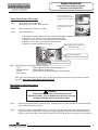
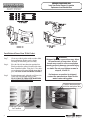
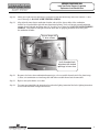
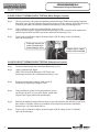
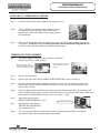
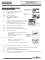
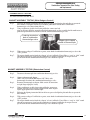
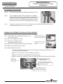
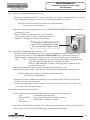
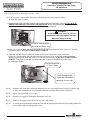
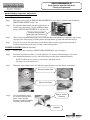
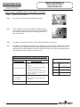
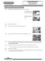
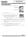
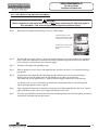
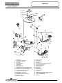
http://waterheatertimer.org/How-to-install-gas-water-heater.html#troubleshoot
The Bradford White
Flammable Vapor Ignition Resistant Water Heater
SERVICE
MANUAL
Troubleshooting Guide
and Instruction for Service
(To be performed ONLY by qualified service providers)
For the Bradford White
Defender Safety System® Models:
MI30T*F(BN,CX)
MI30S*F(BN, CX)
MI303T*F(BN,CX)
MI40T*F(BN,CX)
MI403S*F(BN,CX)
MI404T*F(BN,CX)
MI503*F(BN,CX)
MI50L*F(BN,CX)
MI504S*F(BN,CX)
MI60T*F(BN,CX)
M430T*F(BN,CX)
M440T*F(BN, CX)
M4403S*F(BN,CX)
M4403T*F(BN,CX)
M450S*F(BN,CX)
M4503*F(BN,CX)
M460T*F(BN,CX)
M1XR403S*F(BN,CX)
M1XR504T*F(BN,CX)
M2XR504T*F(BN,CX)
M2C504T*F(BN,CX)
50T65F(BN,CX)
(*) Denotes Warranty Years.
Save this manual for future reference
Manual 44943C
FLAMMABLE VAPOR
IGNITION RESISTANT WATER HEATERS
Table of Contents
3
Page
Service Procedure
Introduction
3
---
Trouble shooting Chart
4
---
Inner Door Gasket Removal, Inspection, Replacement and Installation
5
RG-I
Thermocouple Testing and Replacement
8
RG-II
Pilot Assembly Inspection Cleaning and Replacement
10
RG-III
Piezo Igniter and Electrode Testing
11
RG-IV
Combination Thermostat/Gas Valve Testing and Replacement
12
RG-V
Burner Operation Inspection, Adjustment, Cleaning and Replacement
17
RG-VI
Resettable Thermal Switch Testing and Replacement
20
RG-VII
ScreenLok® Flame Arrestor Cleaning
22
RG-VIII
Dip Tube and Anode Inspection and Replacement
23
RG-IX
Generic Parts List
25
---
INTRODUCTION
The Bradford White DEFENDER Safety System®
The Bradford White DEFENDER Safety System® was designed to resist the ignition of flammable
vapors that can occur outside of the water heater. Use and installation are nearly identical to
previous versions of atmospherically fired and vented water heaters. A number of exclusive design
features are incorporated in the system that will require additional knowledge on the part of the
qualified service provider. The following information will instruct service professionals on the
function, proper diagnosis and repair of water heaters employing the Bradford White DEFENDER
Safety System®.
How the Safety System Works
During normal operation, air for combustion is drawn into the water heater through the opening in
the jacket. This air travels down and around the combustion chamber and enters through holes in
the very bottom of the corrosion-resistant combustion chamber. The air then travels up through the
oriented flame arrestor plate louvers, where the velocity of the air is increased and its direction
altered. The air then mixes in a normal manner with the supplied gas and is efficiently combusted,
producing very low NOx emissions.
In the case where trace amounts of flammable vapors are present in the air flowing into the
combustion chamber, the vapors are harmlessly ignited by the burner / pilot flame. If flammable
vapors are in sufficient quantity to prevent normal combustion, the burner/pilot flame is shut down.
Should the flammable vapors continue to the burner, the flame arrestor plate prevents the flames
from traveling backwards and igniting vapors outside of the combustion chamber. The calibrated,
multipurpose thermal switch recognizes this and shuts down the pilot and main burner. This switch
also deactivates the burner and pilot in the unlikely event of restricted airflow caused by severe lint,
dust or oil accumulation on the arrestor plate.
4
TROUBLESHOOTING CHART
Flammable Vapor Ignition Resistant Water Heaters
SYMPTOM
Pilot Will Not Light
Pilot Will Not
stay lit
when button is
released
Pilot will light but
the main burner
will not come on
Pilot goes out
periodically (after
heating cycles,
once a day, once
a week etc.)
Not enough hot
water
5
PROBABLE CAUSE
CORRECTIVE ACTION
1. No incoming gas or too low gas
pressure.
2. Gas control knob set to wrong position.
3. Pilot light button not being fully
depressed when attempting to light pilot.
4. Pilot orifice or pilot tube is obstructed or
kinked.
5. Pilot electrode not sparking to pilot.
6. Piezo igniter not functioning.
1. Turn on gas supply and/or check line
pressure.
2. Review lighting instruction. Set
combination/thermostat
gas valve to correct position.
3. Review lighting instruction. Fully depress
pilot lighting button.
4. Clean, repair or replace.
5. Verify correct electrode position. Replace
pilot assembly.
6. Replace Piezo igniter.
1. Poor thermocouple connection at
combination thermostat/gas valve.
2. Thermocouple not fully engaged in pilot
assembly bracket.
3. Pilot flame is not fully enveloping the
thermocouple “hot” junction.
4. Weak or defective thermocouple.
5. Open ECO on combination thermostat/
gas valve.
6. Defective magnet in combination
thermostat/gas valve.
7 Resettable thermal switch has opened.
1. Check connection at combination
thermostat/gas valve. Proper tightness
should be finger tight plus ¼ turn.
2. Inspect thermocouple to ensure that it is
fully engaged into pilot bracket.
3. Adjust tip of thermocouple to be fully
engulfed by pilot flame.
4. Check thermocouple and replace if
necessary.
5. Check ECO continuity and replace
combination thermostat/gas valve if
necessary.
6. Check magnet operation and replace
combination thermostat/gas valve if
necessary.
7. Determine cause of switch activation. To
reset, depress button on resettable thermal
switch located on inner door.
1. Combination thermostat/gas valve set too
low for desired water temperature.
2. Combination thermostat/gas valve
temperature is satisfied.
3. Insufficient gas supply or low gas
pressure.
4. Combination thermostat/gas valve has
wide differential or is out of calibration.
1. Adjust temperature dial on combination
thermostat/gas valve.
2. Check temperature dial setting on
combination thermostat/gas valve.
3. Check gas supply and line pressure.
4. Check combination thermostat/gas valve
for proper operation, replace if
necessary.
1. Insufficient combustion air supply.
2. Incorrect, clogged vent system/ vent
terminal or location.
3. Inconsistent gas supply or gas pressure.
1. Combination thermostat/gas valve set too
low for desired water temperature.
2. Cold inlet water temperature is very cold.
3. High demand periods.
4. Incorrectly sized water heater for
application.
5. Combination thermostat/gas valve is out
of calibration/not functioning.
6. Out of spec dip tube is diluting hot water
with cold water.
1. Verify adequate combustion air is available
to the unit. Check and clear Jacket slot
openings of any dirt, dust, restrictions or
other obstructions. Inspect flame arrestor
plate and clean with stiff bristled brush
and/or vacuum to remove any debris
accumulation.
2. Check venting for proper sizing and proper
operation
3. Check gas supply and line pressure.
1. Check dial on combination thermostat/gas
valve.
2.Extremely cold water going into the heater
will decrease the amount of hot water
produced. It may be necessary to temper
incoming water supply.
3. Adjust high demand usage.
4. Contact Plumbing professional.
5. Check combination thermostat/gas valve
for proper operation, replace if
necessary.
6. Inspect dip tube and replace if necessary.
SERVICE
PROCEDURE
1. See Service Procedure
RG-V, Page 12.
4. See Service Procedure
RG-III, Page 10.
5. See Service Procedure
RG-III, Page 10.
6. See Service Procedure
RG-IV, Page 11.
4. See Service Procedure
RG-II, Page 8
5. See Service Procedure
RG-V, Page 14
6. See Service Procedure
RG-V, Page 13
2. See Installation &
operation manual.
3. See Service Procedure
RG-V, Page 12
4. See Service Procedure
RG-V, Page 12
1. See Service Procedure
RG-VIII, Page 22
3. See Service Procedure
RG-V, Page 12
5. See Service Procedure
RG-V, Page 12
6. See Service Procedure
RG-IX, Page 23
SERVICE PROCEDURE RG-I
Inner Door/Gasket Removal, Inspection
Replacement and Reinstallation
Inner Door Removal Procedure
Step 1.
Rotate knob of the combination
thermostat/gas valve to the “OFF” position.
Step 2.
Remove outer jacket burner access door
Step 3.
Inner Door Removal.
For White Rodgers Control,
depress knob slightly and rotate
clockwise to the “OFF” position.
For Robertshaw Control, rotate
knob clockwise to the “OFF”
position.
a) Disconnect resettable thermal switch wire leads (leading from combination thermostat/gas valve).
b) Remove (2) 1/4" hex drive screws from right side inner door.
c) Remove (2) 1/4" drive screws from flange section of inner door.
d) Remove (2) 1/4" drive screws from left side inner door.
e) Remove inner door and inspect per step 4.
Resettable Thermal Switch
Wire Connection
¼" Hex Drive Screws
Right and Left Side Inner Door.
¼" Hex Drive Screws at
Flange Area of Inner Door
Step 4. Fully inspect inner door gaskets for the following:
>Tears
>Other imperfections that will inhibit proper seal
>Missing Material
>Gasket adhesion to inner door
>Cracks
>Material left on combustion chamber (around opening)
>Dirt or debris
If the gasket is not effected by any of the above, gasket replacement is not required. If replacement is required,
proceed to Inner Door Gasket Replacement Procedure.
Inner Door Gasket Replacement
Procedure.
WARNING
If the information in these instructions is not
followed exactly, a fire or explosion may result causing
property damage, personal injury or death.
Step 5.
After inspection of inner door as noted in step 4, completely remove gasket and adhesive residue from right
and left side inner doors as needed.
Step 6.
Use RTV sealant (recommended bead size 1/8") to secure the inner door gasket to the inner door sections
(right & left). Refer to illustration on next page for proper application. Note the overlap configuration in the
flange area of the inner door. Set the flange section first, this will help to achieve the proper over lap position.
6
SERVICE PROCEDURE RG-I
Inner Door/Gasket Removal, Inspection
Replacement and Reinstallation
Installation of Inner Door With Gasket.
Step 7.
Clean any residual gasket residue or other debris
from combustion chamber surface before
installing the inner door/gasket assembly.
Step 8.
Place the left side inner door into position first.
Firmly position the radiused channel of the inner
door around the feedline. Using the 1/4” hex drive
screws from step 3d, secure left side inner door in
place. DO NOT OVER TIGHTEN SCREWS.
Step 9
Position thermocouple, pilot tube and Piezo wire
against left side inner door flange gasket.
DO NOT ROUTE THROUGH RADIUSED
CHANNEL WITH FEEDLINE.
WARNING
Stripped fastener connections may allow
for seal breach of inner door. A seal
breach may result in a fire or explosion
causing property damage, personal injury
or death. Do not over tighten screws in
steps 8, 10 and 11.
If a fastener connection is stripped,
contact the manufacturer listed on the
water heater rating plate.
Position thermocouple,
pilot tube and piezo wire.
Radiused Channel
for Feedline
7
SERVICE PROCEDURE RG-I
Inner Door/Gasket Removal, Inspection
Replacement and Reinstallation
Step 10.
Firmly place right side inner door flange against the left side inner door flange and secure with two ¼” drive
screws from step 3c. DO NOT OVER TIGHTEN SCREWS.
Step 11.
Align right side inner door to combustion chamber and verify the fastener holes of the combustion
chamber are aligned with the right side inner door slotted opening. Verify seal integrity around combustion
opening. Secure right side inner door using 1/4” hex drive screws from step 3b. DO NOT OVER TIGHTEN
SCREWS. Verify both left and right sides of the inner door are properly positioned and sealed against
the combustion chamber.
Secure flange with
¼" drive screws.
Verify threaded hole
alignment with slotted
openings in inner door.
Step 12.
Reconnect lead wires from combination thermostat/gas valve to resettable thermal switch (See photo in step
3). Note, wire terminations are interchangeable with either resettable thermal switch connections.
Step 13.
Replace outer jacket burner access door.
Step 14.
To resume operation follow the instructions located on the lighting instruction label or the lighting instructions
located in the installation and operation manual.
8
SERVICE PROCEDURE RG-II
Thermocouple Testing and Replacement
CLOSED CIRCUIT THERMOCOUPLE TESTING (White Rodgers Control)
Step 1.
Closed circuit testing is the preferred method for testing thermocouple. Following the lighting instruction
label on the heater, proceed to light the pilot and allow to operate for three minuets. If the pilot will not stay
lit, hold the pilot button (located on the combination thermostat/gas valve) down during this test
Step 2.
Using a multimeter capable of measuring millivolts, connect one lead
using an alligator clip to the copper sheath of the thermocouple, use the second lead of the multi meter to
probe the top terminal located at the back of the combination thermostat/gas valve.
Step 3.
If meter reads 10 millivolts or higher, the thermocouple is OK. If reading is below 10 millivolts,
replace the thermocouple.
Probe top terminal on
back of combination
thermostat/gas valve
Alligator clip to copper
sheath of thermocouple
CLOSED CIRCUIT THERMOCOUPLE TESTING (Robertshaw Control)
9
Step 1.
Disconnect thermocouple from combination thermostat/gas valve.
Step 2.
Connect a thermocouple adaptor
(BWC P/N 239-44642-00, Robertshaw P/N 75036) at the
thermocouple location in the combination thermostat/gas valve.
Step 3.
Reconnect thermocouple to adaptor. Make certain all
connections are tight (finger tight plus ¼ turn)
Step 4
Using a multimeter capable of measuring millivolts, connect
one alligator clip to the set screw of the adaptor, and the other
alligator clip to copper portion of the thermocouple.
Step 5.
Following the lighting instruction label on the heater, proceed to light the pilot and allow to operate for
three minuets. If the pilot will not stay lit, hold the red reset button (located on the combination
thermostat/gas valve) down during this test
Step 6.
If meter reads 13 millivolts or higher, the thermocouple is OK. If reading is below 13 millivolts
replace the thermocouple.
SERVICE PROCEDURE RG-II
Thermocouple Testing and Replacement
OPEN CIRCUIT THERMOCOUPLE TESTING
Step 1.
Disconnect thermocouple from combination thermostat/gas valve.
Step 2.
Using a multimeter capable of measuring millivolts, connect
one alligator clip to the end ball or contact portion of the
thermocouple, and the other alligator clip to copper portion of
the thermocouple.
Step 3.
Following the lighting instruction label on the heater, proceed to light the pilot and allow to operate for
three minutes. It will be necessary to hold the pilot button down continuously throughout this test.
A reading of 20 to 30 millivolts indicates good thermocouple output.
THERMOCOUPLE REPLACEMENT
Step 1.
Turn off gas supply to water heater. Rotate knob of combination
thermostat/gas valve to “OFF” position.
For White Rodgers Control,
depress knob slightly and rotate
clockwise to the “OFF” position.
For Robertshaw Control, rotate
knob clockwise to the “OFF”
position.
Step 2.
Remove outer jacket door.
Step 3.
Remove right side of inner door per SERVICE PROCEDURE RG-I, steps 3a through 3c.
Step 4
Disconnect thermocouple from combination thermostat/gas valve (3/8" wrench). Locate other end of
thermocouple inside of combustion chamber and remove from pilot bracket. Pull firmly pulling away
from the pilot assembly.
Step 5.
Install new thermocouple into pilot bracket making certain the thermocouple is fully engaged into the pilot
bracket. Position thermocouple against left side inner door flange at its original position. Connect other end of
thermocouple to combination thermostat/gas valve (finger tight + ¼ turn).
Step 6.
Inspect inner door gasket per
SERVICE PROCEDURE RG-I, Step 4.
Thermocouple position
Step 7.
Install right side inner door per
SERVICE PROCEDURE RG-I,
Step 10 through Step 13
Step 8.
To resume operation follow the instructions located on the lighting instruction label or the lighting
instructions located in the installation and operation manual.
10
SERVICE PROCEDURE RG-III
Pilot Assembly Inspection, Cleaning and Replacement
PILOT/ELECTRODE ASSEMBLY INSPECTION,
CLEANING AND REPLACEMENT
For White Rodgers Control,
depress knob slightly and rotate
clockwise to the “OFF” position.
Step 1.
Turn off gas supply to water heater. Rotate knob
of combination thermostat/gas valve
to “OFF” position.
For Robertshaw Control, rotate
knob clockwise to the “OFF”
position.
Step 2.
Remove outer jacket door.
Step 3.
Remove right side of inner door per
SERVICE PROCEDURE RG-I, steps
3a through 3c.
Step 4
Disconnect thermocouple (3/8" wrench), pilot tube (7/16" wrench),
and feedline (¾" wench) from combination thermostat/gas valve.
NOTE: Feedline nut for natural gas control
uses right hand threads, LP control uses left hand thread.
Feedline
Nut
Step 5
Disconnect piezo ignition wire from piezo igniter.
Step 6.
Remove burner assembly from combustion chamber.
Step 7.
Remove pilot/electrode assembly from feedline (¼" drive tool)
Step 8.
Inspect pilot for the following:
a) Primary air openings for blockage. Must be free from any
debris (dirt, lint, etc).
b) Kinks or cracks in the pilot tube. If found,
the pilot must be replaced.
Step 9.
Primary Air
Opening
Inspect pilot orifice:
a) Remove ½" nut from bottom of pilot assembly.
b) Remove pilot tube and pilot orifice.
c) inspect pilot orifice for blockage, must be cleaned or replaced.
Pilot Orifice
11
Step 10.
Install pilot/electrode assembly to feedline, secure with screw from step 7.
Step 11.
Re-Install burner assembly into combustion chamber, connect feedline, pilot tube and thermocouple
to combination thermostat/gas valve.
Step 12.
Install inner door per SERVICE PROCEDURE RG-I, step 4 through 13.
Step 13.
To resume operation follow the instructions located on the lighting instruction label or the lighting instructions
located in the installation and operation manual.
SERVICE PROCEDURE RG-IV
Piezo Igniter, Electrode Testing and Replacement
PIEZO IGNITER, ELECTRODE TESTING AND REPLACEMENT
With the pilot not in operation (no pilot flame) you can check the Piezo and electrode circuit by viewing pilot
thru the sight glass located on the inner door and observing the spark action.
Step 1.
Remove outer jacket door.
Step 2.
Repeatedly depress the Piezo igniter while viewing the pilot thru the sight glass. If a spark is
present, the circuit is OK. If there is no spark, proceed to step 3.
Repeatedly
Depress Piezo
Igniter
View spark
Action through
Sight glass
Step 3
Remove orange wire from Piezo igniter and install a jumper wire in its place. Hold the other end of
the jumper by the wire insulation or using an insulated tool, next to an unpainted surface such as
the feedline or gas valve and depress the Piezo igniter. If there is a spark, the igniter is OK, the pilot
is not functioning and must be replaced, see SERVICE PROCEDURE RG-III for pilot
replacement. If no spark is present the igniter is not functioning and must be replaced.
Step 4
With orange wire disconnected from piezo igniter. Using a common screw driver, place blade of
screw driver under piezo bracket and gently pry bracket from front of combination thermostat/
gas valve and unhook bracket from rear of combination thermostat/gas valve.
Common Screw
Driver
12
SERVICE PROCEDURE RG-V
Combination Thermostat/Gas Valve Testing
and Replacement
Combination Thermostat/Gas Valve Testing and Replacement
The combination thermostat/gas valve is a non repairable device. If trouble shooting has determined a problem with the
combination thermostat/gas valve, it must be replaced.
If the burner and/or pilot do not function, service checks for gas pressure, thermocouple output, magnet assembly and
ECO are to be performed. If these check OK, the combination thermostat/gas valve may be faulty.
LINE PRESSURE
The combination thermostat/gas valve is designed for a maximum line pressure of 14.0" w.c. and a minimum line
pressure of 1.0"w.c. over the water heater rated manifold pressure. Line pressure must be checked with burner on and
burner off to assure proper readings.
MANIFOLD PRESSURE TESTING (this procedure assumes a maximum line pressure of 14.0" w.c.)
Step 1.
Set combination thermostat/gas valve to “OFF” position.
13
Step 2.
Remove pressure tap plug (3/16" Allen wrench) and install
pressure tap (7/16 wrench)
Step 3.
Connect manometer to pressure tap.
Step 4
Follow lighting instructions and proceed to light
main burner and observe manometer reading.
Step 5
Proper operating range for natural gas is 4.0 ±0.3" W.C.
Proper operating range for L.P. gas is 10.0 ±0.5" W.C.
Step 6
If pressure is OK, set combination thermostat/gas valve to “OFF”
remove manometer and pressure tap and replace pressure tap plug. Check for gas leaks before placing water
heater back in operation. If pressure is out of the specification noted in step 5, proceed to step 7 or 8 for proper
service procedure.
Step 7
For White Rodgers control, the manifold pressure is not adjustable. If manifold pressure is outside the range
in step 5, the control must be replaced.
Step 8
For Robertshaw control, the manifold pressure is adjustable, proceed to step 9 for adjustment procedure
Step 9
While burner is in operation, remove regulator access cap to expose the regulator adjusting screw. With small
screw driver, rotate adjusting screw clockwise to increase pressure and counter clockwise to decrease pressure.
Step 10
Replace regulator access cap, set combination thermostat/gas valve to “OFF”. Remove manometer and
pressure tap and replace pressure tap plug. Check for gas leaks before placing water heater back in operation.
Pressure Tap
Shown Installed
SERVICE PROCEDURE RG-V
Combination Thermostat/Gas Valve Testing
and Replacement
THERMOCOUPLE TESTING
See SERVICE PROCEDURE RG-II
MAGNET ASSEMBLY TESTING (White Rodgers Control)
Step 1.
Following the lighting instruction label on the heater, proceed to light the pilot and allow to operate for
three minuets. If the pilot will not stay lit, hold the pilot button (located on the combination
thermostat/gas valve) down during this test
Step 2.
Using a multimeter capable of measuring millivolts, connect one lead
using an alligator clip to the copper sheath of the thermocouple, use the second lead of the multi meter to
probe the top terminal located at the back of the combination thermostat/gas valve.
Probe top terminal on
back of combination
thermostat/gas valve
Alligator clip to copper
sheath of thermocouple
Step 6.
With a meter reading of 13 millivolts or greater, rotate knob of combination thermostat/gas valve to the
“OFF” position.
Step 7.
The magnet should remain closed for a drop of at least 6 millivolts. You will here a “snap” or “click” sound
when the magnet opens, if you hear this sound prior to a drop of 6 millivolts, the magnet is out of
specification and the combination thermostat/gas valve should be replaced.
MAGNET ASSEMBLY TESTING (Robertshaw Control)
Step 1.
Disconnect thermocouple from combination thermostat/gas valve.
Step 2.
Connect a thermocouple adaptor
(BWC P/N 239-44642-00, Robertshaw P/N 75036) at the
thermocouple location in the combination thermostat/gas valve.
Step 3.
Reconnect thermocouple to adaptor. Make certain all connections
are tight (finger tight plus ¼ turn).
Step 4
Using a multimeter capable of measuring millivolts, connect one
alligator clip to the set screw of the adaptor and the other alligator
clip to copper portion of the thermocouple.
Step 5.
Following the lighting instruction label on the heater, proceed to light the pilot and allow to operate for
three minuets.
Step 6.
With a meter reading of 13 millivolts or greater, rotate knob of combination thermostat/gas valve to the
“OFF” position.
Step 7.
The magnet should remain closed for a drop of at least 6 millivolts. You will here a “snap” or “click” sound
when the magnet opens, if you hear this sound prior to a drop of 6 millivolts, the magnet is out of
specification and the combination thermostat/gas valve should be replaced.
14
SERVICE PROCEDURE RG-V
Combination Thermostat/Gas Valve Testing
and Replacement
ECO (Energy Cut Off) TESTING
Step 1.
Disconnect thermocouple from combination thermostat/gas valve.
Step 2.
Using a multimeter capable of measuring Ohms (or continuity),
attach one lead (alligator clip) to the pilot tube. Insert the other lead
(probe) fully into the magnet opening, Be sure the probe makes
contact only at the top center of the magnet opening. Do not allow
the probe to make contact with the threaded sides of the opening.
Step 3.
If continuity is indicated, the ECO is OK. If continuity is not indicated, the ECO has opened and the
combination thermostat/gas valve must be replaced.
COMBINATION THERMOSTAT/GAS VALVE REPLACEMENT
Step 1. Rotate knob of the combination thermostat/gas valve
to the “OFF” position.
For White Rodgers Control,
depress knob slightly and rotate
clockwise to the “OFF” position.
Step 2. Turn off gas supply to water heater.
Step 3. Disconnect gas supply line from
combination thermostat/gas valve.
Step 4. Turn off water supply and drain water heater completely.
For Robertshaw Control, rotate
knob clockwise to the “OFF”
position.
Step 5. Remove outer jacket burner access door.
Step 6. Right side inner door removal.
a) Disconnect resettable thermal switch wire leads (leading from combination thermostat/gas valve)
and remove wire tie from feedline.
b) Remove (2) 1/4" hex drive screws from right side inner door.
c) Remove (2) 1/4" drive screws from flange section of inner door.
d) Remove right side inner door and set aside. Be careful not to damage gasket material on inner door.
Remove
Wire Tie
Resettable Thermal Switch
Wire Connection
¼" Hex Drive Screws shown on
Right Side Inner Door.
¼" Hex Drive Screws at
Flange section of Inner Door
15
SERVICE PROCEDURE RG-V
Combination Thermostat/Gas Valve Testing
and Replacement
Step 7. Removal of combination thermostat/gas valve.
a) Disconnect main burner feedline (¾” wrench), pilot tube (7/16" wrench) and thermocouple (3/8" wrench)
from combination thermostat/gas valve & remove burner from combustion chamber.
NOTE: Feed line nut for natural gas control uses right hand threads,
LP control uses left hand thread.
b) Remove piezo bracket with piezo igniter (refer to SERVICE PROCEDURE RG-IV) from Combination
Thermostat/Gas Valve.
c) Remove Combination Thermostat/Gas Valve from heater,
Wrench Boss
rotating counter clockwise using a control body wrench or a
length of ½" NPT pipe threaded into inlet of control.
To remove or install control, insert
only ½" NPT threaded pipe into inlet
and use to loosen or tighten control.
Step 8. Installation of Combination Thermostat/Gas Valve.
a) Install new combination thermostat/gas Valve using a control body wrench or a length of ½" NPT
pipe threaded into inlet of control. DO NOT OVER TIGHTEN. Use caution not to damage cast
aluminum body of combination thermostat/gas valve. Be certain not to damage the bundled wire
leads.
Note: Combination thermostat/gas Valve must be installed in proper upright position to
assure the feedline will align properly at the inner door flange.
DO NOT OVER TIGHTEN. If control is turned past proper alignment, do not
reverse direction to align.
b) Reattach Piezo bracket with Piezo igniter to combination thermostat/gas valve.
c) Reattach main burner feedline, pilot tube and thermocouple to combination thermostat/gas valve.
NOTE: Feedline nut for natural gas control uses right hand threads,
LP control uses left hand thread.
d) Gather wire leads of combination thermostat/gas valve and Piezo igniter and secure along side of
feedline using new wire tie provided.
e) Connect gas supply piping to inlet of control. Use back up wrench on wrench boss of control, never
use back up wrench on body of control.
Step 9. Reinstallation of inner door assembly.
a) Prior to reinstallation of inner door, fully inspect inner door gasket for the following:
> Tears
> Gasket Adhesion to inner door
> Missing Material > Other imperfections that will inhibit proper seal
> Cracks
> Material left on combustion chamber
> Dirt or debris
If the gasket is not effected by any of the above, gasket replacement will not be required. If replacement is
required, replace using new gasket kit following the instructions provided with kit.
16
SERVICE PROCEDURE RG-V
Combination Thermostat/Gas Valve Testing
and Replacement
Step 9. Reinstallation of inner door assembly. (cont.)
b) Clean any gasket residue or other debris from combustion chamber surface before installing
the inner door/gasket assembly.
c) Position thermocouple, pilot tube and Piezo wire against left side inner door flange gasket. DO NOT ROUTE
THROUGH RADIUSED CHANNEL WITH FEEDLINE. Be sure that thermocouple and pilot tube are not
in position to interfere with outer jacket burner access door when reinstalled.
WARNING
A seal breach may result in a fire or
explosion causing property damage,
personal injury or death.
Position thermocouple,
pilot tube and Piezo wire.
d) Firmly place right side inner door flange against the left side inner door flange and secure with two ¼” hex drive
screws from step 6c. DO NOT OVER TIGHTEN SCREWS.
e) Align right side inner door to combustion chamber and verify the fastener holes of the combustion
chamber are aligned with the right side inner door slotted openings. Verify seal integrity around combustion
opening. Secure right side inner door using 1/4” hex drive screws from step 6b. DO NOT OVER TIGHTEN
SCREWS. Verify both left and right sides of the inner door are properly positioned and sealed against
the combustion chamber.
Secure flange with
¼" drive screws.
Verify threaded hole
alignment with slotted
openings in inner door.
17
Step 10.
Reconnect wire leads from combination thermostat/gas valve to resettable thermal switch (See photo in step
6). Note: wire terminations are interchangeable with either resettable thermal switch connection.
Step 11.
Replace outer jacket burner access door.
Step 12.
Reconnect gas supply to Combination Thermostat/Gas Valve.
Step 13.
Resume water supply to water heater. Be sure tank is full of water.
Step 14.
To resume operation follow the instructions located on the lighting instruction label or the lighting instructions
located in the installation and operation manual.
SERVICE PROCEDURE RG-VI
Burner Operation Inspection, Adjustment
Cleaning and Replacement
MAIN BURNER: Inspection, Adjustment,
Cleaning and Replacement
At periodic intervals (not more then 6 months) a visual inspection should be made of the main burner for proper operation
and to insure no debris accumulating.
Main burner should light smoothly from pilot and burn with a blue flame with a minimum of yellow tips.
Steel burner models have a self adjusting air mixture and do not have an adjustable air shutter. Cast iron burner can have
the gas and air mixture properly proportioned by adjusting the air shutter on the mixer face of the main burner (see step 2
below).
Main burner must be free from any debris accumulation that may effect burner operation (see burner cleaning procedure
on page 17).
CAST IRON BURNER ADJUSTMENT
DANGER
Under no circumstances shall flammable materials be used or stored in the vicinity of the water heater. With
the inner door removed the Bradford White Defender Safety System will be inactivated. If flammable vapors
are present, a fire or explosion may result causing property damage, personal injury or death.
Upon completion of the cast iron burner adjustment procedure, the inner door must be replaced per
SERVICE PROCEDURE RG-1, steps 4 through 14 to reactivate Bradford White Defender Safety System.
WARNING
Inner door and burner components may be HOT when performing this operation. Take
necessary precaution to prevent personal injury.
Step 1.
With main burner in operation, remove right side inner door per service procedure I, steps 3b & 3c. Be sure to
maintain wire connection to resettable thermal switch for this adjustment procedure.
Step 2.
To adjust for proper burning, loosen the air shutter nut, rotate the shutter to close the opening in the burner,
then slowly rotate the shutter until the yellow tips disappear and the flame becomes blue. Tighten the air
shutter nut. Too much air will cause the flame to lift off the burner ports and create noisy burner operation.
Too little air (yellow tips) will result in soot formation.
Place right side inner door into proper position to confirm proper burner flame pattern and correct air shutter
adjustment. It may be necessary to allow the burner to operate for several minutes for burner flame to stabilize.
Air Shutter Nut
18
SERVICE PROCEDURE RG-VI
Burner Operation Inspection, Adjustment
Cleaning and Replacement
MAIN BURNER: Inspection, Adjustment,
Cleaning and Replacement (cont.)
Step 3.
Fully inspect inner gasket per SERVICE PROCEDURE RG-I, step 4. Replace gasket if required following
SERVICE PROCEDURE I, steps 5 & 6.
Step 4.
Be certain that thermocouple, pilot tube and piezo wire are
routed by inner door flange as shown and Reinstall inner
door per SERVICE PROCEDURE RG-I, step 10 and 11.
Position thermocouple,
pilot tube and Piezo wire.
Step 5.
Observe burner operation through sight glass of inner door. Burner should operate as adjusted in step 2, if not,
repeat procedure compensating air shutter position for proper burner operation with inner door in place.
Step 6.
It may be necessary to clean main burner or main burner orifice to achieve proper burner operation. If
cleaning is required proceed to burner cleaning section in this procedure.
BURNER CLEANING (Steel & Cast Iron)
Step 1.
Remove inner door assembly per SERVICE PROCEDURE RG-I, steps 1 through 3c.
Step 2.
Disconnect main burner feed line (¾ wrench), pilot tube (7/16 wrench) and thermocouple (3/8) wrench
from combination thermostat gas valve and remove burner assembly from combustion chamber.
NOTE: Feedline nut for natural gas control uses right hand threads,
LP control uses left hand thread.
Step 3.
Thoroughly inspect burner surface area and burner ports and remove any loose debris accumulation.
Burner Surface Area
Burner Port Area
Step 4.
On cast iron burners, inspect
for any debris build up inside
burner venturi. If found,
disconnect feedline from burner
and remove debris build up.
Burner Venturi
Opening
Feedline
19
SERVICE PROCEDURE RG-VI
Burner Operation Inspection, Adjustment
Cleaning and Replacement
BURNER CLEANING (Cont.)
Step 5.
Disconnect (unscrew) Main burner (stamped steel “B” burner) from main
burner orifice or on cast iron burners (“C” burner), loosen air shutter &
disconnect (unscrew) feedline from burner.
Step 6.
Remove main burner orifice from feed line (½” wrench on steel
burner, 3/8" wrench on cast iron). Inspect and clean if necessary.
Step 7.
Remove pilot assembly, refer to SERVICE PROCEDURE RG-III for cleaning and inspection.
Step 8.
Reassemble burner.
Step 9.
Inspect combustion chamber area of heater prior to reinstallation of burner assembly. If cleaning is required,
refer to SERVICE PROCEDURE RG-VIII.
Step 10.
Reinstall burner assembly into combustion chamber, reconnect feedline, thermocouple and pilot tube to
the combination thermostat/gas valve.
Step 11.
Reinstall inner door per SERVICE PROCEDURE RG-I, steps 4 through 13.
Step 12.
To resume operation, follow the instructions located on the lighting instruction label or the lighting
instructions located in the installation and operation manual.
20
SERVICE PROCEDURE RG-VII
Resetting Thermal Switch
Testing and Replacement
RESETTABLE THERMAL SWITCH CONTINUITY TESTING
Step 1.
Remove outer jacket door.
Step 2.
Disconnect wire leads from resettable thermal switch.
Step 3.
Using a multimeter capable of measuring continuity (Ohms),
place one probe of meter on one of the brass connection tabs of
the resettable thermal switch, and the remaining probe on the
other connection tab.
Step 4.
If continuity is indicated, the switch is closed, allowing millivolt current to pass.
Step 5.
If continuity is not indicated, the switch is open, possibly due to an over heating condition. The switch is
designed to open at predetermined temperatures depending on model. An open switch can be reset by
depressing the red colored button located at the center of the switch. The overheating condition must be
determined prior to putting the heater back in service.
PROBABLE CAUSE FOR RESETTABLE THERMAL SWITCH ACTIVATION
PROBABLE CAUSE
CORRECTIVE ACTION
1. Verify adequate combustion air supply is
available.
Insufficient combustion Air
2. Clear jacket slot openings of any dirt, dust,
restrictions or other obstructions.
3. inspect flame arrestor plate and clean with
stiff brush and/or vacuum to remove scale
deposits and debris.
1. Weak switch or switch
out of calibration.
2. Incorrect switch.
Flammable vapor incident
21
1. Replace resettable thermal switch
2. Verify switch color code and approximate
temperature.
1. Replace water heater.
Resettable thermal switch
color code reference.
Color Code
Approximate switch
activation temperature
(open)
Blue
240°
Yellow
270°
Red
290°
SERVICE PROCEDURE RG-VII
Resetting Thermal Switch
Testing and Replacement
RESETTABLE THERMAL SWITCH REPLACEMENT
Step 1.
Rotate knob of combination thermostat gas valve to the off position.
For White Rodgers Control,
depress knob slightly and rotate
clockwise to the “OFF” position.
For Robertshaw Control, rotate
knob clockwise to the “OFF”
position.
Step 2.
Remove outer jacket door.
Step 3.
Disconnect wire leads from resettable thermal switch.
Step 4.
Remove resettable thermal switch from inner door (Phillips screw driver)
Step 5.
Place new resettable thermal switch in place. Be sure contact surface of resettable thermal switch and inner
door are free of any debris. Secure resettable thermal switch into place using screws from step 4. DO NOT
OVER TIGHTEN SCREWS.
Step 6.
Reconnect wire leads from combination thermostat/gas valve to resettable thermal switch.
Note: Wire termination are interchangeable with either resettable thermal switch connection.
Step 7.
Replace outer jacket door
Step 8.
To resume operation follow the instructions located on the lighting instruction label or the lighting instruction
located in the installation and operation manual.
22
SERVICE PROCEDURE RG-VIII
ScreenLok® Flame Arrestor Cleaning
ScreenLok® Flame Arrestor Cleaning
Step 1.
Rotate knob of combination thermostat gas valve to the off position.
For White Rodgers Control,
depress knob slightly and rotate
clockwise to the “OFF” position.
For Robertshaw Control, rotate
knob clockwise to the “OFF”
position.
Step 2.
Remove outer jacket door.
Step 3.
Remove inner door per SERVICE PROCEDURE RG-I, step 3a through 3e.
Step 4.
Disconnect main burner feed line (¾ wrench), pilot tube (7/16 wrench)
and thermocouple (3/8) wrench from combination thermostat gas valve
and remove burner assembly from combustion chamber.
NOTE: Feedline nut for natural gas control uses right hand threads,
LP control uses left hand thread.
Feedline
Nut
Step 5.
Clean ScreenLok® Flame Arrestor using stiff brush, compressed air and/or shop vacuum to remove any scale
or other debris accumulation. Using a soft brush, clear jacket openings of any dirt, dust, restrictions or other
obstructions.
Step 6.
Remove any debris from burner assembly per SERVICE PROCEDURE RG-V and reinstall burner assembly
into combustion chamber.
Step 7.
Reconnect feedline, thermocouple and pilot tube to the combination thermostat/gas valve.
Step 8
Reinstall inner door per SERVICE PROCEDURE RG-I, steps 4 through 13.
Step 9.
To resume operation follow the instructions located on the lighting instruction label or the lighting instruction
located in the installation and operation manual.
23
SERVICE PROCEDURE RG-IX
Dip Tube and Anode
Inspection and Replacement
DIP TUBE INSPECTION AND REPLACEMENT
WARNING
Heater components and stored water may be HOT when performing the following steps in
this procedure. Take necessary precaution to prevent personal injury.
Step 1.
Rotate knob of combination thermostat/gas valve to “OFF” position.
For White Rodgers Control,
depress knob slightly and rotate
clockwise to the “OFF” position.
For Robertshaw Control, rotate
knob clockwise to the “OFF”
position.
Step 2.
Turn off cold water supply to heater. Connect hose to drain spigot of water heater and route to an open drain.
Open a nearby hot water faucet to vent heater for draining. Open drain spigot of hot water heater and allow
heater to drain to a point below the inlet connection nipple.
Step 3.
Disconnect inlet nipple from plumbing system.
Step 4
With an appropriate wrench, remove inlet nipple/dip tube from the water heater. Use caution not to damage
pipe threads.
Step 5.
Visually Inspect inlet nipple/dip tube. Inlet nipple/dip tube should be free of cracks and any blockage.
Hydro-jets located near the bottom of the dip tube should be open and free of any blockage.
Anti-siphon hole located approximately 6" from the bottom of nipple, should be free of any blockage.
Any damage such as cracks, restriction due to deformation or unintentional holes are not field repairable
and the inlet nipple/dip tube must be replaced.
Step 6.
Upon completion of inspection or subsequent replacement, reinstall inlet nipple/dip tube into heater. Connect
nipple to plumbing system, resume water supply and refill heater with water.
Step 7.
To resume operation follow the instructions located on the lighting instruction label or the lighting instructions
located in the installation and operation manual.
24
SERVICE PROCEDURE RG-IX
Dip Tube and Anode
Inspection and Replacement
ANODE INSPECTION AND REPLACEMENT
WARNING
Heater components and stored water may be HOT when performing the following steps in
this procedure. Take necessary precaution to prevent personal injury.
Step 1.
Turn off water supply to water heater. Rotate knob of combination thermostat/gas valve to “OFF” position.
For White Rodgers Control,
depress knob slightly and rotate
clockwise to the “OFF” position.
For Robertshaw Control, rotate
knob clockwise to the “OFF”
position.
Step 2.
Turn off cold water supply to heater. Connect hose to drain spigot of water heater and route to an open drain.
Open a nearby hot water faucet to vent heater for draining. Open drain spigot of hot water heater and allow
heater to drain to a point below the outlet connection nipple.
Step 3.
Disconnect outlet nipple from plumbing system.
Step 4
With an appropriate wrench, remove outlet nipple/anode from the water heater. Use caution not to damage
pipe threads.
Step 5.
Visually Inspect outlet nipple/anode. Outlet nipple/anode should show signs of depletion, this is normal.
If depletion is ½ of the original anode diameter (approximately ¾” diameter), replacement is recommended.
If any of the steel core of the anode is exposed, replacement is recommended.
Step 6.
Upon completion of inspection or subsequent replacement, reinstall outlet nipple/anode into heater. Connect
nipple to plumbing system, resume water supply and refill heater with water.
Step 7.
To resume operation, follow the instructions located on the lighting instruction label or the lighting
instructions located in the installation and operation manual.
25
PARTS LIST
1
2
3
4
5
6
7
8
9
10
11
12
14
15
16
17
18
19
Draft Hood
Hot Water Outlet/Anode
Cold Water Inlet Tube
Flue Baffle
T&P Relief Valve
Thermostat
Piezo Igniter
Brass Drain Valve
Screw-#8-18 x 3/4 Hex Washer Head
Screw-#10-12 x 3/4 Hex Washer Head
Left Side Inner Door with Gasket
Complete Right Side Inner Door
Resettable Thermal Switch
Screw #6-20 x 3/8 PHCR
Outer Door
Complete BN Burner Assembly
BN Burner Only
Main Burner Orifice
20
21
22
23
24
25
26
27
28
29
30
31
32
33
34
35
36
Pilot Assembly
Pilot Orifice
Thermocouple
Feed Line
Complete Cast Iron Burner Assembly
Cast Iron Burner Only
Main Burner Orifice
Pilot Assembly
Pilot Orifice
Air Shutter
Air Shutter Nut
Thermocouple
Feed Line
ASSE Approved Mixing Valve (Optional)
¾ NPT Tank Plug (XR models)
Inner Door Gasket Kit
Wire Tie
26
NOTES
NOTES
Application & Sizing/800-523-2931
Fax/215-641-1612
Email
[email protected]
[email protected]
www.bradfordwhite.com
www.bradfordwhitecanada.com