1
~100·~C/R,=an:(t·5.00_~C/R ~~:
Service Manual
L.=r:. t:>)tJPy
.3
•
\
4
I
./
..,16-------- -----.
-- --- -------- __ -- -.-._---._ ..
. __
.0.
Table of Contents
CHAPTER 1 INTRODUCTION
1
We're Here to Help
1
CHAPTER 2 ASSEMBLY
3
Unpack BikeMax
3
Assembling the Upright BikeMax (BMU)
Attach the Display Upright
Attach the Display Console
Attach the Handlebar
4
4
5
5
Assembling the Recumbent BikeMax (BMR)
Attach the Seat Back Assembly
Attach the Display Upright
6
6
6
Attach the Display Console
7
Install the Optional Polar Heart Rate Receiver
Plugging in the BikeMax
8
8
8
Connecting Bikes for Racing
CHAPTER 3 TROUBLESHOOTING
Where to Start
Electrical Cabling
Isolating Mechanical Noise
Mechanical Noise in the Crank Arm Area
Mechanical Noise in the Second Stage Pulley Area
Mechanical Noise in the Alternator Area
CHAPTER 4 USING TEST MODE
BikeMax 3000 Test Mode
Field Indicators
_ Testing Display LEDs
Advanced Diagnostic Information
Odometer
Leaving Test Mode
BikeMax 1000 Test Mode
The Test Mode Dis.play
Heart Monitor Information
Testing Display LEDs
Leaving Test Mode
11
11
12
15
15
15
16·
17
17
17
17
18
19
19
19
19
20
20
20
CHAPTER 5 COMPONENT REPAIR AND REPLACEMENT
Cover Removal
External Power Supply
First Stage Drive
21
22
23
24
Table of Contents
"Page ii
Idler Pulley
Second Stage Drive
Replacing the Secondary Belt
Adjusting the Secondary Belt
Replacing the Second Stage Assembly
Engine Assembly
Removing the Engine Assembly
Installing the New Engine Assembly
Alternator
Removing the Alternator
Installing the New Alternator
RPM Sensor
Alternator Control Board
Battery
CardioTouch Heart Rate Receiver
Recumbent Bike CardioTouch Troubleshooting
Upright Bike CardioTouch Troubleshooting
Polar Heart Rate Receiver
Recumbent Bike Polar Troubleshooting
Upright Bike Polar Troubleshooting
Extrusion Tube Removal and Installation: BikeMax-R Only
.26
27
27
27
28
29-
29
30
32
32
33
35 -
38
39
40 .
41
42
43
43
44
45
APPENDIX A PARTS LIST
47
APPENDIX B ADVANCED ELECTRICAL TROUBLESHOOTING
49
The Power-Up Sequence
Troubleshooting Procedure
.Before You Begin
Troubleshooting Flowchart for Dead Alternator BikeMax
The Troubleshooting Sequence
APPENDIX C ENGINEERING DRAWINGS
49
50
50
52
53
57
CHAPTER 1
INTRODUCTION
Welcome to the BikeMax 100013000 Service Manual. This book can help Tectrix-trained service
personnel diagnose and correct almost any problem with a BikeMax alternator bike. In addition
to this introduction, it covers the following subjects:
Chapter 2
Assembly instructions.
Chapter 3
Basic troubleshooting procedures for electrical and meGhanical problems,
and instructions on where to go next.
Chapter 4
How to use BikeMax's test mode feature.
Chapter 5
A series of short segments on each component of the BikeMax,
describing how to check and, if necessary, replace it.
Appendix A
Parts list
Appendix B
Advanced electrical troubleshooting techniques.
Appendix C
Engineering drawings.
We're Here to Help
If you have any questions about any of the information in this book, or if you're still having
problems with your BikeMax after following all of the appropriate instructions, please contact us
so we can help you get riding again. You can reach our technical support department in any of
three ways:
•
By phone, Monday through Friday: call 800/767-8082 or 508/533-4300, and ask for
Technical Support.
•
Send us a fax at 508/533-5183.
. -::1:
-
-.
: ~ ..::
CHAPTER 2
ASSEMBLY
It's easy to assemble BikeMax-it will probably take about 45 minutes. You need these common
tools:
•
•
•
3/16" Hex (Allen) wrench
#2 Phillips screwdriver
~"box end or open-end wrench (if you have the optional Polar heart rate monitor).
Here's an overview of the steps in the assembly:
1. Unpack BikeMax and make sure you have all the parts.
2. Follow the detailed assembly instructions. There are separate sections on assembling the
recumbent (BikeMax-R) and upright (BikeMax-U) bikes.
3. If you choose to, plug in your BikeMax with the optional external power supply.
4. If you -have more than one BikeMax, connect the communications ports to allow group
raCIng.
Unpack BikeMax
Cut and remove the nylon tie straps holding the chassis feet to the pallet. Remove all the other
parts from the shipping carton.
Chapter 2 - Assembly
Page 4
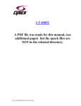
Assembling .the Upright BikeMax (BMU)
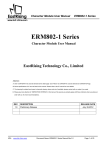
Figure 2-1
Attach the Display Upright
Position the display upright (3) over the chassis and plug the ribbon cable from the upright to the
ribbon cable in the chassis. Tuck the cables inside the neck of the chassis (2) to make sure they
don't get pinched when you attach the display upright. Slide the display upright (3) down over
the neck on the chassis. Using a 3/16" hex wrench, secure them with two 5/16" by 1" button-head
screws (7) and washers (8).
BikeMax 1000 / 3000 Service Manual
•
Page 5
IT your bike has a CardioTouch heart rate monitor:
Remove the upper three round plugs from the display upright. Feed the cable from the
CardioTouch handlebars through the large hole in the display upright until it emerges
through the hole in the display console mounting plate. Attach the handlebars to the
display upright with two 1/2" screws.
~ your
bike has a Polar heart rate receiver:
Remove th~ 3 circular plastic plugs that are installed in a vertical pattern on the display upright
tube; there are 2 small plugs surrounding a larger plug.
The Polar cable-a short cable with a white "polar" label near one end-must be routed
from the largest of these openings up through the upright and attached to the display
console. Feed the unlabeled end into the large round opening and up until it comes out the
top of the upright. Plug the end of the cable with the white label into the connector on the
receiver. Verify that the tab on the connector locks the brown 3-conductor cable connector
into place.
Position the receiver so the locking tab on the connector is on top, nearest to the console. IT there
is an UP ARROW on the receiver, it should be pointing toward the console. Secure the receiver to
the display upright tube with 2 PhilliP.s screws supplied with the kit.
Attach the Display Console
Remove the display console from the configuration kit. Attach the ribbon cable from the display
upright to the back of the display board. The connector is keyed so you cannot insert it
backwards. Attach the green ground cable to the single flat connector next to the ribbon cable
connector. Make sure the cables are frrmly connected before continuing.
•
If you have the CardioTouch or Polar heart rate monitor option, attach the heart rate
monitor cable to the back of the console.
Use the four Phillips head screws from the configuration kit to attach the display console to the
console back-plate. See Figure 2-3.
Attach the water bottle holder to the back plate using three screws. Important: if you choose not
to install the water bottle holder, you must still screw the three screws into th~ open holes in the
back plate to protect the electronics from the environment.
Attach the Handlebar
Use the 3/16" hex wrench to attach the handlebar (4) to the console back-plate with four 5/16"
button-head screws (5) and lock washers (6).
Page 6
Chapter 2 - Assembly ...
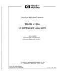
Assembling the Recumbent BikeMax (BMR)
3
7
~1l
Polar cable
(3-wire)
DETAIL A
Location of top
cover screw
Figure 2-2
Attach the Seat Back Assembly
(See Figure 2-2.) Attach the seat back assembly (2) t9 the seat shuttle with four 5/16 x 1-3/4
button-head cap screws (9) and lock washers· (12), using a 3/16" hex wrench. IT you have
difficulty aligning the screws, loosen the fouf button-head cap screws on. the back of the seat.
Attach seat supports to the seat shuttle and fully tighten, then tighten screws on seat back.
Attach the" Display Upright
All of the cable connections are shown in detail A of Figure 2-2. Conne~t the two ends of the
ribbon cable (5 and 6) which emerge from the bike base and the display upright (3). Connect
ends of Polar cable (4 and 11) and CardioTouch cable (7 and 10), if applicable. To help support
the display upright, move the seat forward and rest the handlebar of the upright on the seat.
Page 7
BikeMax 1000 / 3000 Service Manual
Loosen the top cover screw (see detail A). Feed excess cable into the upright. Slide the display
upright down over the neck of the chassis, taking care not to pinch the cables. Fasten the display
console assembly using three 5/16-18 x 3/8 button-head cap screws (8) and lock washers (12).
Tighten the top cover screw at the front of the bike.
Attach the Display Console
(See Figure 2-3.) Remove the display console (3) from the configuration kit. Attach the ribbon
cable from the display upright to the back of the display board. The connector is keyed so you
cannot insert it backwards. Attach the green ground cable to the single flat connector next to the
ribbon cable connector. Make sure the cables are firmly connected before continuing.
3
Figure 2-3 .
•
DETAIL A
If you have the CardioTouch or Polar heart rate monitor option, attach the heart rate
monitor cable to the back of the console. See Figure 2-3, detail A.
Use the four Phillips head screws from the configuration kit to attach the display console to the
console back-plate. See Figure 2~3.
Attach the water bottle holder to the back plate using three screws.
Important: if you choose not to install the water bottle holder, you must still screw the three
screws into the open holes in the back plate to protect the electronics from the environment.
Chapter 2 - Assembly
Page 8 .
InstaU the Optional Polar
Heart Rate Receiver
Tools needed:
#2 Phillips screwdriver
Y2" box end or open-end wrench
Remove the plate at the .rear of the
bike .(3). Plug the cable, already
inside the seat rail, into the Polar
receiver (2). Loosen the~" nut (4)
on inside of seat ·rail, and slide the
Polar receiver bracket onto the bolt
(8) shaft. Tighten the nut to secure
the bracket, and replace-the rear
plate (3).
2
Plugging in the BikeMax
Figure 2-4
Because of its alternator design, you do not need to plug BikeMax into a wall socket; it generates
all the electricity it needs from the power of your pedaling. An optional power adapter (part
number 13018 / 110 volt; part number 13019/230 volt) lets you plug the BikeMax in if you
want; this makes some features easier to use. Simply plug the adapter into the outlet on the front
(wheel side) of the BikeMax.There is no power switch; you may unplug the adapter to turn off
the display (normally you can leave it on all the time).
Connecting Bikes for Racing
BikeMax offers a group race
feature, where two to. eight users
compete against each other. To use
this feature, you need to use the
telephone-style SmartLink cables to
-attach the bikes. You can link up to
8 bikes in this manner:
Power I
o
[(J"[J
I
I
Figure 2-5
BikeMax 1000 / 3000 Service Manual
Page 9
1. Each BikeMax is shipped with a tennination plug already inserted in one of the
communications sockets. You may need to remove this plug before making the
connections described below.
2. Place a tennination plug in the left socket of the first bike. Run a SmartLink cable from
the right socket on that bike to the left socket on the second.
3. Run another cable from the right socket on the second bike to the left socket on the third.
See the dotted lines on Figure 2-5.
4. Continue in this way until you reach the last bike. Place a tennination plug in the right
socket of the last bike.
While the SmartLink cables look like standard telephone cables, their internal wiring is
different. You cannot use telephone cables to connect the bikes; you must use
SmartLink cables.
-.
CHAPTER 3
TROUBLESHOOTING
The BikeMax is designed so you can find and fix most mechanical and electrical problems in one
hour or less. This chapter helps you diagnose what's troubling your BikeMax: to go from "it
doesn't work" or "someth~ng seems wrong" to "1 need to replace this part and everythi.ng will be
fine." After you finish the procedures here, you can tum to Chapter 5 and perform the required
replacement or adjustment.
Where to Stan
When you encounter a problem, the first thing to do is check for the most likely causes:
1. Remove the covers of the bike. See page 22.
2. Make sure the primary and secondary belts are centered on all pulleys, and they are not
slack. See pages 24 and 27.
3. Verify that the black conductors on both ends of the 1 ohm load resistor attached to the
Alternator Control Board (ACB) are firmly screwed to the resistor.
4. Make sure all electrical cables are connected in the correct locations, and all connections
are secure. See '·'Electrical Cabling" o~ page 12.
IT nothing is obviously wrong in these areas, continue with the section indicated for your
symptom in this table:
Symptom
Bike does not power up when
pedaled
Section of Manual
Electrical Cabling
RPM Sensor
·Battery
Power-up Sequence
Page#
12
35
39
49
Bike powers up, but does not
provide resistance to the pedals
Electrical Cabling
Test Mode
12
17
Mechanical noise from the bike
Isolation of Mechanical Noise
15
No CardioTouch heart rate readout
CardioTouch Heart Rate Receiver
40
No Polar heart rate readout
.Polar Heart Rate Receiver
43
Some diagnosis sections also include infonnation on correcting the problem. For others, after
finding the problem you can tum to Chapter 5, which has a section on adjusting or replacing each
component. The beginning of that chapter lists each component aI).d the page where its
information begins.
Chapter 3 - Troubleshooting .
Page 12
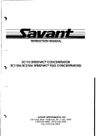
Electrical Cabling
If the bike fails to· power up when pedaled, or powers up but doesn't provide any resistance to the
pedals, the problem may be a loose or misplaced cable connection. Remove the covers from the
bike, as described on page 22, then check all connections. Tables 3-1 and 3-2 and Figures 3-1 and
3-2 show where each cable should be attached.
Connector
J4
J5
J6
J7
J1,J2
J3
Related Component
Alternator ~ mounted to the bike frame
Display board - connected to the ACB with 2 ribbon cables; 1 in the display
upright tube, 1 on the bike frame
6 volt battery - mounted to the ACB assembly RPM sensor - mounted to :the alternator
1 ohm load resistor - mounted on the side of the ACB
External power source connector - mounted on the external power plate
SmartLink Communications connector - mounted on the external power plate
Table 3-1: ACBConnectors and Related Components, ACB Rev. 10060-A
Post-October 1998 Alternator Bikes
Connector
JP1
JP2
JP3
JP5
JP6
JP7
JP8
Related Component
Alternator - mounted to the bike frame
Display board - connected to the ACB with 2 ribbon cables; 1 in the
display upright tube, 1 on the bike frame
6 volt battery - mounted to the bike frame
RPM sensor - mounted to the alternator
1 ohm load resistor: - mounted on the side of the ACB
External power source connector - mounted on the switchplate
SmartLink Communications connector - mounted on the switchplate
Table 3-2: ACB Connectors and Related Components
_. Pre-October 1998 Alternator.Bikes
If all cable connections are correct and secure, but the bike still won't power up, you may want to
continue with Appendix B, "Advanced Electrical Troubleshooting." You should perform the
procedures described there only if you are f~liar with using a volt-ohm meter and other
electrical diagnostic -procedures.
Page 13
BikeMax 1000 / 3000 Service Manual
f-
-=
--
-
\
I Polar Heart-rate
,-
Receiver (Optional)
Display Board
- --- .:""-'///']--B ~=~~~~:U~~ard
_// // // Cardia-Touch
Handgrips
Keypanel Overlay
r~
JP
L..--"t.-=-~
(Optional)
--
-.s
-4
J
\
--
External Power
Plate Assembly
Part # 61521
o
J1
t-------'
-
Display
Cable
....
CD
(1)
~
0.0
a. ocu
mE
E E
.so
>co
w_
. . - - - - - -..... J5
External
Power/Camm
External Power
to--------.
Display
ACB
Alternator Control Board
[}-[]
Part # 70418
RS-232 Communication Ports
RPM Coil
Part # 61520
Optional External Power Supply
(Wall Transformer)
Part # 13018 (110 VAC)
# 13019 (220 VAC)
~art
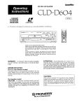
BikeMax System Block Diagram
•
= Permanent connection
D=
Plug and header
~
= Push-on terminals
Rev. 10060A ACB
@
= SCrew terminals
10-20-98 LCB
l:'8MX\TECHSERV'Bm xblock-l 0060-m onualportratt.CDR
Figure 3-1: BikeMax Electrical Connections
Post-October 1-998 Alternator Bikes
-c
~
to
(1)
i
.....L
~
~----------,
L
I'
I
(Heart-rate Receiver I
I,!
(optional)
Part #71108 • BMR
Part #71098 • BMU
.I i
I,
I.
I
I
I:
J
'------------
~
,
I
~
aQ.
J11
~~
s-~
~
External Power
Plate Assembly
~
Part #61521 • BMR
Part #61541 • BMU
.....
~
~~
OQ~
~
I
I
~~
Alternator
:
Part #61539
I
I
I
I
I
I
I
I
Alternator Control Board
~
~;:
Part #70391
I J81 RS-232
I
b:JQ
.....
;:
~
0
ACB
ss.
..,s-~
~
(---------------1
I
Display
~~
~
'
Display
Cable
~I W
I
~
Part # 50049 • BM3000
Part #50060 • BM1000
!
;::
.~ ~
..,~
Keypanel Overlay
"
(English)
Display Board
Part #61536 • BM3000
Part #61535· BM1000
RPM Sensor
RS-232 Communication Ports
~
~
Part #61520
5·
;:
Battery
_-------_ .... _-----'
.....
~
Optional External Power Supply
(Wall Transformer)
= Permanent Connection
•
Part #13018 - 11 OVAC
Part #13019 - 230VAC
(')
::J"
D
~
"'C
= Plug and Header
"*
(1)
..,
U)
~ = Push-on Terminals
Battery
Part #615"18
@
:::i
I
-I
ac::
C"
Screw Terminals
CD
C/)
::J"
o
o
"*
:5'
,.(0
j
I
(
)
I;
)
}
(
.J r.
)
(
) (
) (
)
(
)
(
)
~~
) ~
) (
)
t
)
(')
}
(,/
• ,I
(_
)
",
,
I
I.. ) ~
) ( )
I.... }
I
)"
J
I
(
,I
'
)
I
)
I
.~,
"
.
)
~.
I
)
Page 15
BikeMax 1000 / 3000 Service Manual
Isolating Mechanical Noise
The best tool for troubleshooting a mechanical noise is a long screwdriver. You can place the tip
of the screwdriver on the component to check, then rest your ear against the handle to amplify
the sound: the screwdriver works like a simple stethoscope.
The following three sections describe how to isolate the source of noise in three general areas of
the BikeMax mechanism: the crank arm area, the second stage pulley area, and the alternator.
,
{~
........
..
~---..d
You may be able to hear a mechanical noise generated in one area of the BikeMax while
listening to another area. Use the methods below to identify the source of the noise.
Mechanical Noise in the Crank Arm Area
Components include the crank arm assembly, primary pulley, 3" grooved pulley, and idler pulley.
The crank arm assembly includes the one-piece crank arm and the bearings seated in the engine
casting. The primary pulley is mounted to the crank arm assembly. The primary pulley transfers
rotational motion to the 3" grooved pulley through the primary belt. The idler pulley provides
consistent belt tension to the primary pulley and 3" grooved pulley.
If you hear a noise in the pedal or crank arm area of the bike:
1. Remove the primary belt. This
isolat~s the
primary pulley, idler pulley and crank arm.
2. Rotate the idler pulley. If it binds or wobbles, replace it as described on page 26.
3. While rotating the crank arm assembly, use the screwdriver to listen for noise in the
assembly:
•
If there is noise around the bracket that secures the engine casting to the frame of .
the bike, the bracket is loose and needs to be tightened.
•
IT there is noise in the crank arm assembly, make sure the two hex screws securing
the bearing assembly to the engine casting are tight.
•
Make sure the large collar nut and lock nut that secure the crank arm to the
bearing assembly are tight.
4. Recheck the area for noise; if noise is still present, replace the engine assembly.
5. See page 23 for instructions on replacing the primary belt.
Mechanical Noise in the Second Stage Pulley Area
Components in the second stage pulley area include the second stage pulley, pulley shaft, and 3inch diameter grooved pulley. The second stage pulley and 3-inch diameter grooved pulley are
mounted on the pulley shaft~ which rides on bearings at the rear of the engine assembly. The 3inch diameter grooved pulley receives rotational force from the primary pulley through the
primary belt. The 3-inch diameter grooved pulley drives the second stage pulley through the
pulley shaft. The second stage pulley transfers rotational motion to the alternator flywheel
through the secondary belt.
To check for problems in the second stage pulley area:
... Page 16
Chapter 3 - Troubleshooting
--~_.<--~-~ _-=------------------------------------.;...-------~
1. Remove the secondary belt that runs from the second stage pulley to the alternator
flywheel.
2. Rotate the second stage pulley.
3. While rotating the pulley, use.the screwdriver to listen for noise from:
.• The pulley shaft and bearings. If there is noise from the bearings, replace the
engine assembly
•
The area surrounding the bracket that secures the engine casting to the rear
diagonal frame member of the bike; if the bracket is loose, tighten it.
4. See page 26 for.instructions on replacing the secondary belt.
Mechanical Noise in the Alternator "Area
Alternator area components include the secopdary belt, alternator, and alternator flywheel. To
diagnose mechanical problems in the alternator area:
1. Make sure the bolts that secure the a!ternator to the frame are tight. The bolt that secures
the top of the alternator to the frame ~threads into the aluminum alternator case, so make
sure you don't strip the hole in the alternator.
2. Remove the secondary belt from the second stage pulley and alternator flywheel.
3. Make sure the flywheel is fully seated on the alternator shaft and the nut that secures the
flywheel to the shaft is tight.
4. Rotate the flywheel and use the scre~driver to listen for noise in the alternator. If noise
is present, replace the alternator.
Any alternator will make a buzzing noise when the alternator shaft is operating at high
speed. This is true for any alternator, whether it is installed in an automobile or
stationary bike.
CHAPTER 4
USING TEST MODE
The BikeMax's test mode lets you test various aspects of the bike's electrical system by pressing
the correct key and checking the resulting display. While test mode is very similar on the
BikeMax 3000 and BikeMax 1000, there are enough differences that each one has its own
section.
BikeMax 3000 Test Mode
To, enter test mode, press and hold the top HR Control key while applying power to the display
console. You can apply power either by beginning to pedal faster than 40 RPM from a stop, or by
plugging in an external power source. When you release the key, the fields at the top of the
display should show "BIKE TEST n.nn." The "n.nn" refers to the version of software installed
in the bike.
Field Indicators
The field indicators (the small red lights by "each field) provide the following information while
in test mode:
•
Elapsed Time: indicates Smart Link communications output
•
Time Remaining: indicates Smart Li~ communication input
•
Indicator
Standby
Communicating
ET
Blinking
On solid
TR
Off
On solid
Heart Rate: lights when the circuitry detects the pulse -rate transmitted by a Polar or
CardioTouch heart rate monitor.
Testing Display LEOs
If you want to test the LEDs on your display console, press one of these keys:
•
StartlEnter: Light all LEDs.
•
Top HR Control: Light vertical columns of LEDs and individual whole readouts.
•
Bottom HR Control: Light horizontal rows of LEDs and individual readout segments.
Chapter 4 - Using Test Mode
Page 18
Advanced Diagnostic Information
Press the Advanced Options key to display diagnostic information· as shown in Figure 4-1.
Power
Requested,
Watts
Power
Output,
Watts
Display
Pedal
Speed
Advanced Options
Key
Clear Key
Figure 4-1: BikeMax 3000 Test Mode Display
•
The "Elapsed Time" field indicates the feedback frequency. It should read between 1.000
KHz and 3.600 KHz; 3.60 is shown. This information is for factory use onlr; it is not
adjustable in ~he field.
•
The "Calories Burned" field shows the alternator output in volts DC. It should be at least
9.0 volts DC, as shown, when pedaling the bike at 40 to 45 RPM, with 40 watts of power
requested.
•
The "RPM" field shows the power requested by the current resistance setting. This is 40
steps of 5, by pressing the Up
Arrow or Down Arrow key. This information is for factory use only.
wattsin~FigUre-4~1:You'caii~change-"-thisamount,
in
•
The "Heart Rate" field shows the current power output of your pedaling. This can be
from 40 to 600 watts; in Figure 4-1, it is 40.
•
As you pedal, the "Speed" field shows the pedal RPM, as reported by the RPM sensor. If
this changes correctly as you speed lip or slow down, you know the sensor is working.
Figure 4-1 shows a pedal speed of 40 RPM.
Bik eM ax 10 00 / 30 00
Se rvi ce Ma nu al
Page 19
Od om et er
Yo u ca n als o rea d the
Bi ke M ax
's od om ete r in Te st Mo
de ; pre ss the Sw itc h Di
sp lay ke y to
Leaving Te st M od e
do so.
To lea ve Te st M od e, pre
ss the .C lea r ke y twice.
B ik eM ax 10 00 Te st
M od e
To en ter tes t mo de , pre
ss an d ho ld the HR Co
ntr ol key wh ile 'ap ply ing
console. Yo u ca n ap ply
po we r to the display
po we r eit he r by be gin nin
g to pe da l fas ter than 40
plu gg ing in an ex ter na
RP M from a stop, or by
l po we r source. W he n
you release the key, the
dis pla y sh ou ld sh ow '_'B
fie
lds
at the top of the
IKE TE ST n.nn." Th e "n
.nn " refers to the softw
ins tal led in the bike. are EP RO M version
Th e Te st M od e Disp
lay
W hil e yo u'r e in tes t mo
de, the co ns ole displays
the
-.
So ftw ar e
Version
information sh ow n in Fig
ure 4-2:
_F ee db ac k
Fr eq ue nc y
HR Control Key
Fi gu re 4-2 : Bi ke Ma x 10
00 Test Mode
-
~
-.
- __
. _ ..... _ .c...:lo
......
• __
-
-_....-
'_.""_"' _
_
Pedal
Sp ee d
Cl ea r Key
Display
Page 20
Chapter 4 -Using Test Mode
•
The software version displays in the "Elapsed Time" field as 'bnnn.' The 'b' indicates
BikeMaxand 'nnn' is the version number. In Figure 4-2, the version is 007. It may be
different on your bike.
•
The feedback frequency in the "Calories Burned" field should read between 3.595 and
3.605 kHz; 3.60 is shown. This infonnation is for factory use; it is not adjustable in the
field.
•
The "Speed" field shows the pedal RPM, as reported by the RPM sensor. If this changes
correctly as you speed up or slow doWll,you know the sensor is working. Figure 4-1
shows a pedal speed of 40 RPM. You can change the pedal resistance by pressing the Up
Arrow or Down Arrow key.
Heart Monitor Information
If your BikeMaxhas a Polar heart rate receiver, the field indicator (small red light) for "Heart
RatelLevel" lights if the BikeMax detects the pulse rate signal from the Polar transmitter.
Testing Display LEOs
If you want to test the LEDs on your display console, press one of these keys:
•
StartlEnter: Light all LEDs.
•
Endurance: Light vertical columns of LED segments.
•
Strength: Light individual LED segments. Press the key again for the next segment.
Leaving Test Mode
To leave Test Mode, press the Clear key twice.
CHAPTER 5
COMPONENT REPAIR AND REPLACEMENT
This chapter contains a number of individual sections. Each describes how to che~k, adjust,
and/or replace an individual component of your BikeMax. To make it easy to find any section,
each one starts on a new page. The page numbers are In the list belo\\l.
The first section describes how to remove the cover from your bike; this section is referred to by
many of the others.
Section
Cover Removal
External Power
First Stage Drive
Idler Pulley
Second Stage Drive
Engine Assembly
Alternator
RPM Sensor
Alternator Board
Battery
CardioTouch Monitor
Polar Heart Rate Monitor
Extrusion Tube
/.,.---~
..
~::
'.. ~::
t:"J
~"
'::.>
. . .- --d
Page
22
23
24
26
26
29
32
35
38
39
40
43
45
Before beginning any procedure, please carefully read the entire instructions for it.
'~T
._,._._._-.-,
_'._
<_P_a~g_e_2_2
C_h_a..;..p_te_r_5_-_C_o_m.....;.p_o_n_e_nt_R_e.....;.p_a_ir_a_n_d_R_e_p_'a_c_e_m_e_n_t
Cover Removal
.
.
1. If the bike is equipped with the optionalAC adapter, unplug the adapter from the bike.
2. On the upright BikeMax only, you·m~st detach the seat bellows from the cover before
removing the ~over. Raise the seat as high as it will go. Grasp the rubber accordion
bellows and gently pull upward to unsnap it from the plastic bike cov~r. 3. Remove the ten Phillips-head screw~ tnat secure the cover halves to the bike frame.
to
4. Rotate the right (as if you were sitting on the bike) crank. arm the 12 o'clock position.
Grasp the bottom of the right cover half and pull it away from the frame. Gently lift the
cover over the crank arm and off the bike.
5. Rotate the left crank. arm to the 12 o'clock position and remove the left cover half.To replace the covers, perform these steps in reverse order.
BikeMax 1000 / 3000 Service Manual
Page 23
External Power Supply
The optional external power adaptor can be very useful as a troubleshooting tool. It allows easy
recharging of the battery, and makes Test Mode easier to use.
The table below gives the part numbers and descriptions of the AC adapters available from
Tectrix.
Tectrix Part Number
13018
13019
Description
Adapter, 110 VAC input, 10 VAC output
Adapter, 230 VAC input, 10 VAC output
Plug the AC adapter into the circular connector on the switchplate. The switchplate is located at
the front of the bike, above the stationary axle.
Chapter 5 - Component Repair and Replacement
Page 24
First Stage Drive
Tools Needed:
9/16" socket and wrench
Flat-blade screwdriver
9/16" -open-end wrench
#2 PlJ,illips screwdriver
The 13" primary pulley, which is attached to-the pedal crank arm, begins the transfer of pedaling
power to the dri~e engine of the bike.-It turns the IO-groove primary belt, which-turns the 3"
grooved pulley. This assembly, which includes other parts,-is called the "frrst stage drive." This
section describes how to remove and replacei the primary be~t, and how to adjust the belt's
tension.
Important: Proper primary belt tension is set at the factory. If you ne~d to remove and
replace the belt, you should normally:do so without relaxing the tension on the belt. If you
.do need to change the tension, see the instructions below.
Adjustment bolt
Pivot bolt
Primary
pulley
3" grooved
pulley
Idler pulley
Figure 5-1: First Stage Drive Components
~............,,:~........-..-..,.,..,-~----....
T_..--.~_r_em_o_v~e~an~":~l?lac~ the p~mary belt:
1. IT the bike is equipped with the optional external power adapter, unplug the adapter from
the bike.
2. Remove the bike covers. See page 2~.
3. Rotate the primary pulley clockwise -and carefully move the primary belt off the outside
edges of the primary pUlley, idler pulley, and 3" grooved pulley.
BikeMax 1000 / 3000 Service Manual
Page 25
4. Loop the new belt around the idler and 3" grooved pulleys first, as shown in Figure 5-1,
then wrap the belt around the primary pulley while rotating the primary pulley counterclockwise to pull the belt up onto the surface. Make sure the belt is centered in the
grooves on all the pulleys.
5. Replace the bike covers. See page 22.
To change tension on the primary belt:
1. If the bike is equipped with the optional external power adapter, unplug the adapter from
the bike.
2. Remove the bike covers. See page 22.
3. Loosen the idler arm pivot bolt, located behind the primary pulley. Some BikeMax
models have a hole in the primary pulley to make access to this bolt easier, as shown in
Figure 5-1.
4. Loosen the idler arm adjustment bolt, located just above the idler pulley.
5. Place the flat-blade screwdriver in idler pulley adjustment slot, above the adjustment
bolt. Make sure the blade of the screwdriver rests on the engine casting.
6. Carefully move the idler arm upward to apply tension to the belt. Apply tension so the
belt is tight, but not so tight that the idler pulley is distorted sideways.
7. Hold the screwdriver in place and tighten the adjustment bolt, then tighten the pivot bolt.
8. Rotate the crank arm to ensure the belt is tracking in the center of the primary pulley and
3" groo~ed pulley.
9. Replace the bike covers. See page 22.
Chapter 5 - Component Repair and Replacement
Page 26
Idler Pulley
The idler pulley is part of the first stage drive; it maintains constant tension on the primary belt.
The primary belt transfers pedal motion to the 3" grooved pulley and idler pulley. If the bushing
inside the idler pulley is worn, the pulley will start to wobble and the primary belt can slip off the
three pulleys.
Tools Needed:
9116" socket and wrench
.Flat-blade screwdriver
9116" box-end or open-end wrench
'Please refer to Figure 5-1 on page 24 for the location of the first stage drive components
referred to below.
To remove the idler pulley:
1. If the optional ACtransformer is installed, unplug it from the bike.
2. Remove the bike covers. See page 22.
3.. Loosen the idler bracket pivot bolt, located behind the primary pulley.
4. Place the flat-blade screwdriver in the adjustment slot of the idler bracket, above the
adjustment bolt. Rest the tip of the screwdriver on the engine casting.
5. Loosen the idler bracket adjustment bolt and let the bracket rest against the shaft of the
screwdriver. Slowly remove the screwdriver from the adjustment slot.
6. Rotate the primary pulley counter-clockwise and remove the primary belt from the
primary pulley, 3" grooved pulley, and idler pulley.
7. Remove the bolt, washer, and nut th~t secure the idler pulley to the idler pulley bracke~..
8. Remove the idler pulley.
To install the idler pulley:
The idler pulley comes with the bushing pre-installed by the factory. The bushing is
exposed on the back side of the pulley. The mounting bolt and washer are installed
through the front side of the pulley.
1. Install the bolt and washer through tJ:1e idler pulley.
2. Place the idler pulley against the idler pulley bracket, so the bushing contacts the bracket.
3~ ~1nsta1tthenfit on
the-bolt-and tighten -menut.-Spin the idler pulley and verify that it does
not bind on the bushing.
4. Install the primary belt and adjust the belt tension. See page 24.
5. Replace the bike covers. See page 22.
---.,.---,..-_.-
------
-.-
------~-~-----,
--_ .. _---.....
~-~~-~
-- -_.-
r
Page 27
Man ual
Bike Max 100 0 I 300 0 Serv ice
Second St ag e Drive
ugh the secondary belt.
ped alin g pow er to the alte rnat or thro
The 13" sec ond ary pul ley applies
, adju st the belt tension, and
ove and repl ace the seco nda ry belt
rem
to
how
es
crib
des
tion
sec
s
Thi
and 3" grooved pulley).
y (secondary pull ey, pull ey shaft,
mbl
asse
e
stag
ond
sec
re
enti
the
rep lace
lt
Re pla cin g the Se con dar y Be
the bike.
AC ada pter , unp lug the adapter from
l
ona
opti
the
with
ed
ipp
equ
is
e
1. If the bik
e 22.
2. Rem ove the bik e covers. See pag
ey on the left side of the bike.
3. Slo wly rota te the secondary pull
the pulley.
outs ide edg e of the pulley, then off
4. Car efu lly mov e the belt to the
from the sma ll alte rnat or pull ey.
5. Rem ove the rem aind er of the belt
nd the secondary
nd the altemat<;>r pulley, then arou
arou
it
ing
loop
by
belt
new
the
6. Inst all
ey in eith er direction.
pul ley as you slow ly tum the pull
on both pulleys.
7. Ma ke sure the belt is cen tere d
e 22.
8. Rep lace the bik e covers. See pag
relaxing the
repl ace the seco nda ry belt with out
Imp orta nt: You sho uld rem ove and
ally remain
is set at the fact ory and sho uld norm
tens ion on the belt. Pro per tens ion
w.
the tension, see the instructions belo
corr ect. If you do nee d to cha nge
.
Adjusting the Se con dar y Belt
Too ls Nee ded :
%" box -en d or ope n-e nd wre nch
Fla t-bl ade scre wdr iver
wre nch
~" box -en d or ope n-e nd
-%" Soc ket wrench
#2 Phi llip s scre wdr iver
pter from the bike.
optional AC adapter, unp lug the ada
1. If the bik e is equ ipp ed with the
e 22.
2. Rem ove the. bik e covers. See pag
bracket.
the alternator to the slot ted fram e
3. Loo sen the Yz" bol t that secures
bracket.
secure the alte rnat or to the fram e
4. Loo sen the %" bol t and nut that
essary to apply
e the alte rnat or in the dire ctio n nec
5. Usi ng you r han ds, carefully mov
tens ion to the seco nda ry belt.
to stop mov eme nt
ry belt pro vide s eno ugh resi stan ce
nda
seco
the
from
ion
tens
the
en
6. Wh
bol t or you may
stm ent bolt. Do not ove rtig hten the
of the alte rnat or, tighten the Y2" adju
tor.
stri p the thre ade d hol e in the alterna
7. Tig hten the %" piv ot bol t and nut.
-
and Replacement
Chapter 5 - Component Repair
.' Page 28
and
8. Rot ate the sec ond stag e pul ley
eith er pulley.
9. Ver ify the
al~gnment of the
the edges of
mak e sure the belt does not overlap
page 35.
RPM sen sor to the alternator. See
e 22.
IO.Replace the bik e covers. See pag
Assembly
Replacing the Second Stage
Tools Needed:
Flat-blade scre wdr iver
or install the engine
stag e assembly in order to remove
You may nee d to rem ove .the sec ond
ry pulley, pull ey shaft,
nda
stag e assembly includes the seco
asse mbl y into the bike. The sec ond
and 3" gro ove d pulley.
pter from the bike.
optional AC adapter, unplug the ada
the
h
wit
ed
ipp
equ
is
e
bik
the
If
1.
e 22.
2. Rem ove the bik e covers. See pag
e 27).
e ~4 and the secondary belt (see pag
3. Rem ove the prim ary belt (see pag
not unscrew.
second stage pulley with a nut. Do
The pull ey sha ft is.a ttac hed to the
the shaft.
you are replacing the pulley and not
the pulley sha ft from the nut unle ss
secures the 3"
, carefully pry up on the c-clip that
3. Usi ng the flat-blade scre wdr iver
gro ove d pull ey to the pul ley shaft.
ey. Slid e the pulley
outs:ide edge of the 3" grooved pull
4. Rem ove the two was her s on the
.
off the pull ey shaft.
hers from the pulley shaft.
5. Rem ove the rem aini ng two was
bearings in the eng ine
e pull ey and pulley shaft out of the
6. Car eful ly slid e the sec ond stag
casting.
ring s of the
e pull ey and pulley shaft into the bea
stag
ond
sec
new
the
e
slid
ly
eful
7. Car
eng ine casting.
shaft.
8. Pla ce two washers on the pul ley
go on so it will
the pull ey shaft. The pulley should
9. Install the 3" gro ove d pul ley on
t side of the bik e
righ
the
ctio n when viewed from
dire
ise
ckw
-clo
nter
cou
a
in
el
freewhe
the bike frame.
on the .hub of the pulley goes tow ard
(the side it's on). The sma ll arro w
c-clip on the pulley shaft.
rO: lilsf allt ne oijier"two wasliers ana
s not, repl ace the
tes freely in the bearings. If it doe
II.M ake sure the pull ey sha ft rota
eng ine (see pag e 29).
be~ts. See pages 24 and 27.
I2.Inst.all the prim ary and sec ond ary
e 22.
I3.R epla ce the bik e covers. See pag
~~.~-~-- ."~-.-.--
----~--~-
BikeMa x 1000 I 3000 Service Manual
Page 29
Engine Assembly
Tools Needed:
#2 Phillips Screwdriver
~" Socket and wrench
~"
box-en d or open-end wrench
The main engine assemb ly is the connection between the moving compo
nents and the frame of
the bike. If replace ment is necessary, a complete assembly, including
the engine casting, primary,
secondary, idler, and 3" groove d pulleys, and. bearings is available.
Follow the procedures below
to remove and replace the engine assembly..
The engine assemb ly is bulky and can be awkwa rd to maneu ver in and
out of the bike
frame. Be very careful to avoid injury during the replacement.
For your referen ce, there is an explod ed view of the engine assembly
at the end of this section.
Removing the Engin e Assembly
1. H the bike is equipp ed with the optional AC adapter, unplug the
adapte r from the bike.
2. Remov e the bike covers. See page 22.
3. Remov e the second ary belt:
• Slowly rotate the secondary pulley on the left side of the bike.
• Carefu lly move the belt to the outside edge of the pulley, then off
the pulley.
• Remov e the remain der of the belt from the small alterna tor pulley.
4. Remov e the pedal and cover plate from the left side of the bike.
• Remov e the pedal from the left crank arm.
•
Remov e the three Phillips screws from the cover plate that surrounds
the left crank
arm.
•
Remov e the cover plate from ~he bike.
5. On a recumb ent BikeM ax, you may need to remove the primar y
belt, then remove the 3"
groove d pulley, pulley shaft, and secondary pulley before removi ng
the engine. If you
need to do this, see "Repla cing the Second Stage Assembly" on page
28.
6. Remov e the two Y2" bolts and washers from the brass-colored mounti
ng plate that secures
the front of the engine casting to the .semi-circular frame m<?unting
bracket.
7. Remov e.the four Phillip s screws that hold the brass-c olored rear
engine mounting plate
to the right side of the bike frame. Remove the mounti ng plate.
During the next step, you must suppor t the rear of the engine assemb
ly before
you remove the second Y2" bolt that secures the engine to the bike frame.
8. Remov e the two
frame.
~"
bolts and nuts that secure the rear of the engine casting to the bike
- - -- ...-.---_ - ,'---- ----_... _ - - ---"'--- _.- _----- ---- _---,.- ------ - --...
..
...
Chapter 5 - Component Repair and Replacement
Page "30
9. Rotate the right crank'arm so it points toward the rear of the bike. ,While supporting the
front of the engine casting, carefully rock the rear of the engine assembly, toward the top
of the diagonal frame member. The front of the casting will drop away from its semicircular frame mounting bracket.
IO.When the engine assembly is free within the frame, remove it from the.left side of the
frame.
Installing the New Engine Assembly
With a recumbent bike, you must rotate the right crank arm so it points to the rear of the
bike before you start the installation~For an upright bike, the left crank arm must point
toward the rear of the bike.
1. From the left side of the bike, place ~he primary (crank arm) pulley and engine assembIy
through the frame and toward the front of the bike. Rotate the casting so the rear of the
casting can be seated into the center of the diagonal frame meIp.ber.
2. Lift the front of the engine assembly and position the casting into the semi-circular frame
mounting bracket. Insert the two ~" polts and washers through the brass-colored
mounting plate and into the frame. Do not tighten the bolts yet.
3'. Place a ~" bolt and washer through the rear engine mounting plate. Lift the rear of the
engine casting and align the holes in ,the casting with the holes in the frame. Insert the
bolt through the casting and bike frame so the plate is properly positioned on the frame.
Insert the second Y2" mounting bolt and washer through the mounting plate, casting, and
bike frame.
4. Install the four Phillips screws through the mounting plate into the diagonal frame
member. Do not tighten the screws yet.
5. Install the two nuts on the two rear ~" bolts. D.o not tighten the nuts and bolts yet.
6. Tighten the front two Y2" bolts at an even rate, so the mounting plate is fully seated
.against its mounting surface ~n the s¢mi-circular frame bracket.
7. Tighten the four Phillips screws to secure the rear.~ounting plate to the frame.
8. Tighten the two
~"
bolts and nuts to;secure the rear of the engine casting to the frame.
9. Install the secondary belt as described in
"R~placing the
Secondary Belt" on page 27.
IO.Install the cover plate and pedal as listed in Step 3, in reverse order.
~""""'-""'~~~"-"-------""""~;+he-new-engine·-is~now-installed-;-Before-replacingthe covers, test the bike to make sure it's
operating properly:
1. IT the bike has the optional external power supply, plug it into the switchplate.
2. Pedal the b~e and make sure you can enter various program modes. If the bike does not
have an external power supply, you must pedal at least 40 RPM. Make sure the
resistance increases when you press the Up .Arrow is pressed, and decreases when you
press the Down Arrow.
BikeMax 1000 / 3000 Service Manual
Page 31
3. If the bike has a CardioTouch heart-rate sensor, pedal the bike and place your hands on
the rubber-coated CardioTouch grips. The bike should sense your heart-rate and display
a flashipg shield in the upper right of the display. Your heart-rate should appear on the
console within 30 seconds.
4. If the bike has a Polar heart-rate sensor, use a Polar chest strap or Polar test transmitter.
The bike should sense your heart-rate and display a flashing shield in the upper right of
the display. Your heart-rate should appear on the console within 30 seconds.
5. If either heart rate sensor is not working, make sl:lre all cables are attached securely.
Once you know the bike is working correctly, unplug the external power supply (if it has one),
and replace the covers. See page 22.
Page 32
Chapter 5 - Component Repair and Replacement
Alternator
Tools Needed:
#2 Phillips screwdriver
Flat blade screwdriver
3/4" socket and wrench
~" box-end or open-end wrench
3/4" box-end or open-end wrench
7/8" socket
The alternator. provides the pedaling resistance the rider feels. The pulley which connects the
alternator with the secondary belt also functi~ns as a flywheel and RPM sensor encoder.
Removing the Alternator
1. If the bike is equipped with the optional AC adapter, unplug the adapter from the bike.
2. Remove the bike covers. See page 22.
3. Remove the secondary belt:
•
Slowly rotate the secondary pulley on the left side of the bike.
•
Carefully move the belt to the outside edge of the pulley, then off the pulley.
•
Remove the remainder of the belt from the small alternator pulley.
4. Remove the RPM sensor from the alternator case:
~"
•
Remove the
•
Move the sensor away from the area surrounding the alternator.
bolt and washer that secures the sensor to the alternator.
5. Carefully insert a flat-blade screwdriver through one of the six openings in the alternator
pulley and rest the tip against the housing. This will keep the pulley from moving.
6. Loosen and remove the 7/8" retaining nut and washer from the alternator s~aft.
7. Carefully remove the alternator pulley from the alternator shaft.
Do not lose the half-moon shaped key that fits into the alternator shaft; the key prevents
the pulley from spinning freely on the shaft.
8. Unplug the alternator cable from connector JPI on the Alternator Control Board (ACB).
9. Do one of the following, depending on the bike model:
•
Recumbent: Unclip and remove the alternator cable from the bottom of the
extrusion tube.
". 'UprighI:-Uticlip "arloreinove· tlie· alternator cable from the right side of the diagonal
frame member.
IO.Before removing the alternator, you may want to mark its location on the belt tension
adjustment slot. This will make it easier to install the new alternator in the correct
position.
II.Loosen the
~"
bolt that secures the alternator to the slotted frame bracket.
Page 33
BikeMax 1000 / 3000 Service Manual
12.Support the alternator in place and remove the~" bolt from the slotted frame bracket.
WARNING:
To avoid personal injury, you need to support the alternator on the BMR before you
remove the %" bolt securing the alternator to the frame bracket.
13.Remove the %" bolt and nut that secUre the alternator to the frame bracket.
I4.Remove the alternator from the frame.
Installing the New Alternator
Essentially, installing the new alternator is the same as removing the old one, in reverse:
1. Place the alternator in position.
2. Insert the %" bolt and nut that secure the alternator to the frame bracket.
3. Insert the ~" bolt and washer into the slotted frame bracket,and carefully thread it into
the mounting hole in the alternator.
4. If you marked the old alternator's position on the belt tension adjustment slot, place the
alternator in the same position, so the secondary belt tension will be correct. Tighten the
Y2" bolt that secures the alternator to the slotted frame bracket. Tighten the %" bolt and
nut that secure the alternator to the frame bracket.
5. Do one of the following, depending on the bike model:
•
Recumbent: Clip the alternator cable to the bottom of the extrusion tube.
•
Upright: Clip the alternator cable to the right side of the diagonal frame. member.
6. Plug the alternator cable into connector JPI on the Alternator Control Board (ACB).
7. Carefully place the flywheel on the alternator shaft. Make sure the half-moon key on the
alternator shaft fits into the notch on the flywheel.
8. Install the washer and 7/8" retaining nut on the alternator shaft.
9. Carefully insert a flat-blade screwdriver through one of the six openings in the alternator
pulley and rest the tip agains~ the housing. This will keep the pulley from moving.
Tighten the 7/8" retaining nut.
IO.Place the RPM sens.or in position and insert and tighten the~" bolt and washer that
secures the sensor to the alternator.
II.Adjust the RPM Sensor, as described on page 35.
12.Install the secondary belt as described on page 27. If necessary,
as shown in that section.
~djust the
belt's tension
The new engine is now installed. Before replacing the covers, test the bike to make sure it's
operating properly:
1. If the bike has the optional external power supply, plug it into the switchplate.
Page 34
Chapter 5 - Component Repair and Replacement
2. Pedal the bike and make sure you can enter various program modes. If the bike does not
have an external power supply, you must pedal at least 40 RPM. Make sure the
resistance increases when you press ~he Up Arrow, and decreases when you press the
Down Arrow.
3. If the bike has a CardioTouch heart-rate sensor, pedal the bike and place your hands on
the rubber-coated CardioTouch grips. The bike should sense your heart-rate and display
a flashing shield in the upper right of the display. Your heart-rate should appear on the
console within 30 seconds.
4. If the bike has a Polar heart-rate sensor, use a Polar chest strap or Polar test transmitter.
The bike should sense your heart-rate and display a flashing shield in the upper right of
the display. Your heart-rate should appear on the console within 30 seconds.
5. If either heart-rate sensor is not working, make sure all cables are attached securely.
Once you know the bike is working correctly, unplug the external power supply (if it has one),
and replace the covers. See page 22.
BikeMax 1000 I 3000 Service Manual
Page 35
RPM Sensor
#2 Phillips screwdriver
Tools Needed:
1/2" box-e'nd wrench
Feeler gauges, standard
or metric
The RPM sensor must be adjusted properly near the metal alternator flywheel. The edge of the
flywh~el must pass over the metal center part of the sensor, and the gap between the sensor and
the flywheel must be between 0.020 and 0.060 inches. To adjust the RPM sensor:
1. If the bike is equipped with the optional AC adapter, unplug the adapter from the bike.
2. Remove the bike covers. See page 22.
3. Loosen the 1/2" bolt that secures the RPM sensor to the alternator.
4. Look at the face of the flywheel and ~M sensor. Position the sensor so one-half of the
sensor's center core is covered by the flywheel, as shown in the drawing below.
~-~
/
""",,-
"
/
~'\
Coil
/1 / ' magne-t
-J....
/1
,.
\
'-\......
\
/
RPM Coil
\
("l
\" ,)
\......:
(
\
~'--'"
"
1.. _... '\
I
\\
.
---
I
!
\
I
\
.
~
\
)
I
/
//
~~\
Flywheel
Alignment of RPM Coil with Flywheel
On Tectrix Alternator BikeMax
-.
_ _ _ _ ..
,
.
0- _ _
Page 36
Chapter 5 - Component Repair and Replacement
1/2" bolt
Sensor coverage
4. Tighten the 1/2" ·bolt. "Do not overtighten the bolt, or you may strip the threaded hole
in the alternator.
5. Verify the air gap between the sensor and the flywheel:
• Check the bracket to make sure the RPM sensor coil is not bent into or away from
the flywheel.
•
Check the air gap between the center core of the RPM sensor and the back of the
flywheel. The air gap should be in a range of .020" to .060", or .5mrn to 1.5mm.
If necessary, carefully bend the sensor bracket to achieve the desired air gap. See
the picture below.
Sensor gap
6. Test the RPM sensor.
BikeMax 1000 / 3000 Service Manual
Page 37
•
Press and hold the top HR Control button on the console.
•
Pedal the bike at 40 RPM or greater to activate the console, or plug in the optional
AC adapter.
•
Verify that the "Speed" field on the console indicates your pedal speed. IT the
value is zero or non-existent, make sure the RPM sensor is plugged into connector
JP5 on the Alternator Control-Board (ACB). If the value is still zero or nonexistent, replace the RPM sensor.
7. Replace the bike covers. See page 22.
Page 38
Chapter 5 - Component Repair and Replacement
Alternator Control Board
Tools Needed:
-#2 Phillips screwdriver
You may need to replace the Alternator Control Bo.ard (ACB) if the electrical troubleshooting
procedure in Chapter 3 recommends it, or if the group race feature is not working for a set of
linked bikes. Discrepancies in the bikes' ACBs can keep group racing from working. If this is the
case, you should replace the ACB on each linked bike.
To replace the ACB:
1. If the bike is equipped with the optional AC adapter, unplug the adapter from the bike.
2. Remove. the bike covers. See page 22.
3. Disconnect the electrical cables from connectors JP3, I4P, JP5, and IP7.
4. Remove the ACB assembly fromthe frame by unscrewing the two Phillips-head screws.
5. Attach the new ACB assembly to the frame.
6. Reconnect the leads. If you need to, refer to Tables 3-1 and 3-2 or Figures 3-1 and 3-2.
7. Replace the bike cover. See p~ge 22.
Page 39
BikeMax 1000 I 3000 Service Manual
Battery
Tools Needed:
#2 Phillips screwdriver
Optional AC adapter (if
available)
Volt-ohm meter with test leads
The battery must be functional in- order to activate the bike. A fully charged battery will have 6.0
to 6.3 VDC present when it is plugged into connector J6 (Rev. 10060A) or JP3 (Rev. 10050A) on
the ACB.
To test the battery:
1. Remove the bike covers. See page 22.
2. Verify that the.battery is plugged into the ACB.
3. Set the volt-ohm meter to sense DC volts, using the 20 volt scale (if the meter has this
setting available). Make sure the red lead is connected to the VDC connector on the
meter and the black lead is connected to the GND connector on the meter.
4. Connect the black meter lead (from the GND connector) to the black wire on connector
J6.
5. Connect the red meter lead (from the- VDC connector) to the white wire on connector J6.
6. A fully charged battery will indicate 6.0 to 6.3 VDC. A battery with less than 5.7 VDC
will not activate the bike. The technician or customer can attempt to charge the battery
with the optional AC adapter.
If the AC adapter is available, plug the adapter into the circular connector on the switchplate.
The adapter will charge the battery in approximately 2 hours, but the bike may be used at once,
while charging.
Chapter 5 ;,. Component Repair and Replacement
Page 40
CardioTouch Heart Rate Receiver
Tools Needed:
#2 Phillips screwdriver
Optional!1C adapter (if
available)
Volt-ohm meter with test leads
3116" hex wrench
CT heart rate detection uses special rubber hand grips to sense the heart rate. The heart rate
signal is transmitted through electrical cablirig to a CT circuit board mounted on the display
board in the console. The user must keep botQhands on the rubber hand grips during the workout
so CT can consistently detect the heart rate. On the recumbent bike, the rubber hand grips are
mounteq to handlebars on each side of the seat. On the upright bike, the hand grips are on a
balance bar directly below the console.
The most common cause of an inconsistent or non-existent readout is that the user does not have
hislher hands on the hand-grips, or that the grips are covered with perspiration. The first thing to
do if you have trouble with GT heart rate readout is clean the hand grips with alcohol to remove
built-up perspiration and other dirt.
If cleaning the grips does not fix the problem, you need to examine the individual components of
the CT system. Besides the hand grips, the system includes: a cable that terminates at a connector
(under the back of the seat on the recumbent.bike, outside the balance bar on the upright);
extrusion tube and upright tube cables (recurp.bent bike only), and the CT circuit board.
The CT cable is a 2-conductor cable. The end of the cable that connects to the CT board
has a brown, 4-pin connector.
The key to troubleshooting CT is to isolate each component, and test each component
independent of the other components. The test process requires the use of a volt-ohm meter, and
can involve partial disassembly of the bike. .
The most common cause of failure with CT is due to a pinched or disconnected cable at the
console or in the display upright tube. To check for this problem:
1. Remove the console and verify that the CT board is installed onto the display board.
2. Make sure the 4-pin connector on the CT cable i.s plugged into the 4-pin connector on the
CT board. (Refer to the system block diagram.)
3. Make sure the CT cable-is not pinched or cut where it exits the top of the display upright
tube.
4. Make sure the wires are not separated from the 4-pin connector.
If the CT board is installed and the cable integrity and installation is correct, test the CT system
as follows:
-
1. Plug the AC adapter (if available) into the bike, or pedal the bike to activate the console.
2. Place your hands on the CT rubber hand grips.
Page 41
BikeMax 1000 / 3000 Service Manual
3. IT CT is operating correctly, a flashing indicator will appear in the top right corner of the
display. This indicates that CT has sensed your heart rate.
4. Within 30 seconds, a digital readout of your heart rate will display.
If the flashing indicator doesn't appear, or if it does appear, but your heart rate doesn't display,
replace the CT circuit board and test CT again. If a new CT board does not correct the problem,
troubleshoot the problem as described below. There are different procedures for the recumbent
and upright bikes.
Recumbent Bike CardioTouch Troubleshooting
1. If the AC adapter is installed, unplug it from the bike.
2. Unplug the 4-pin connector cable from the CT board.
3. Set the volt-ohm meter to the 200 ohms setting. Place one meter lead on one of the CT
rubber hand grips, and the other meter lead on one of the wires in the 4-pin connector.
One wire in the connector is dedicated to each hand grip, so observe the meter for
continuity (a change in the numeric display or needle movement). If continuity is
present, the connection between that hand grip and the connector is good. Verify the
same for the other hand grip and wire in the connector.
If either wire or hand grip fails the continuity test (no needle movement or change in the
numeric display), the problem is in one of the CT components. To detennine which one,
you will check ~he connections and continuity of the CT cables in the display upright and
extrusion tube, and the flex cable that connects the extrusion tube cable to the seat
shuttle.
4. Unbolt and remove the display upright tube from the base. Carefully hold the tube and
verify that the 2-conductor cable from the extrusion tube is plugged into the 2-conductor
cable that connects to the CT board in the console. If the cables are connected,
disconnect them and repeat the continuity test for each hand grip and wire within the 2conductor cable exiting the front of the extrusion tube.
If the hand grips and 2-conductor cable in the extrusion tube pass the con~inuity test, then
the 2-conductor cable in the upright tube is defective. Replace the cable and test CT
again.
5. If the continuity test fails, remove the seat shuttle, 2-conductor CT extrusion tube cable,
and flex cable (refer to "Extrusion Tube Removal and Installation: BikeMax-R Only on
page 45). Perform continuity tests on the 2-conductor CT extrusion tube cable and flex
cable independently of each other. 1
-
If either cable fails the continuity test, replace it and test CT again.
6. If both the CT cable and flex cable pass the continuity test, then test continuity between
the hand grips and the connector on the bottom of the seat shuttle.
If a hand grip and a wire in the connector on the bottom of the seat shuttle fail the
continuity test, replace the seat shuttle and test CT again.
Page 42
Chapter 5 - Component Repair and Replacement
7. Once the diagnosis and repairs are complete, test CT again to verify integrity of the CT
system.
Upright Bike CardioTouch Troubleshooting
1. IT the AC adapter is installed, unplug it from the bike.
2. Unplug the 4-pin connector cable from the CT board.
3. Set the volt-ohm meter to the 200 oh!JlS setting. Place one meter lead on one of the CT
rubber hand grips, and the other meter lead on one of the wires in the 4-pin connector.
One wire in the connector is dedicated to each hand grip, so observe the meter for
continuity (a change in the numeric q.isplay or needle movement). If continuity is
present, the connection between that-hand grip and the connector is good. Verify the
same for the other hand grip and wire in the connector.
If either hand grip or wire in the balance bar fails the continuity test, the CT balance bar
is defective and must be replaced.
4. Replace the defective CT balance bar and test CT again to verify integrity of the CT
system.
Page 43
BikeMax 1000 I 3000 Service Manual
Polar Heart Rate Receiver
Tools Needed:
#2 Phillips screwdriver
3116" hex wrench
112" open-end wrench
. Polar heart rate detection uses a chest strap that detects the heart rate and transmits it to a
receiver module. Depending .of the type of BikeMax, the receiver is connected to the display
board with one or two 3-conductor electrical cable(s):
•
On the recumbent bike, the receiver module is inside the extrusion tube at the back of the
bike. It is connected to a 3-conductor cable in the extrusion tube, which exits at the front
of the tube. A second 3-conductor cable connects to the cable at the front of the
extrusion tube, and carries the heart rate signal to the display board in the console.
•
On the upright bike, the receiver module is mounted on the display upright tube below
the console.
On both bikes, the end of the Polar cable that connects to the display board has a brown, 3conductor connector.
On the upright bike, the Polar cable has a white label at one end. The labeled end of the
cable plugs into the Polar receiver module.
If the Polar display indicates an erratic heart rate, verify the positioning of the ribbon and Polar
cables under the console. The cables should be kept separate from one another, and excess
cabling should be within the upright tube.
If no heart rate value is displayed, make sure the Polar cable is plugged into the 3-conductor male
connector on the display board. Verify the operation of the Polar chest strap by testing the
receiver with another chest strap, or with a Polar test transmitter. If possible, swap the receiver
module and test Polar again.
If the -heart rate is still not displayed, troubleshoot the problem as described below. There are
different procedures for the recumbent and upright bikes.
Recumbent Bike Polar Troubleshooting
1. If the AC adapter is installed, unplug it from the bike.
2. Unplugthe 3-conductor connector from the display board.
3. Remove the end cap from the back of the extrusion tube, loosen the ~rr nut and hex
screw, and remove the Polar receiver. Unplug the receiver from the 3-conductor cable,
and carefully pull about 2 inches of the cable out of the tube.
4. Set the volt-ohm meter to the 200 ohms setting. Place one meter lead on one of the wires
in the 3-cond~ctor connector at the top of the display upright tube. Place the other meter
lead on one of the wires in the 3-conductor cable at the end of the extrusion tube.
Chapter 5 - Component Repair and Replacement
Page 44
Observe the meter for continuity zero ohms, or a low ohms reading, 10- or less. If
continuity is present, verify the sam~ for the other wire in the cables.
If either wire within the cables fails the continuity test, there is probably a disconnected
cable or broken wire within a cable. You need to verify good connections and continuity
of the Polar cables in the display upright and extrusion tube.
5. Unbolt aJ:ld remove the display upright tube from the base. Carefully.hold the tube and
verify that the 3-conductor cable from the extrusion tube is plugged into the 3-conductor
cable that connects to the display board in the console. If the cables are connected,
disconnect them. Repeat the continuity test on each wire of the 3-conductor cable in the
extrusion tube.
extru~ion tube passes the continuity test, then the 3conductor cable in the upright tube is defective. Replace the cable and test Polar again.
If the 3-conductor cable in the
IT the 3-conductor cable in the extrusion tube fails the continuity test, replace it and test
Polar again.
6. IT the problem still exists, replace the display board.
7. Once the diagnosis and repairs are complete, test Polar again to verify integrity of the
Polar system.
Upright Bike Polar Troubleshooting
1. IT the AC adapter is installed, unplug it from the bike.
2. Unplug the 3-conductor connector from the display board.
3. Unscrew and remove the Polar receiver module from the display upright tube.
Disconnect the 3-conductor connector from the receiver module.
4. Set the volt-ohm meter to the 200 ohm setting. Place one meter lead on one of the wires
in the 3-conductor connector at the t~p of the display upright tube. Place the other meter
lead on the same wire in the 3-conductor cable at the other end of the cable. Observe the
meter for continuity zero ohms, or a 'low ohms reading, 10· or less. IT continuity is
present for the fITst wire, verify the ~ame for the other wire.
5. If either wire in the cable fails the continuity test, replace the cable and test the Polar
system for proper heart rate detection and display.
6. If the problem still exists, or if the cable passes the continuity test, replace the display
board.
7. 'Once the proper diagnosis and repairs are complete, test Polar again to verify integrlty of
the Polar system.
Page 45
BikeMax 1000 I 3000 Service Manual
Extrusion Tube Re-moval and Installation: BikeMax-R Only
Tools Needed:
#2 Phillips screwdriver
~" box-end or open-end
wrench
1 " piece of Scotch tape
3116" hex (Allen) wrench
~" socket and wrench
This section also includes the removal and installation of the seat shuttle assembly.
1. If the bike is equipped with the optional AC adapter, unplug the adapter from the bike.
2. Remove the rectangular end cap from the rear of the extrusion tube by removing the four
-Phillips screws that secure it.
3. Remove the seat shuttle from the bike:
•
Remove the 3/16" hex screw and its lh" nut from the right rear comer of the
extrusion tube. If the bike is equipped with a Polar receiver, remove the receiver
from the tube.
•
Phillips screws on either side at the front of the seat shuttle secure a brake plate.
Remove the two Phillips screws and the brake plate from the shuttle.
•
Lift the blue locking handle of the seat shuttle, and carefully slide the seat shuttle
to the rear-most position of the extrusion tube.
•
If the bike is equipped with CardioTouch, unplug the flex cable from the
connector located on the bottom of the rear-most location on the seat shuttle.
•
Carefully slide the seat shuttle off the extrusion tube.
4. Remove the covers from the bike. See page 22.
5. Remove the Alternator Control Board (ACB) and load resistor:
•
Unplug all electrical connectors from the ACB except connector JP6: this cable
connects the load resistor to the ACB.
•
Remove the two Phillips screws that secure the ACB and resistor to the frame and
remove the ACB and resistor.
6. Remove the extrusion tube from the bike.
•
Two bolts on the underside of the extrusion tube secure it to the frame. These
bolts are secured to a removable, threaded retainer. Note the position of the
retainer within the tube. Then, using the Y2" socket and wrench, remove the front
bolt, then the rear one.
•
While the tube is still positioned on the frame, remove the two Phillips screws that
secure the cable clamp to the top of the tube.
The gray CardioTouch cable is a 2-conductor cable; the gray Polar cable
is a 3-conductor cable.
•
From the front of the extrusion tube, carefully pull the CardioTouch cable and/or
Polar cable from the tube. Disconnect the CardioTouch cable from its mating 2conductor signal cable.
1 - - - -
Page 46
Chapter 5 - Component Repair and Replacement
•
Lift the extrusion tube from t~e frame and unclip the alternator cable from the
bottom of the extrusion tube.
6. Install the new extrusion tube:
•
If applicable, feed the CardioTouch cable into the hole in the top of the extrusion
tube, and attach the cable to its corresponding 2-conductor cable at the front of the
extrusion. tube. Place the flex ~cable on the top of the tube with approximately 3/4
inch of the cable extending beyond the back of the tube. Secure the flex cable to
the top of the tube with the piece of Scotch tape. .Replace the cable clamp on the
extrusion tube and tighten the-.two Phillips screws.
•
If applicable, feed the Polar cable through the length of the extrusion tube.
•
Clip the alternator cable to the underside of the extrusion tube.
•
Place the tube on the bike frame and secure it with the Y2" bolts.
•
Replace the ACB. Follow the instructions in step 5 above, in reverse order.
• -Replace the s.eat shuttle and Polar receiver (if the bike has one). Follow the
instructions in step 3 above, in reverse order_
If the bike has Cardiorouch, install the flex cable into its connector on the
rear underside of the seat shuttle before sliding the rear-most rollers onto
the extrusion tube.
7. Re-attach the end cap using the four Phillips screws.
Before replacing the covers, test the bike to ~ake sure it's operating properly:
1. If the bike has the optional external power supply, plug it into the switchplate.
2. Pedal the bike and make sure you can enter various program modes. If the bike does not
have an external power supply, you must pedal at least 40 RPM. Make sure th~
resistance increases when you press~he Up Arrow, and decreases when you press the
Down Arrow.
3. If the bike has a CardioTouch heart-tate sensor, pedal the bike and place your hands on
the rubber-coated CardioTouch grip~. The bike should sense your heart-rate and display
.a flashing shield in the upper right of the display. Your heart-rate should appear on the
console within 30.seconds.
4. If the bike has a Polar heart-rate sensor, use a Polar chest strap or Polar test transmitter.
The bike should sense your heart-rate and display a flashing shield in the upper right of
the display. Your heart-rate shQuld appear on the console within 30 seconds.
5. If either heart-rate sensor is not ~or~g, make sure all cables are attached securely.
- Once you know the bike is working correctly, unplug the external power supply (if it has one),
and replace the covers. See page 22.
APPENDIX A
PARTS LIST
This appen.dix lists the parts making up the BikeMax 1000 and/or 3000. Parts found in only the
upright or .recumbent bike are marked with (BMU) or (BMR), respectively. All other parts are
found in both types of bike.
Description
Alternator
. Alternator Control Board
Battery
Belt, Primary
Belt, Secondary (BMR)
Belt, Secondary (BMU)
Cable, Alternator
Cable, Battery
Cable, CT Flex - Extrusion Tube (BMR)
Cable, CT - Extrusion Tube (BMR)
Cable, CT - Display Upright Tube (BMR)
Cable, Polar - Extrusion Tube (BMR)
Cable, Polar - Display Upright Tube (BMR)
Cable, Polar - Display Upright Tube (EMU)
Cable, Ribbon - Frame (BMR); Display Upright Assembly
(BMU)
Cable, Ri~bon - Display Upright Assembly (BMR), Frame
(BMU)
Cable, SmartLink - Switchplate (BMR) for use with 70418
Cable, SmartLink - Switchplate (BMU) for use with 70418
CardioTouch Board
Clutch Pulley
Console, BikeMax 1000 (U.S.)
Console, BikeMax 3000 (U.S.)
Display Board, BikeMax 1000
Display Board, BikeMax 3000
Drive Pulley Assembly
Engine Arm Assembly
Engine Assembly, Complete
External AC adapter, 110 volt AC
External AC adapter, 230 volt AC
Flywheel, Alternator
Overlay, BikeMax 1000 (U.S.)
Overlay, BikeMax 3000 (U.S.)
Pedal Set
Polar Receiver Kit (BMR)
Polar Receiver Kit (BMU)
Pulley Assembly, Idler
Part #
61539
70418
61518
44061
44059
44066
14148
14148
50116
14155
14157
14123
14135
14134
14154
14159
14001
14000
61503
62021
61533
61486
61535
61536
62022
62020
70380
13018
13019
50070
50060
50049
50068
71108
71098
62019
Appendix A -Parts List
Page 48
Description
RPM Sensor Assembly
Seat Back Assembly (BMR)
Seat Shuttle (BMR, non-CT)
Seat Shuttle (BMR - CT)
Secondary Pulley Assembly
Switchplate Assembly (BMR) for use with 70418
Switchplate Assembly (BMU) for use with 70418
Switchplate Assembly (BMR) for use with 70391
Switchplate Assembly (BMU) for use with 70391
Wheel, Front Transport .
Part #
61520
61309
70379
70384
62018
61003
61003
61521
61541
50029
APPENDIX B
ADVANCED ELECTRICAL TROUBLESHOOTING
One of the features of the BikeMax is that it doesn't require external power; an internal alternator
uses the power generated by pedaling to light the BikeMax display and to generate the needed
resistance to the pedals. IT the display fails to light and no resistance is felt when you pedal at
more than 40 RPM - a condition known as a "dead bike" - it indicates a problem somewhere in
the BikeMax's electrical system. In fact, a dead bike may be the most common symptom for a
BikeMax electrical problem.
The following sections first describe the process that goes on inside a BikeMax during the
nonnal power-up when a user begins to pedal. Then, they lead you through the procedure to
diagnose the cause of a dead bike.
The Power-Up Sequence
In normal operation, the BikeMax powers up when a user begins to pedal at more than 40 RPM.
The components involved in power-up are the RPM coil, alternator, Alternator Control Board
(ACB) and battery, display console, and their interconnecting cables.
These are the steps in the power-up sequence:
1. The user begins to pedal, generating ~ small AC current in the RPM coil. Besides sensing
alternator RPM, the coil is also a tiny electrical generator.
2. At about 20 RPM or less - the exact RPM depends largely on the gap between the coil
magnet and the fluted edge of the flywheel - the coil generates enough current to activate
Ql1, a semiconductor switch on the ACB. This switch applies battery power to the ACB
and makes about 5.1 VDC available to the display-board.
3. When the display board has at least 5.0 VDC available, the microprocessor begins to
operate. However, the display board does not yet light or give any outward indication
that it is operating. Instead, it continues to monitor pedal RPM.
4. At 40 RPM, the display board commands the ACB to supply field current to the
alternator, which then outputs the ~nimum nine volts required for normal BikeMax
operation. The display board lights, and the battery is no longer required for source
current. In fact, the battery is now being recharged. The BikeMax is fully operational and
the user can selec~ workout programs from the opening prompt.
Failure of any of the components involved at any step in the power-up sequence can keep the
BikeMax from powering up at all, and cause a dead bike. Knowledge of the power-up sequence
is very helpful in following the troubleshooting procedure below.
Appendix B - Advanced Electrical Troubleshooting
Page 50
Troubleshooting Procedure
The troubleshooting procedure below checks each of the components involved in power-up.
First, it verifies the display board, display cable, and the display voltage regulator section of the
ACB. Next, it checks the battery and charging system. Finally, it tests the RPM coil. If all of
these components function correctly, the problem must be in the ACB.
Two-revisions of ACB are covered by the troubleshooting procedure. ACB rev. 10060B (new
style) may be identified as the module on whIch the battery is mounted. (PC board and resistor
are smaller than the previous revision). For ACB rev. 10050A the battery is mounted to the frame
of the BikeMax separately.
The procedure references headers by their designation on the 10060B ACB. The equivalents for
the 10050A ACB are given in the following table:
Global Changes of ACB Headers
Rev l0050A (old)
Rev l0060A (new)
JPI
JP3 1P6
IP2
HP5
JP7,18
14
. 16
11,12
-15
J7
13
JP13
18
ALTERNATOR
BATTERY
I-Q LOAD RESISTOR
DISPLAY
RPM
External Power &
Communications
Edgecard
An EPROM revision number MAXll3.04 or greater is required for ACB revision 10050A and
MAXII 3.11 or greater for ACB revision 10060B. When replacing a 10050A ACB with a
10060B ACB, remember to update the EPROM also!
Before You Begin
The troubleshooting procedure makes the assumption that a "field" failure has occurred-the
BikeMax functioned correctly before the failure.
-Caution! The troubleshooting procequre assumes there is a single fault to be isolated in the
BikeMax system. Multiple problems may complicate troubleshooting by causing false inferences
as a result of any test.
You should have the following tools before you begin:
• An external AC adapter (wall-transformer) with an output of 10-16 VAC or 12-18
VDC @1500mA. The AC adapter is available from Tectrix in either 110 or 230 AC
input voltage configurations (see page 23).
• A simple digital or analog volt-ohm-meter.
• A #2 Phillips screwdriver.
• A flashlight..
BikeMax 1000 / 3000 Service Manual
Page 51
Unless otherwise specified, all voltages described in this document are direct current (DC)
referenced to circuit ground and made on the ACB. Make sure your voltmeter is on an
appropriate DC scale. Circuit ground is available on the anode of D 1 (the end of D1 not marked
with a stripe) near the center of the ACB, just under the large header for the alternator cable (J4).
Left, right, top, and bottom refer to the ACBas viewed with the lettering right-side up.
Whenever these instructions refer to a Test Mode feattire, please see Chapter 4, "Using Test
Mode." For instructions on removing and replacing the various components, if needed, see
Chapter 5.
Before you start the troubleshooting procedure, study the BikeMax system block diagram in
chapter 3 and the troubleshooting procedure flowchart.
Page 52
Appendix B - Advanced Electrical Troubleshooting
riowch"att for De~d Altern-ator _Bik~'Ma~
ACB. ~ev. 1OO6OB'(EPRO'M Rev. 3~ .or greater) and'
______'A_C_B_R_e_v._1OO5O~-(EPROM.Rev.-~04or·greater).1lJ.l.2.B8 .
'Troubleshooti"g
-I'
!
~
1
BikeMax 1000 / 3000 Service Manual
Page 53
The Troubleshooting Sequence
The troubleshooting procedure listed below is extensive and can involve recharging the battery,
which can take up to three hours. Certain steps in the troubleshooting procedure can require two
people to perform the procedure.. Also, some steps can be performed only on the BikeMax 3000, not
the 1000.
1. The purpose of step 1 is to. get the display board into Test Mode using ~xternal power. Power
up the BikeMax in Test Mode using an external power ~dapter. To power up in Test Mode,
press and hold the top HR Control key while plugging in the external power adapter. (You
don't need to'pedal to light the display console when external power is applied.) After you
release the ~ Control key, the console should display "BIKE TEST n.nn". The "n.nn"
indicates the software EPROM version installed in the bike. This display verifies a good
display board and display cable. IT the display powers up with external voltage, proceed to
step 2.
If the display does not light up with external power applied, the "dead" BikeMax must have a
bad ACB, display cable, or display board (or there is more than one problem).
lA. Remove the covers. Look for display voltage (9.2 VDC) on the ACB at the right
side of R18 (10060B: upper left corner; 10050A: upper right). If' present, proceed to
step lB.
Make sure the external voltage (AC or DC) is present at the anode ofD14 (upper
right of the ACB) referenced to the anode of Dll. IT external voltage is present,
replace the ACB. If the voltage isn't present, unplug the external power cable from
J3 of the ACB, and check for a bad external power transformer or bad external
power cable. If the external power transformer no longer has any output, it may
have blown a fuse (probably not replaceable) due to a bad ACB. In this case,
replace tne ACB, or be prepared to lose another external power transformer. Also
check for a bad interconnect board on the external power plate.
lB. If display voltage is present on the ACB, the BikeMax must have a bad display
cable or bad display board. Access the rear side of the display board and check for
display voltage (9.2 VDC) across C1, an electrolytic capacitor nearest the display
cable header. If the display voltage is present, replace the display board. If not
present, replace the display cable.
2.
Verify correct operation o( the BikeMax while operating normally on external power. (press
the "Clear" key twice to exit Test Mode.) If the only problem is a discharged battery, you
may be able to recharge it by leaving it on external power. However, there is most likely a
problem in the bike that caused the discharged battery. To continue troubleshooting, remove
the BikeMax covers as described on page 22.
3. Make sure the battery is good using the voltmeter. A good battery should measure 6.0 VDC
minimum open-cell voltage (neither charging nor discharging- do not pedal or apply external
power.) If the battery measures less than this, go to step 3A.
Page 54
Appendix 8 - Advanced Electrical Troubleshooting
Check that the battery is correctly wired and plugged into the ACB at connector J6. (For
10050A boards, the battery must be plugged into connector JP3, NOT JP7!) The white wire
of the battery cable goes to the positive (t) terminal of the battery. Note: the "+" mark on the
battery is not visible while the battery is mounted to the assembly; you can determine battery
polarity with the voltmeter. If the battery checks out O.K., go to step 4.
3A. A battery which measures at least 3.0 VDC may still be rechargeable using the external
power supply. Leave the external power supply plugged into the BikeMax for at least
one hour; a full charge may require t~o or three hours. The voltage across a battery
should rise slowly to a plateau of 6.9, VDC while charging, but may still require two
hours thereafter to reach a full charg~.
For revision 10060B (with battery mounted on the ACB), if the battery measures less
than 6.0 VDC after you attempt to charge it replace the ACB.
3B. For revision 10050A ACB, if the battery measures less than 6.0 VDC after you attempt
to charge it, perform the following test to see if battery charge voltage is present on the
ACB. Unplug the battery cable from the ACB at connector JP3. With external voltage
applied, measure the charging voltage available at JP3. If the voltage is less than 6.6
VDC or greater than 7.2 VDC, replace the ACB and charge the battery on external
power. If the voltage at JP3 is correct (6.6 - 7.2 VDC), the battery is refusing to accept a
charge, so replace the battery.
4. Put the BikeMax back into Test Mode on external power. To check the RPM sensor, pedal
about 60 RPM and observe the Speed field on the display console. It should accurately show
pedal RPM.
4A. If no RPM displays in the Speed fiel~, remove the covers and make sure the coil is In the
correct position with respect to the a1ternator flywheel.
If it is correctly positioned, check th~ RPM sensor itself. Unplug it from connector J7 on
the ACB. Set the voltmeter to a 10 VAC or 20 VAC alternating current range, and probe
the two conductors at the plug on th~ end of the sensor's cable. Measure the voltage
produced while someone else pedals the BikeMax at 60 RPM or greater. Hthis voltage is
less than 2.5 VAC, replace the RPM;:coil. If the RPM sensor passes this test, measure its
DC resistance while it is unplugged from the ACB and no one is pedaling. A good RPM
sensor should measure about 850 ohms of DC resistance. If the sensor measures less than
750 ohms or more than 1000 ohms, replace it.
If the RPM sensor is good and positioned correctly, but you didn't get an RPM display
while pedaling in Test Mode, replace the ACB.
~
.<-- .~- -. - ··_-._-._._u
----·--5. -Unplug the·external power supply and try to start the BikeMax in Test Mode. Pedal faster
than 40 RPM while ho~ding down the top HR Control key. If the BikeMax display lights up,
go to step 5A. Otherwise: If the display still won't light up on pedal power alone, replace the
ACB.
BikeMax 1000 / 3000 Service Manual
Page 55
5A. If the BikeMax enters.Test Mode without external power, but the display remains dim
and, after you press the Advanced Options key the VfaIt field reads no more than 6.0
VDC, the alternator is not being energized. This indicates a bad ACB, bad alternator
cable, or bad alternator. (Unfortunately, it is quite possible that both the alternator and
the ACB are bad.) Donat operate the BikeMax indefinitely in this condition. It is
operating on battery power only, and the battery will eventually discharge. In this case,
go to step 5B. If the display is normal in brightness and the VfaIt field reads 9.0 VDC or
more, go to step 6.
5B. To see if the problem is the ACB and cable, or in the alternator itself, disconnect the
white field wire from the alternator. Leave the black and red wires of the cable connected
to the alternator. Connect the voltmeter to the loose ring terminal on the white wire at the
end of the alternator cable. (You can ground the meter at the alternator terminal where
the black wire is connected.) Pedal the BikeMax and read the voltmeter while pedaling at
least 40 RPM (fast enough to light the display to its dim state). If the meter reads more
than 4.0 VDC, replace the alternator. Otherwise, check the continuity of the three
conductors in the alternator cable. If the cable lacks full continuity, repair or replace it,
and retest. If the ACB will not supply 4.0 VDC to the alternator with a good cable,
replace the ACB.
.
5C. Before attempting to operate the BikeMax, check for a shorted field winding in the
alternator. With the white field wire still disconnected, measure the DC resistance of the
field winding of the alternator. Set the meter to the lowest resistance scale. Measure from
the screw terminal on the alternator where the white wire was connected to the terminal
where the black wire is connected. A good field winding has a DC resistance of about .
four ohms. If the meter reads less than two ohms, the alternator's field winding is at least
partially shorted. If so, replace the alternator immediately. The bad alternator may have
caused the failure of the original ACB, and it may cause the replacement ACB to fail as
well.
6. When the BikeMax can power up properly without external power, perform a final check for
pedal resistance. (Lack of pedal resistance should not cause a dead BikeMax, but the test
verifies functionality of the alternator and ACB.) Enter ~est Mode, press the Advanced
Options key (you can do this only on the BikeMax 3000), and then press the Up Arrow key
to command 300W of power. With enough pedal power (it should require substantial effort),
the Actual Power field (the "Heart Rate" field in Test Mode) should also read 300W. Also,
the Vfalt ("Calories Burned") field should read 15.0 VDC or greater. If there is no pedal
resistance, see if the large ribbed load resistor on the ACB is plugged in at header JP6. If it
is, replace the ACB~
BikeMax 1000 / 3000 Service Manual
Page-57
APPENDIX C
ENGINEERING DRAWINGS
Beginning on the next page, this appendix contains a number of the engineering drawings
for both recumbent and upright BikeMax models. These drawings may help you perfonn
th-e diagnostic and repair procedures found in this manual.
Appendix C - Engineering Drawings
Page 58
Engineering Drawings:
Post-Oct~ber 1998
Alternator Bikes
2
f!------
•
-
RElEASED FOR PRODUCTION (ECNI 1155)
EA
. 06-29-9
Tolerances
DECIMALS IUCIlR!.o10
I.JDOl=!.lD5
~~~NS
.,.: ~;6I:
J----------~
-~ SEE INDIVIDUAL DRAWINGS
RI."St
A
SEE INDIVIDUAL DRAWINGS
Revise SOlO8c to 50108d per EeN Cl085
RP~
12/9/97
Tolerances
D£CIMA1S ; , :....
x
ANGlES
FRAClIONS
P.PRJOR
x' o
;=
';::'~'8
B082
Phono
1--_ _----:..._ _.t:J/.?LLJ7l[.Ll4.it!I.'.SllO.JU.J1.1.t.--..1
:-
.,.-!-
...... ! -
ASSY, ENGINE FRAME
Page 59
BikeMax 1000 / 3000 Service Manual
~...::'.. '_."~'::.'-
._-.......
--
............ ..
. .
-
.
~-.:~
--
..:
~
__ -.. _.. ~
.-_.--- .
..-
/
.
.
6BFtritmnb.
A
Revised Bill of Material per ECNI 01 002
g2~ ~=;~~~4ff)~~~~~ laa:i23 1 otem 14). Changed nut; was pIn
PJP
bvi>c.CA 926'8
Ptr0n07,4.381J.6082
PJP
ASSY,SEAT
SHUTILE, BMR
Appendix C - Engineering Drawings
Page 60
~~
..-_
A
Revised bill of materials per ECN 001002
B Added washers: pIn 43015 otem 18} & 43231 Otem 20). Changed nut; was
42063 Is pIn 42033 Otem 19}. per ECNI 1043
DPS
pIn
8/25/97
PJP 10/13/9
-
~
6B~
Tolerances
.;:.-;=
DiCJMA1S
1--
'::::nc:.~
----.l;lILLUI..OlC:IUU.l.IL...--.I
.r.:-
I:.x ••
RlACnONS
~
sIx·:-
PPRIOR
PIN 3 (If
4
16
3
ASSY, SEAT SHUTTLE,
BMRA1,CT
Page 61
BikeMax 1000 / 3000 Service Manual
.---
\..-
A
B
C
Update Items 2.3.5 & 7. Added Item 18 and added addltlonol Item 13. Deleted notes
per ECNt 1048
pdote Item 1 per ECN 01085
Removed screws. washers & nuts per ECNI 01210
ASSY, BIKE ENGINE
AfAiIl11Al:
Rl«R
SEE INDMDUAL DRAWINGS
SEE INDMDUAL DRAWINGS
c
'----
DETAlLe
SCAlf 1:4
=7~~:~
PJ?
DETAIL A
SCAlf 3: 8
3/5/98
nw:-ooONS 1/" : -
6/29/98biziriiir~r.:.:."
Page 62
Appendix C - Engineering Drawings
11
~flI
J.G4X
,'"
-r-----··<
DETAllF
SCAlE 1:3
DETAllH
SCAlE 1:4
E
Dt"'TAllE
SCA!.E 1:4
3x
NAKEDBMRAl
BASE,CT
DETAllG
SCAlE 1:4
DElAllJ
SCAl£ 1: 3
DETAllK
SCAlE 1:4
Page 63
BikeMax 1000 / 3000 Service Manual
DETAILC
SCAlE 1:3
~
.
DETAIL 0
DETAILF
SCAlE 1:4
SCALf 1:3
A
n:u_e-Dl'N'01111
~-:~I~OIOcndbck_I:ornC2.~2..m1lom22
a
~~_(i:om43lt>ot'lhdl:onl_2""""andon""lF'O
C
AdOoo_dlarno1arAs.y(j:orn6IonIhoot2Aduod _ _lR1<IIcnnP!D1o
,,-(i:om4)aeaoIoOtarnall on IhoolI a.-larmal ..... EC~' 01155
IlapIocooClid_C5Oa!01..r.h.-..no<IIC50026I00'ECO'lnl
o
DETAILC
SCALE 1:3
DETAILF
SCALE 1:3
.
.-t:a_o_ERN,Ollll
A
1bIUodlDD!I:anIOaxltldtpla:ollomC2.1!<wn-..d2~tom22
porECNOlliO
a~If!i'_(lIom43)_lnrd_2p1oc:ooandonangiN>
c
_.-.~"-(lIom8).",_2Addod_0Jlt""""cnnPkr.o
!)
R"l'bcoda!d_(5OQ2Q)wdlnaw_~I!'C'ECOII211
ADy(ilom<llaaz:tD(l:omal)onlhoolla.-.turmD1e-ECN,Oll55
-SooIndMduaI
Page 64
Appendix C - Engineering Drawings
Engineering Drawings: Pre-October 1998 Alternator Bikes
NOTES: UNLESS OTHERWISE SPECIFIED
1. NUT (IlEM 40) IS SUPPLIED WITH CABLE (IlEM 4).
2. VERIFY POWER JACK TI-iREADS ARE INSUlATED FROM POWER
PLATE.
68~
Tolerances
DECIMAlS~:;=
1--
",:::;,~~
F.=
.....~n~4.3:!lD.~8~7'~0_f
.,(.~
x"x-=:.-
fRACTJO::5
xIx;~-
P.PRI0R
A
Revise SOi08c to SOl08d per EeN 01085
RP7\fi
12/9/97
Tolerances
O£CLW\I.S~=a
f=
.-.!-
..... !--
mACtlOHS X/K. i ~BT.
1-...L..-
P.PRIOR
--'_.L..-- ..L._--1~l
I'Y'
J--
~~
--r.~L.:R:JU'UJ.U-.-1
ASSY, ENGINE FRAME
BikeMax 1000 / 3000 Service Manual
Page 65
......
6BFaitlents,
......... CA 92618
A
Revised BUI of Material per ECNI 01002
B !A12~ ~~;cft~~~~~~'CrW 1~231 Otem 14). Changed nut; was pIn
PhonoTl4.38lJ.BtJ82
PJP
PJP
0/1419
~'70379
"-'.
lB'
9
68 FaitbBnJcs
Itvine. CA 92618
Ph0n9 714.380.8082
Fax 714.380.8710
ASSY,SEAT
SHUTILE, BMR
Appendix C - Engineering Drawings
Page 66
A Revised bill of materials per ECN 001002
DPS
B ~~~~~~/Ot~11~r.t~r~~~/~~ Otem20).Changednut;wosp/n
8/25/97
Tolerances
~a...a;x=:-
PJP 10/13/9
A."Q£S
:'t~=
FRACIlClNS
K/xa~-
P.PRlOR
13
PIN 1 (RIGHi)
........
\
r@
PIN 3 (lEFT)
DETAIL A
Yif
.
16
3
5
ASSY, SEAT SHUTILE,
BMR A 1, CT
Page 67
BikeMax 1000 / 3000 Service Manual
Update Items 2.3.5 8: 7. Added ttem 18 and added oddllionalltem 13. Deleted
A
perECNI 1048
pdote item 1 per ECN 01085
B
notes
10.20.97
RPM
12/9/97
DETAIL B
SCALE 1 :4
DETAILC
SCAlE 1: 1I
B
A
WilaI Refeose per ECN' 01070
ReWed Dems2 & 8 perECN01085
B RevisedwaldmenUtem I. ExhusIonAssy. Item 12.kJckplcrte.ltem2".foot
Item 38.Ramoved 2 rUs. Dem 22 per ECN01110
DETAIL A
SCALE 3 :8
Tolerances
RPM 12/9/97
PJP 2/2/98
DlCIWAU ...... , _
--
a.m-.CAC2lJJ.
l;>A~i::~~ 1--------..u..r..LaU~lIl.......j
P.PlllOR
Appendix C
Page 68
~
Engineering Drawings
11
34 4X
DETAILH
SCALE 1:4
DETAIL E
SCALE 1 :4
NAKED BMRAl
BASE. CT
DETAILG
SCALE 1 :4
DETAIL L
SCALE 1:3
(~
Page 69
BikeMax 1000 / 3000 Service Manual
W
~ET~~
SCAlf 1:4
DET~lC
SCAlf 1: 3
DET~lF
SCAlf 1: 3
- Hticl~porERNIOlll1
A RoWodfootltom lOcndldc1cplatoltcm42.RomDYOd2rYJbllom22
perECNOlll0
.2X@
Tolerances
PJ?
2/3/98
DETAllH
SCAlE 1:3
DETAllG
2 Ref
SCALE 1 : 3
11
DETAIL K
8
SCALE 1: 3
@
~
32
@d
31
H
DETAIL N
SCALE 1 : 3
NAKED BASE.
BMUAl
-
..
(
l
-
\
(
l:VBEX~·
10 Trotter Drive • Medway, Massachusetts 02053 • 1-888-GO CYBEX • FAX 508-533-5500
Copyright © 1999, Cybex International, Inc. All rights reserved • 03084 • September 1999
(
(
'-..