1
EX350
358
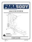
HOME GYM
PRODUCT ASSEMBLY
R~VI~ION C
358 EX350 ASSEMBLYPARTS LIST
SORT AND COUNTALL PARTSBEFOREBEGINNINGASSEMBLY
HARDWARE:
ITEM NAME/DESCRIPTION
7.
8.
q.
I0.
l&
17.
20.
27.
28.
29.
30.
32.
34.
30.
40.
,..
QTY
1/2X3 IN.HEX
HEAD
BOLT
............................................................................
: .................4
I.~ X 3 I/4 IN. HEXHEAD
BOLT
4.
1/2_X4 IN.HEX
HEAD
BOLT
...........................................................
: ....................:............. I
318 X ! i/2 IN. HEXHEAD
BOL
T"
1
3/8XI 3,’4IN.HEX
HEAD
BOLT
........................................................................................
3/8X2 IN.HEX
HEAD
BOLT
...............................................................................................
’
318 X 2 314IN. HEXHEADBOLT
2
3!8X3 IN.HEX
HEAD
BOLT
..............................................................................................
5116 X I IN. HEXHEADBOLT
¯ I~ IN. LOCKNUT
l
’
9
3!8IN"LOCKNUT
..............................................................................................................
14
5’16
iN"NUT
........................................................................................................................... 2
3;8IN"WASHER
.....................................................................................................................
I
5;16IN"WASHER
..................................................................................................................
4
3’’8IN"LOCK
WASHER
........................................................................................................
9
5/16IN"LOCK
WASHER
......................................................................................................
2
WEIGHT STACK CUSHION
~...........-’...................
, ................................2
l-l!4 IN. SQ.RUBBER
BUMPON
......................
I i~ IN. SQ.ENDCAP..... ; ....................................................................................................
2
I-3,’4 IN. SQ. ENDCAP
"
"
I
2 IN.SQ.
END
CAP
..............................................................................................................
16
CARRIAGE GUIDE
"
¯2
CABLE
RETAINING
"L"CLIP
............. ................................................................................
4
VINYL
SLEEVE
3 8 X73"8
...................................................................................................
2
"
I X 8 IN~GRIP
4
’ I-1/4 X 3 IN. GRIP
¯
2
1-114X 7 IN. GRIP
"
GUIDE
ROD
PIN
.....................................................................
; ........: ......................................
2
.;fiARAGLIDE
STRIP
...............................................................................................................
1
THUMBSCREW.
............................................
: ........................................................................
I
:..;:.................4
! ’2 IN.IDFLANGE
BEARING
........................................................................
3 ’4 IN. ID FLANGE
BEARING
6
SPACER
.................................................................................................................................. 1
STARLOCK
COLLAR
...:. ..... : ...............................................................................................
8
l
COTTER
PIN
..........................................................................................................................
"
KNOB
,
l
.~"8IN.
L-I~IN
.....................................
:.....................................................
WEIGHT
SELECT
PIN
..............................
.......................................................
l
"
1
PLUNGER
QUICK
LINK
..........................................................................................................................
.¢’!6X! 4 IN.SET
SCF,
EW.
..........................................
: ........, ...............................................
4
3 16IN. SNAP
LINK
..................
: ...........................................................................................
SPRING
................................................................................................................................... 1
"
2
3 4 IX;. II’) WASHER
358 EX350
ASSEMBLY
PARTS
LIST
SORT AND COUNT ALL PARTS BEFORE BEGINNING ASSEMBLY
WELDMENTS/PARTS:
ITEM. NA~IE/DESCRIPTION
QTY
2.
.~.
4.
5.
6.
7.
8.
9.
I0.
II.
12.
14.
15.
16,
17.
19.
20.
21.
22.
23.
24.
25.
27.
28.
20.
30.
32.
34.
35.
36.
37.
38.
3t).
40.
BEARING
HOUSING
WLDMT
...........................................
(6293701)
...............................
1
LOWROW
SWIVELBRACKET
WLDMT
.........................
(6199401)
...........................
:... 1
MAINUPRIGHTBOTTOM
SECTION¯WLDMT
................
(638.101)
...............................
1
LEFTPECDEC
ARM
WLDMT
...........................................
(6327101)
...............................
1
RIGHT
PECDECARM
WLDMT
........................................
(6327201)
...............................
1
PULLEY
BRACKET
SUPPORT
WLDMT
...........................
:
..........
(6293801)
....................
1
MAINUPRIGHT
TOPSECTION
.........................
(6-9.-01)
...............................
I
....
¯ ~.~WLDMT
"~
ADJUSTABLE
SEATSUPPORT
WLDMT
.........................
(6385601)
...............................
¯1
BACI~/SEAT
SUPPORT
WLDMT
.......................................
(6292701):
.............................
I
(6241601)
"
1
WEIGHT
STACKSUPPORT
BASEWLDMT
.....................
I
LAT
BAR
WLDblT
...............................................................
(6275301)
...............................
LEG
CURL
ARM
WLDMT
..................................................
(620220I)~..
...........................
I
"
PRESS ARM WLDMT..........................................................
(6.02801)
............................... 1
~....................................................... (6463301)
BACh’.
PAD
....................
...............................
2
(6.163401)
...............................
1
PRESS
SEAT
PAD
................................................................
1
PECDEC
SEAT
PAD
...................................................
S....... (6463501)
...............................
;
.................
CENTER
PULLEY
BRACKET
............................................
(6260301)
.............
1
u,.........j ...............(6281401)
CONNECTOR
PLATE
...............................
...............................
2
"
"~ ...............................
"
.~.:.......................(6.93101)
2
GUIDE ROD ................................................
(6375901])
...............................
WEIGHT
STACK
SPACER
..................................................
(6057.101)
...............................
1
WARRANTY
CARD
.............................................................
1
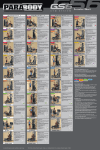
EXERCISE
WALL
CHART
..................................................
(6205601)
................................
WEIGHT
PLATE
BUSHING
................................................
(6382301)
.............. r ..............30
~..............(6251801)
1
PECDECLOOP
CABLE
.......................................
................................
I
PRIMARY
CABLE
................................................................
(6293201)
...............................
1
SECONDARY
CABLE
..........................................................
(6229201)
...............................
21LINK
CHAIN
...................................................................
(6075905}
................................
I
HEAD
WEIGHT
PLATE
.......................................................
(6223001)
...............................
1
(6189501)
...............................
WEIGHT
STACK
LABELS
..................................................
1.
, ............................(6202601)
..............................
PRESSARM
PIVOTBAR.......................
(3116201)
...............................
3-1.20.D. DIA. ’~,:’1 IN. BUSHING
PULLEY
....................
,. ......(3116101)
4-1/20.D. DIA. W:I IN. BUSHING
PULLEY
..............
.......................
4-1;20.D. DIA.x,x,72 IN. BUSHING
PULLEY
.....................
(3116102)
...............................
1
(6266001)
...............................
SELECT
CENTER
SHAFT
15 HOLE
...................................
I
; ...........; .......................... (6382401)
...............................
ANKLE
;’I’RICEP STRAP
.............
1
(6389701)
...............................
LOW
ROW
BAR
....................................................................
r .....................(6194601)
..............................
7 IN. ROLLER
PAD
........................................
(6176201)
...............................
12IN.ROLLER
PAD
............................................................
(61.3101)
...............................
ROLLER
PAD
SHAFT
..........................................................
1:5
(6.14~01)
.............................
WEIGHT
PLATES
.................................................................
3
358 EX350 ASSE.~B!
,Y INSTRUCTIONS
NOTE: BOLT LENGTH IS MEASURED FROM THE UNDERSIDE OF THE; HEAD OF THE BOLT.
" iii!!ii-il
BOLT LENGTH
BOLT LENGTH RULER:
.0
!," t
¯ I .... !.. 1
~
! ,I,,
l,
5
I , , ! I ,!
6
I.
358 EX350 A:~SEtvlBLY
INSTRUCTIONS
,THANK
YOU
.
:."
.;
" : ~2..-~.-_:.
. ."....~
~---~..
FOR PURCHASING THE ~ PLEASE SAVE THESE ASSEMBLY INSTRUCTIONs
FOR YOUR PERSONAL REFERENCE, AND ADDITIONAL SERVICE INFORMATION.,~,~"
. ¯
***IMPORTANT***
"::
THE EX350 MUST BE ASSEMBLEDON A FLair,
FUNCTION.
LEVEL SURFACE TO ASSURE ITS:’’"~
PARABODY INC. STRONGLY RECOMMENDSTHAT THIS PRODUCT BE ASsEMBI~ED.
PERSONS TO AVOID POSSIBLE INJURY.
KEEP ALL FRAME CONNECTIONS LOOSE, UNTIL INSTRUCTED IN THE ASSEMI
SEQUENCES TO SECURELY TIGHTEN.
""
¯
IF YOU EXPERIENCE ANY PROBLEMWITFL T,’HE ASSEMBLYOFTHIS PRODUC’-r,
CONTACT YOUR DEALER OR YOUR PARABODY CUSTOMER SERVICE
¯
TOOLS REQUIRED:RATCHET, 3/4 SOC ..K~or
WKENCH, 9/16 SOCKETor.WRt""
ADJUSTABLE WRENCH. $/32 ALLEN WRENCH, and RUBBER MALL~’T or HAMMER";
*** REFER TO ASSEMBLYDRAWING#1 FOR STEPS 1THRU 13 ***
Bolt HEADXVEIGHT
PLATEinto the threaded hole at top of SELECTCENTERSHAF’T, using one
(I } 3 ~ X I-1 2 IN. FlEX FlEADBOLT.one (l) 3.’8 IN. LOCKWASHER,
and one (l) 3.’8 IN. WASHER
(SEE DETAIL DL
Put seven t7} 2 IN. SO. END.CAPS into ends of tubes on WEIGHT
STACKSUPPORTBASE.
Attach one t I} 4-I 20.D. DIA. PULLEYwith 1 IN. BUSHINGto WEIGHTSTACKSUPPORTBASE
using one ( I } ~ $ X 2 IN. HEXHEAD
BOLT.one ( ! ) CABLE
RETAINING
"L" CLIP. a’.ad one (I) 3/8 IN.
LOCKNUT. (DO NOT TIGHTEN)
Insert
t~o {2~ I 2 IN. FLANGEBEARINGSinto
tube on LOWROWSWIVELBRACKET_.
Attach LOWROW SWIVEL BRACKETto YOKE on WEIGHT STACK SUPPORT BASE, using
one { 1 } ! 2 X 4 IN. I IEX HEAD
BOLT.and one (!) 1.’2 IN. LOCK
NUT.Tighten so it swivels freely, yet
doesn’t ~vo.bble.
~
LOOSELYattach’one
I I ~ .,t-l
" O.D’.’DII-X.
il
.
)
VEL
BRACKET.
usin~ one ~ I ~ 3 ,~ X 2 IN. HEXHEADBOLTand one t I ~ 3 8 IN. LOCKNU’[’.(DO NOT
TIGHTEN}
358 EX350 ASSE~.,IBLY INSTRUCTIONS
Attach BACK/SEAT SUPPORT ASSEMBLYto WEIGHT STACK SUPPORT BASE, u~ing one (1)
I/2 X 3-1 ’4 IN. HEX HEADBOLTand one (1) I/2 IN. LOCKNUT.(TIGHTEN ONLYUNTIL SNUG)
.Attach one (1) 4-1.’20.D. DIA. [~ULLEYwith’l IN. BUSHINGinto FRONT"U" PULLEYBRACKET
of the BACK/SEAT
SUPPORT,using one (1) 3/8 X 1-3/4 IN. HEXHEADBOLTand one (1) 3/8
LOCKNUT.
..
Attach one (I) 4-I;20.D. D1A. PULLEY,with 2 IN. BUSHING,between two fiats on MAINUPRIGHT
TOPSECTION.usln,...,
one (I) 3/$ X 3 IN. HEXHEADBOLTand one (I) ,~/g IN. LOCKNUT.
10.
Slide two (2) 7 3 "8 IN. VINYL SLEEVESover PRONGSof LAT BAR HOOKon MAINLrPRIGHT
TOP SECTION.
1 i.
Attach one (!) 3-1;20.D. DIA. PULLEYwith 1 IN. BUSHING.into PULLEYHOUSINGonMAIN
UPRIGHTTOP SECTION.usingone ([) 3/$ X 1-314IN. HEX HEAD BOLTand one (I) 318
LOCKNUT. (SEE DETAIL "B" ON DRAWING) (DO NOT TIGHTEN)
12.
Bolt MAIN UPRIGHT BOTTO~I SECTION to rear of WE~[GHTSTACKSUPPORTBASE, using
two (2) I;2 X 3 IN. HEX HEADBOLTSand two (2) 1/2 IN. LOCKNUTS.O’IGHTENONLYUNTIL
SNUG)
Bolt MAIN UPRIGHT TOP SECTION to BACKS,E, AT SUPPORT (FIRST INSERT TAB ON
BOTTOM
SE.CTION INTO THE END OF TOP SECTION.). using two (2) 1/2 X 3 IN. HEX HEAD
BOLTSand two (2) 1 2 IN. LOCKNUTS.
*** REFER TO ASSEMBLYDRAWING#4 FOR STEPS 14 AND 15 ***
14.
Insert
two {2) 2 IN. SO. ENDCAPSinto each end oftheBEARINGHOUSING.
SECURELY Assemble the BEARING HOUSING and PULLEY BRACKETSUPPORT to the MAIN
UPRIGHT.as shown on drawing, using two (2) 1/2 X 3-1/4 IN. HEXHEADBOLTSand ’~,vo (2) 1/2
LOCKNUTS. NOTE: MAKE SURE THE TOP AND BOTTOMUPR.IGHT FIT TOGETI--IER
BEFORE TIGHTENING.
*** REFERTO ASSEMBLYDRAWING#I FOR STEPS 16 THRU 26 ***
16.
Snap two (2) WEIGHTPLATEBUSHINGSinto.each
DETAIL A)
of the fifteen
17.
Place two (2) WEIGHTSTACKSPACERSover large
18.
Place t~o (2) 3 4 IN. WASHERS
over WEIGHTSTACKSPACERS.
19..
Place two (2) WEIGHT.STACK
CUSHIONSove~" 3/4 IN. WASHERS.
holes
(I5)
WEIGHTPLATES.
in WEIGHTSTACKSUPPI~RT BASE.
Insert each of the t~xo 12| GUIDERODSthrough the WEIGHT
STACKCUSHIONS
and into the
WEIGHT STACK SUPPORT BASE. (.NOTE: LUBRICATE GUIDE RODS WITH A SILICON OR
TEFLON SPRAY THAT IS AVAILABLE AT tMOST HARDWARESTORES.}
358 EX350 ASSEMBLY INSTRUCTIONS
USING,EXTREME
CARE. slide each of the fifteen (15) WEIGHTPLATESdown ow.’r the GUIDE
RODS onto the WEIGHT STACK CUSHIONS. (PIN HOLE FACING OUT)
22.
Slide HEADWEIGHTPLATE ASSEMBLYdown over
STACK.
the GUIDE RODS onto the
WEIGHT
Position
the GUJDE RODS under the GUIDE ROD BRACKETofthe MAIN UPRIGHT TOP
SECTION,and hold in place using two (2) GUIDERODPINS. (SEE DETAIL
24.
Apply the WEIGHTSTACKLABELS to the WEIGHTPLATES¯ (SEE DETAIL A)
25.
Insert
26.
Peel backing from one ( I I !-!:4 IN. SO. RUBBER
BUIvlPON
and securely attach to the 1 1/2_ IN. END
CAP on PRESS ARMSTOP.
one (I) 1-I,_
IN. ENDCAP12 GAinto PRESS ARMSTOP.
*** REFER TO ASSEMBLYDRAWING#2 FOR STEPS 27 THRU 40 **~’
27.
Attach two (2) 4-1 ’20.D. DIA. PULLEYS
with 2 IN. BUSHING.to PRESSARMusin2~ two (2) 3/8
IN. HEXHEADBOLTSand two (2) 3/g IN. LOCKNUTS.
Insert two (2) 3 ’4 IN. FLANGEBEARINGSinto
SECTION.
’,
~nds of ROUND
TUBEon blAIN UPRIGHTTOP
29.
To attach PRESS ARMto MAINUPRIGHTTOP SECTION.raise PRESS ARMto align collars with
ROUNDTUBE on MAIN UPRIGHT TOP SECTION and insert
PIVOT BAR. ALIGN two (2) 5/16
I/4 IN. SET SCREWS
into holes on collars of PRESS ARMANDTIGHTEN.(USE OF
LUBRICANT MAY HELP. SLIDE PIVOT BAR)
30.
Slide t~vo (2) i-! "4 X 7 IN. GRIPS on the HORIZONTAL
HANDLES
of the PRESS&RM,and two t2)
I-I :4 X 5 IN. GRIPS on the VERTICALHANDLES.(NOTE: IF" A LUBRICANT
IS REQUIRED,
PARABODY RECOMMENDS THOROUGHLY COATING THE INSIDE OF THE GRIP WITH
RUBBING ALCOHOL)
l.nsert
one ( ! ) 2 IN. SO. ENDCAPinto top end of the LEGCURL/ARM
ASSi~MBLY,,
Insert one ( I )’2 IN. SO. ENDCAPinto top end of LEGCURLEXTENSION
NECK.of the
BACK/SEAT SUPPORT.
Insert two (2) I 2 IN. FLANGEBEARINGSinto the BUSHINGin the LEG CURLEXTENSION
NECK of the BACK/SEAT SUPPORT.
34.
Assemble the LEG CURL ARMASSEMBLYto the LEG CURL EXTENSIOS NECKof the
BACK/SEAT
SUPPORT.using one (l) I:~ X .3 1/4 IN. HEXHEADBOLTand one (l) !/2
LOCKNUT. (NOTE: TIGHTEN UNTIL SNUG BUT STILL ABLE TO SWIVEL)
Peel awa.x paper baekin’2-’ on one (.1). !-1:’4 IN. SQ. RUBI~.ER
BUMP.ON..attach
to LEGCURL
EXTENSION NECK of the BACK~SEAT SUPPORT where LEG CURL ARM ASSEMBLYmeets.
7
358 EX350
ASSEMBLY INSTRUCTIONS
LOOSELYassemble one (1) 3 I/20.D. DIA. PULLEYwith I IN. BUSHINGinto PULLEYBRACKET
on the LEGCURLARMASSEMBLY.
..... Using one (1) 3/8 X 2 IN. HEXHEADBOLTand one (1)
IN. LOCKNUT.
37.
Attach two (2) ROLLERPADS to the LEG CURLARMASSEMBLY.using one (I) ROLLER
SHAFT. and two (2; STAR LOCK COLLARS. (NOTE: WHENUSING THE LOWPULLEY OFF
THE LEG CURL ARM ASSEMBLY, LOCK IN PLACE BY INSERTING L-PIN INTO BUSHING
ON THE LEG CURL EXTENSION NECK)
38.
Assemble two (2} ROLLERPADS to the BACKSEAT SUPPORT. using
SHAFT. and two (2) STAR LOCKCOLLARS.
39.
A~tach one (i) 3-1 20.D. DIA. PULLEYwith I IN. BUSHINGinto REAR"U" PULLEYBRACKET
of BACK/SEAT
SUPPORT.using one (I) 3/8 X I-3/4 IN. HEXHEADBOLTand one (1) 3/8
LOCKNUT.
~
.40
Attach BACKPADto BACK/SEATSUPPORT,using two (2) 3,’8 X 3 IN. HEXHEADBOLTSand two
(2) .3.’8
IN. LOCK WASHERS. (NOTE: HIDEM WELTCLIP SHOULDBE LOCATED
BOTTOM)
one (1)’ROLLER
*** REFER TO ASSEMBLYDRAWINGo#3 FOR STEPS 41 THRU 44 ***
Attach two (2) .~-i O.DI DI A. PULLEYS with 1 IN."BUSHING tothe CONN
ECTOR PLAT
ES, usin g
two (2) .3 ’8 X 2 IN. HEXHE~A.DBOLTSand two (2) 3/8 IN. LOCKNUTS
(DO NOTTIGHTEN)
41.
¯ 42.
Slide four (4) I X 8 in. GRIPSover each, end of the LATBAR. and LOWROWBAR." (NOTE:IF
LUBRICANT IS REQUIRED. PARABODY RECOMMENDS THOROUGHLY COATING THE
INSIDE OF THE GRIP WITH RUBBING ALCOHOL)
NOTE: BEFORE PROCEEDING WITH CABLE INSTALLATION,
AS MUCHSPIRALING AS POSSIBLE.
UNRAVEL CABLE, A~N’D REMOVE
To install
the PRIMARYCABLEinsert end of CABLEwith THREADED
FITTING into
GROOVEof PULLEY Upwards between PULLEY and LAT BAR HOLDERon MA][N UPRIGHT
TOP SECTION. (REMOVE PULLEY FOR EASE OF INSTALLATION)
¯
Pull
¯
Run CABLEdo~,.n
SUPPORT.
CABLEdown until
CLEVIS CONNECTOR
stops
a.galnst
PULLEYand LAT BAR HOLDER.
and under TOP PULLEYon PRESS ARM. then over PULLEYon BACK/SEAT.
Pull CABLEarotmJ PULLEYon BACK/~EATSUPPORTand towards the PRESS ARM. Run
CABLEover BOTTOM
PULLEYof PRESS ARMand back. through the opening of the BACK¯
SEAT SUPPORT. to the SMALLPULLEY.
Wliil¢ pulIi~g.CABLE down o~er SMALLPULLEYon the~back of the BACK/SEATSUPPORT.
insert
the CABLEEND arotmd one of the PULLEYSor" the PULLEY/PLATECONNECTOR
........
ASSEMBLY.
358 EX350 ASSEMBLY INSTRUCTIONS
PuII.CABLE up to the PULLEYin the PULLEYHOUSINGabove the WEIGHTSTACKon the
MAIN UPRIGHTTOP SECTION. Pull CABLEover and down PULLEYand thru hole in MAIN
UPRIGHT TOP SECTION to SELECT CENTER SHAFT on HEAD WEIGHT PLATE.
(REMOVE PULLEY FOR EASE OF INSTALLATION)
Attach the PRIMARYCABLEto the HEADWEIGHTPLATE ASSEMBLY.b.v threading
STUD into .the SELECT CENTER SHAFT and TIGHTEN COMPLETELY.
44.
the
¯
To install the SECONDARY
CABLE.start by inserting the end of’the CABLE
into the front of the
LOW ROW SWIVEL BRACKET. (REMOVE.PULLEY FOR EASE OF INSTALLATION)
¯
Pull the CABLEupward behind the PULLEY
until the WHITEBALLstops at the frdnt of the LOW
ROW SWD,’EL BRACKET.
Run CABLEaround the BOTTOMPULLEY of:the
CONNECTOR ASSEMBLY.
(SUSPENDED) PULLEY/PLATE
Pull CABLEunder PULLEYon WEIGHTSTACKSUPPORTBASE tow’ards fro~t of bIACHINE.
(NOTE: BE SURE TO PLACE CABLE RETAINING "L" CLIP UNDER PULLEY
AFTERWARDS)
To finish
SECONDARY
CABLE INSTALLATION. run CABLE under PULLEY on the PULLEY
BRACKETof the LEG CURL EXTENSION,~Rbl. (REMOVE PULLEY FOR I.’ASE OF
INSTALLATION)
*** REFERTO ASSEMBLYDRAWING#4 FOR STEPS "45 THRU58 ***
LOOSELYassemble two 12) 4-I ~ DIA. PULLEYSwithI IN. BUSHING.to the PULLEYBILA, CKET
SUPPORTas shown, using two (2I 3 8 X 2 IN. HEXHEADBOLTS. t~vo (2) CABLERETAINING
CLIPS and two ~2~ 3 8 IN. LOCKNUTS.(NOTE: DO NOT TIGHTEN)
Insert four (4) "~ 4 IN. FLANGE
BEARINGS
into the TOPand BOTTOM
ends of the BI[JSHINGSin the
BEARING HOUSING.
47.
lnsert’fbur
{4) 2 IN. SQ. ENDCAPSinto open ends of’LEFT and RIGHTPEC DECARMS.
48.
Insert PIVOT of each ARMinto FLANGEBEARINGSin the BEARINGHOUSINGa~ad secure with
two {2~ STAR LOCK COLLARS.
49.
Peel offbacking
fi-om t~o (2} 1 IN. SQ. PLASTICSTOPS. attach
to ANGLEIRON’STOPBRACKET
on. BEARINGHOUSINGwhere ARMCAMSmake contact.
50.
Slide LARGEFOAMROLLERPADS onto LEFT and RIGHT PEC DEC ARblS. (NOTE’." IF
LUBRICANT IS REQUIRED, PARABODY RECOMMENDS THOROUGHLY COATING THE
INSIDE OF THE GRIP WITH RUBBING .ALCOHOL)
52.
SECURELVassemble
the SEAT PAD to MAIN UPRIGHTBOTTOMSECTION usilag
two (2) 3/8
2-3 4 IN. HEX HEADBOLTSand two t2) 3/8 IN. LOCKWASHERS.
9
358 EX350 ASSEMBLY INSTRUCTIONS
53.
SECURELY
assemble the BACKPADto MAINUPRIGHTusing two (2) 3/8 X 3 IN. FlEX HEAD
BOLTS and two (2) 3:8 IN. LOCK WASHERS.(HIDEM WELTCLIP SHOULDBE FACING
DOWN)
54.
¯
To assemble the PEC DECLOOPCABLE,start by LOOSELY
attaching each end of the CABLEto
CAMSof the LEFT and RIGHT PEC DEC ARMS,using two (2) 5116 X I IN. HEXHEAD
BOLTS.four(4) 5 "16 IN. WASHERS.
two (2) 5/16 IN. LOCKWASHERS.
and two I’.2) 5/16
NUTS. (SEE DETAIL C)
¯
Rut1 CABLEback to the PULLEYSon the PULLEYBRACKETSUPPORT. Drape the CABLE
over the PULLEYS
o,a both sides. Position the CABLERETAINING
CLIPS over the top of the
CABLE
at a -15 degree angle. This will create a LOOPin the center of the hanging CABLE.(SEE
DETAIL A)
¯
LOOSELYassemble one (I) 4-I/2 DIA PULLEYwith I IN. BUSHINGto the CENTERPULLEY
BRACKET
a~ shown ~n (DETAILD). using one (I) 3!8 X 2 IN. HEXHEADBOL’I;
CABLERETAINING"L" CLIP, and one (I) .~/8 IN. LOCKNUT.
¯
Assemble the CENTERPULLEYBRACKETASSEMBLY
over the LOOP CABLEas Sh.o~vn on
drawing. Position the CABLERETAININGCLIP under the CABLE.(SEE DETAILA)
Tiahten all
LOOSEPULLEYand CABLEconnecttons.
Attach the end ofone { i ~ 21 LINKCHAINto the CENTERPULLEY
BRACKET
using one (1) 5/16 IN.
SNAP LINK. (SEE DETAIL B)
Attach the other end of the CHAINto the end of the CABLEin the LOWROWSWIVELBRACKET
on
"the MAIN.UNIT using one (I) QUICKLINK.
TIGHTEN ALL BOLT CONNECTIONS AT THIS ThME. (NOTE: IF PRESS ARM APPEARS TO
BE OFF CENTER.ALIGN PULLEYS WITH STOP ON .BACK SEAT SUPPORT BEFORE AND
DURING TIGHTENING)
*** REFER TO ASSEMBLYDRAWING#3 FOR STEPS 59 THRU 67 ***
60.
¯
Attach LAT BARto PRIMARY
CABLEwith one (1) 5:16 IN. SNAP LINK (SEE DETAIL
¯
Attach one I I ) "; 16 IN. SNAPLINKtoeach end of the second 21 LINKCHAIN
to l~e used with
eitherthe
LOWROWPULLEY on the LEG CURL ARMASSEMBLYor the UPPER PULLEY.
¯
NOTE: SEE TH E EXERCISE WALL CHART FOR INEORMATION ON THE VARIOUS
ACCESSORi ES THAT ATTACHTO THE 5/16 IN. SNAP LINKS.
AttaCh eight (8~ PARAGLIDE
STP, IPS to the SEAT SUPPORTTUBEon the BACKSEATSUPPORT.
as sho~ n in (DETA
I L H) using the tbllowing steps:
,
Tlaoroughl.~ cle;m all inside surfaces ~here the PARA~LID~strip~ are to be attached.
Remoxe the paper backin’.2-’ from the PARAGLIDE
stt~ips and firmly apply the mto all shownsurfaces
( 8 places~.
10
358 EX350
ASSEMBLY INSTRUCTIONS
61.
Assembl~ one ( I ) SPRINGPIN ASSEMBLY
to the SPRINGPIN ASSEMIIILY
HOUSING
located
the SEATSUPPORT
TUBEusing one (l) KNOB,one (l) PLUNGER.
one (1) SPRING,one
SPACER.and one (l) COTTER
PIN. (SEE DETAIL
62.
Insert one ( I ) I i 2 IN. SO. ENDCAP12 GAinto end ofthe SPRINGPIN ASSEMBLY
HOUSING
fl~e SEAT SUPPORTTUBE. (SEE DETAILH)
63.
Insert
one( I ) 2 IN.SQ.ENIDCAPintofrontendof theADJI]STABLE
SEATSUPPORT.
64.
Assemble t~vo (2~ ROLLER
PADSto the ADJUSTABLE
SEATSUPPORT,using one (1) ROLLER
PADSHAFT. and two {2} STARLOCKCOLLARS.(SEEDETAILJ)
65.
Attach the SEATPADto the ADJUSTABLE
SEATSUPPORT.using two (2) 3/8 X 3 IN. HEXHEAD
BOLTSand two t2~ 3 8 IN. LOCKWASHERS.
66.
Placethe .~DJUSTABLE
SEATSUPPORTASSEblBLY
intothe SEATSUPPORTTUBE l~catecl
on
the BACKSEAT SUPPORTby disengaging
the SPRINGPIN ASSEMBLY.
67.
Install
one ( I ) THUMBSCREW
into the SEATSUPPORT
TUBE.(SEE DETAILH)
vtv WARNING
v w~
MAKESURE SNAP LINKS ARE FASTENED BEFORE DOING EXERCISES.
! !! WARNING
! !I
DO NOT OPERATE THIS MACHINE WITH LAT BAR OFF SAFETY HOOKS
EXCEPT DURING HIGH PULLEY EXERCISES. ALSO, LAT BAR !S NOT
TO BE USED FOR PULL-UPS. .
PLEASE NOTE:
IFUPON ASSEMBLY, THE HEAD PLATE DOES NOT SIT ON :FOP OF
THE FIRST PLATE, PLEASE PUSH HEAD PLATE DOWN, INSERT THE
WEIGHTPIN TO A DESIRED RESISTANCE AND DO A FEW REPS ON
ONE OF THE STATIONS. THIS WILL SEAT THE CABLE SYSTEM.AND
ALLEVIATE THE HEAD PLATE FROMSITTING UP.
PLEASE NOTE:
"~"
WE RECOMMEND
CLEANING YOUR PRODUCT (PADS AND FI~kME) ON.
- REGULAR BASIS, USING WARMSOAPY WAT.ER. ALSO, TOUCH-UP
PAINT CAN BE PURCHASED FROM YOUR PARABODY DEALER, OR FROM
..
YOUR
PARABODVCUSTO~tER
SERVICE
REP~SV.r~’rA¢IXq~
1-800-328-97i4
11
....SEE bETAIL’F"
1"7_PLC.5.")
¯
°SEEDETA~L’F
PULLEY
tSF1,At.KET
.--tPF.r. IDErAF, MLEF’r
PEr..D’EC"
P,ACK
DRAWING
ParaBody,Inc.
DE.TA IL "C."
~{~
RAMSEY.MINNESOTA
HQ~3Kr
,.
~/a"NU’f’
’’ PULLI"’i’
H~lt
W/I" BU~H~rNG
’.BOLT
¯ /g SPLITL.~,K
¯ WA.SHEP,
¯ o o
oo
ROLLER PAD
SHAFT