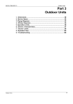
1
MCAC-DTSM-2006-01
Dimensions
2. Dimensions
MDV-D252W/CSN1 MDV-D280W/CSN1 MDV-D335W/CSN1
MDV-D450W/CSN1
751
1372
823
1290
793
1586
MDV-D400W/CSN1
5
5
545
1095
3. Service Space
3.1 Power supply equipment is preferred to be installed by the side of the outdoor unit;
3.2 Ensure there is sufficient space for the maintenance of the outdoor unit;
3.3 Proper space between outdoor units should be kept;
Outdoor Units
127
Service Space
MCAC-DTSM-2006-01
3.4 Distance between foot screws is shown as follows;
(unit: mm)
MDV-D252W/CSN1 MDV-D280W/CSN1 MDV-D335W/CSN1
980
MDV-D400W/CSN1
735
798
598
MDV-D450W/CSN1
3.5 Outdoor unit arrangement
Outdoor units are higher than the surrounding buildings
128
Outdoor Units
MCAC-DTSM-2006-01
Service Space
Outdoor units are aligned in one line
Outdoor units are aligned in two lines
More than 2 lines of outdoor units
3.6 Outdoor units are lower than the surrounding obstacles
If the outdoor units are lower than the surrounding obstacles, in order to ensure an effective “heat
exchange “a conduit is strongly recommended to help the heat emission and avoid the discharging air
Outdoor Units
129
Piping Diagram
MCAC-DTSM-2006-01
being absorbed into the system again. The conduit is made on the installation spot with the height
HD=H-h.(Note:Because the outdoor fan motor have no enough static pressure, the Max. Length should
be less than 3meters.)
3.7 When there are obstacles above the outdoor unit:
The top of any pile around the outdoor unit should be at least 800mm below the unit top, unless there is
mechanism for air discharging.
4. Piping Diagrams
4.1 Refrigerant System Diagram
There’s no constant speed compressor “F2” in the 8、10、12HP system.
4.2 Function of key parts
ST1: when the operating mode of A/C system changes, turn the flow direction of the refrigerant;
ST2: change the heat exchanger area according to the load in cooling mode;
EXV: adjust the refrigerant flux;
SV1: when there’re more than one module in the combination, SV1 is used to cut off the refrigerant flow
among modular. If the module is in standby mode, Sv1 will be closed and refrigerant can’t enter the module;
SV2: cooling down the compressor when the discharge gas temperature of any compressor is more than
100C ;
130
Outdoor Units
MCAC-DTSM-2006-01
Piping Diagram
SV3: adjust heat-exchanger area of outdoor when in heating mode;
SV5: used when starting heating mode or defrosting mode;
SV6: adjust the refrigerant flux in cooling mode. And in heating mode it will be always open.
4.3 How to check the valves:
a) Electronic Expansion Valve (EXV): when the outdoor unit is power on , the two EXVs firstly close with
700p,then they open with 350p and enter standby mode, two EXVs’ action is not at the same time.
b) Electromagnetic Valve:
when the outdoor unit is power on, the SV1 open immediately, so you can check the valve as soon as the
outdoor unit is power on;
when the compressor starts working in heating mode, the SV3 is open immediately, so you can check the
valve as soon as the compressor start; 5 minutes after the outdoor unit start heating mode,SV5 will open;
when the compressor starts working in cooling mode, the SV6 open immediately, so you can check the valve
as soon as the compressor starts; control the discharge temperature by adjusting the resistance of the
temperature sensor, when the discharge temperature is higher than 105℃ ,SV2 open immediately.
c) Four way valve: when starting heating mode , main four-way valve ST1 turn direction after the
compressor has worked for 55s; when the capacity demanded by the indoor unit is less than 12 ,the
auxiliary four-way valve ST2 turn direction.
SV6
SV1
Liquid side
EXV
ST2
SV3
EXV
SV5
Gas side
ST1
SV2
Gas balance
D
F1
F2
Gas balance
Outdoor Units
131
Wiring Diagrams
MCAC-DTSM-2006-01
5. Wiring Diagrams
MDV-D252W/CSN1
132
MDV-D280W/CSN1 MDV-D335W/CSN1
Outdoor Units
MCAC-DTSM-2006-01
MDV-D400W/CSN1
Outdoor Units
Wiring Diagrams
MDV-D450W/CSN1
133
Functional parts and safety devices
MCAC-DTSM-2006-01
6. Functional parts and safety devices
Part
Model
MDV-D252, 280W/CSN1
Digital Scroll
Compressor
MDV-D335W/CSN1
ZPD72KCE-TFD-433
Constant Scroll
ZP57K3E-TFD-422
ZP67KCE-TFD-420
Opening temperature
110±5℃/ 145±5℃
110±5℃ / 145±5℃
Trip current
64A (2~10s) /47 A (2~10s)
64A (2~10s) / 55A ( 2~10s)
Crank case heater
70W×2
Outdoor fan motor
YDK400-8-YA
Safety thermostat of
On
145±5℃
fan motor
Off
95±15℃
Security
Devices
High pressure switch
OFF:44kg/cm 2 / ON:32kg/cm 2
Low pressure switch
OFF:0.5kg/cm 2 / ON:1.5kg/cm 2
Temperature sensor (condenser outlet)
25℃=10KΩ
Temperature
Thermostat (Digital discharge)
sensor
When Tmax≥118℃ all the compressors are off
Thermostat (Fixed discharge)
Part
Model
MDV-D400,450W/CSN1
Digital Scroll / Constant Scroll
ZPD72KCE-TFD-433
/
ZP67KCE-TFD-420 (X2)
Opening temperature
110±5℃ / 145±5℃
Trip current
64A (2~10s) / 55A ( 2~10s)
Crank case heater
70X3 W
Outdoor fan motor
YKD450-6A ×2
Compressor
Safety thermostat of
On
145±5℃
fan motor
Off
95±15℃
Security
Devices
High pressure switch
OFF:44kg/cm 2 / ON:32kg/cm 2
Low pressure switch
OFF:0.5kg/cm 2 / ON:1.5kg/cm 2
Temperature sensor (condenser outlet)
25℃=10KΩ
Temperature
Thermostat (Digital discharge)
sensor
When Tmax≥118℃ all the compressors are off
Thermostat (Fixed discharge)
134
Outdoor Units