1
A LOOK INTO THE CIRCUITRY OF THE TEAC A3440
The supply is also tasked with the job of powering up the Brake and Capstan
solenoids but done in a rather mysterious way for the unwary. It must be remembered
that the two sets of solenoids work in opposite ways, the capstan solenoid has to be
energised to engage the pinch roller but the brake solenoids have to be energised to
disengage the brakes. Note that the Left and Right hand brake solenoids are wired in
series and both energise at the same time. Now the mysterious bit!
First however, a reminder that a solenoid requires more power to engage it than that
required to keep it engaged and so there are two supply paths made available for the
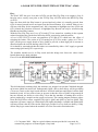
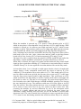
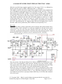
solenoids. A simplified brake solenoid circuit appears on Page 24.
Fuse 902 (2.5 Amp anti-surge) provides one of the supply paths; fed via D614 it is
un-switched, available all the time and is used as the holding supply. For the full
power engage voltage, this honour is given to Q606, driven by Q607, which gets a
pulse from Q722 via C714 on the control board when required. This pulse engages the
pinch wheel and takes off the brakes, after which the current from D614 is sufficient
to maintain the solenoids in their held positions. As we shall see later, this is not the
end of the Brake/Capstan story as elements exist on the control board for switching
the return current paths of the solenoids.
Fuse 905, Fuse 906 and Fuse 907 (All 1 Amp anti-surge) provide protection for the
reel motors and I must confess that reverse engineering of this circuit was a real pain.
Some of the description that follows is still based on a little guesswork but if anyone
can come up with a better description, please correct me!
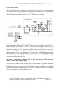
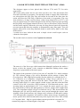
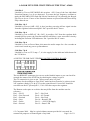
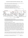
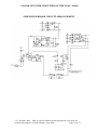
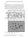
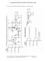
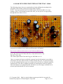
For example, the motor circuit makes use of a diode switch, consider the following.
With the centre line open circuit, the AC voltage of whatever polarity cannot pass
through from input to output as it always meets a reverse biased diode. If however the
open circuit centre line is replaced with a short circuit then the AC input can reach the
output. A positive cycle will pass through D617, the short circuit and then through
D616. A negative cycle will pass through D618, the short circuit and then through
D615. By substituting an active switch in place of the centre line then the AC voltage
can be switched to the motor. This circuit operation is not readily apparent looking at
the Teac circuit but if you re-draw then the true story becomes revealed.
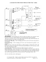
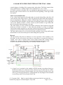
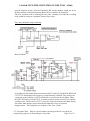
I have redrawn the circuit, removing the Large/Small Spool switches to make things a
little clearer.
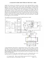
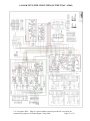
First the Large Spool circuit as depicted in the Teac circuit.
I shall place the circuit on the next page so that the description is closer to it.
© L.Carpenter 2009 May be copied without consent provided it is not used for
commercial purposes or financial gain of any kind.
Page 4 of 31