1
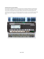
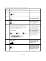
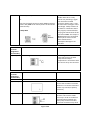
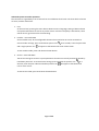
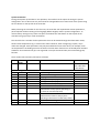
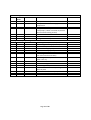
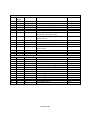
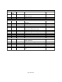
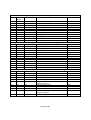
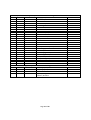
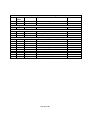
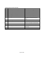
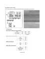
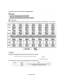
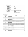
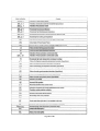
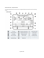
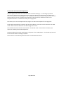
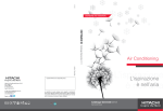
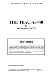
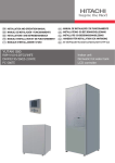
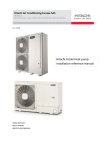
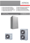
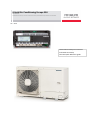
Hitachi Air Conditioning Europe SAS
UK Branch.
Whitebrook Park, Lower Cookham Road, Maidenhead, Berkshire SL6 8YA
V1 – 2/15
Hitachi Advanced System Controller
and Yutaki Heat Pump
Technical Quick Reference guide
General
This manual is provided by Hitachi Air Conditioning Europe (HACE) for reference use by qualified
installers of the Yutaki range of heat pumps. Qualified installers will have attended the Hitachi
recognised training course before installing any Hitachi product. Non-attendance of such a course in a
recognised Hitachi training centre may void the warranty on any products supplied.
This manual does not replace the service manual which is referred to within these pages. This manual
provides guidance only as to the key information about the Advanced System Controller (ASC) and
Yutaki heat pump settings and error messages.
This manual refers to the Yutaki M series heat pump service manual SMGB0090 rev.0 – 01/2014
No part of this publication may be reproduced, copied, filed or transmitted in any shape or form without
the express permission of HACE.
All regulations for water usage, energy efficiency, electrical safety and others as applicable to the
installation in force at the time of the installation must be adhered to and all such regulations shall take
precedence over any advice and inference given herein.
Page 2 of 24
Contents
Page
Advanced System Controller Hardware ............................................................. 4
Advanced System Controller Connections ......................................................... 5
Advanced System Controller engineering access .............................................. 9
Advanced System Controller Parameter and menu list
................................... 10
Advanced System Controller heat Pump information display .......................... 15
Advanced System Controller fault codes
.....................................................
17
............................................................
18
Yutaki Heat Pump display indications and error codes ....................................
20
Room Control Unit - Set Up Instructions
22
Yutaki heat Pump DIP switch settings
...............................................
Page 3 of 24
Advanced System Controller hardware.
The controller is supplied with 2 sets of connectors which are uniquely numbered to avoid confusion
when making connections. The unit is also supplied with clip on guides for routing cables and safety
covers which can be clipped into place after installation. Space must be left above and below the
controller for the safety covers to be fitted (if required). The controller can be mounted using the fixing
holes at each corner or clipped onto a standard DIN rail. The controller and connectors are shown
below.
Page 4 of 24
The controller connection functions are outlined in the table below:
Power
Connection
Terminals
Note: Total maximum connected load = 10 Amps
Live, Neutral and Earth from 13A switched fused outlet
230v ~
adjacent to controller
X1
Live, Neutral and Earth to Heating circulation pump
Function
Mains power to controller
Heating water circulation HC1
X2:X3
Live x 2, Neutral and Earth to heating circuit 1 mixing
valve
Optional control function where
the primary heating circuit water
temperature may be set below
the stored buffer temperature
X4
Live, Neutral and Earth to heating circuit 2 circulation
pump
X5:X6
Live x 2, Neutral and Earth to heating circuit 2 mixing
valve, external boiler mixing/bypass valve, external
boiler pump (X5 only) or control relay of electric
heater(s) in the heating circuit. NOT to be used to
power the electric heaters directly.
Optional control function where
a secondary heating circuit is
controlled independently from
the main heating circuit
Optional function depending on
system configuration. May be
used to control the temperature
of a secondary heating circuit,
control the temperature of
water from an external boiler or
provide an enabling signal to an
electric heater. Note: This
output is NOT designed to be
connected directly to an electric
heater which would result in
catastrophic damage to the
controller
Note: 3Amps Max
X7
Live, Neutral and Earth to Domestic hot water loading
pump or valve
Controls the diversion of water
from the heat pump to the
Domestic hot water cylinder
main heating coil
X8
Volt free (isolated) contact to Heat Pump
Heat pump enable. Note this is a
relay contact only switching a
mains voltage signal from the
heat pump. Safety isolation of
the heat pump is essential
before carrying out maintenance
of this connection.
Page 5 of 24
X9
Volt free (isolated) contact to boiler
Or
Volt free (isolated) contact to switch DHW immersion
heater relay. NOT to be used to power the Immersion
heater directly.
3 Amps Max
Control
Terminal
Designation
(and number)
A1 (1 & 2)
Optional function of boiler
enable. Note this is a relay
contact only switching a signal
from the boiler or DHW
immersion heater relay. It may
be either mains voltage or extra
low voltage. Safety isolation of
the boiler or immersion heater
relay supply is essential before
carrying out maintenance of this
connection. Note: This output is
NOT designed to be connected
directly to an electric heater
which would result in
catastrophic damage to the
controller
Connection
Function
0 – 20mA signal to Heat Pump
Control signal sourced from heat
Pump which varies the Heat
Pump desired output
temperature in accordance with
the current set by the controller
Communication Connection
Terminal
Designation
(and number)
C1
Not available on this controller
C2 (29 & 30)
RF Receiver
Function
C3 (27 & 28)
Heat Pump communication
channel. This must be made
correctly in order to enable full
communication between the
heat pump and the controller.
Incorrect connection may cause
RS485 to Heat Pump (Polarity sensitive)
Page 6 of 24
No function
Communication from the room
unit to the controller via the RF
Receiver. This can be connected
either way round (not polarity
sensitive)
C4 (26)
Do not connect
Not available on this controller
damage and/or prevent correct
operation of the Heat Pump.
No function
Switch
input
Terminal
Designation
(and number)
B1 (23 & 24)
Connection
Function
Tariff / Timer input from volt free contact
Optional function to inhibit hot
water loading. Can otherwise be
used to disable heat pump for
load shedding applications
Domestic Hot Water boost input from volt free
momentary contact
Optional function to provide a
boost to hot water production
outside of normal loading times.
This is a one-time operation and
heats the DHW cylinder until the
target temperature is reached
and then reverts to normal
heating mode
Terminal 23 is
common with
function B2
B2 (22 & 23)
Terminal 23 is
common with
function B1
Page 7 of 24
Temperature
Sensor
Terminal
Designation
(and number)
U1 (6 & 7)
Connection
Function
U2 (8 & 9)
HC1 flow temperature
U3
Not available on this controller
U4 (10 & 11)
HC2 flow temperature
U5 (12 & 13)
Domestic Hot water temperature
U6 (14 & 15)
Boiler flow temperature
U7
U8 (16 & 17)
Not available on this controller
Outside sensor
Note: Temperature sensor inputs are not polarity
sensitive and can be connected either way round
System flow temperature
Page 8 of 24
Measures the temperature of
heating system water in the
buffer
Primary heating circuit flow
temperature, positioned after
HC1 mixing valve
No function
Secondary heating circuit flow
temperature, positioned after
HC2 mixing valve
Measures the temperature of
water in the DHW cylinder.
Note: it is essential that this
sensor makes good thermal
contact with the cylinder and is
mechanically sound. Improper
fitting may render space heating
function inoperative due to
perceived hot water demand
Detects the temperature of
boiler source water
No function
Optional sensor which may be
used to augment the heat pump
sensor for detecting outside
temperature. Must be placed
out of direct sunlight and
preferably on a North facing
wall.
Advanced System Controller operation
The controller is organised by a set of menus that are available at three levels. The three levels of access
are User, Installer and Service.
1. User
At the user level, pressing the menu button allows access to language, setting of date and time
and system information as well as any active alarms. Until the heat pump is switched on, there
will be alarms, ignore these for the time being.
2. Installer – Pass-code 3636
At the installer level, all the configurable elements that need to be set can be accessed. To
access Installer settings, press and hold the spanner icon
and a single spanner icon
for 5 seconds, enter the pass-code
will appear at the bottom left corner of the screen.
To exit Installer mode, press and release the ESC button.
3. Service – Pass-code 6565
The Service level gives access to system parameters that do not normally need to be altered by
installation personnel. To access Service settings, press and hold the spanner icon
seconds, enter the pass-code and a double spanner icon
corner of the screen.
To exit Service mode, press and release the ESC button.
Page 9 of 24
for 5
will appear at the bottom left
System Parameters
During initial power up and after a rest operation, the installer has the option of setting the system
configuration. This is done once only and cannot be changed without a manual reset of the system using
the rest button on the top left of the controller.
When powering the controller for the first time, the controller will respond with a Reset option RST 1,
(Press OK) and will allow setting of the language (default English) and the system Configuration. To
restore factory settings at any other time press and release the reset button on the top left of the
controller using a pen tip or small screwdriver.
The controller has a number of other parameters that can be viewed through the information menus;
these include temperatures (T), K values and C values. However, when configuring a system, only P
values are changed. Some parameters may only be enabled for access after others, for example, it will
not be possible to set loading times for hot water if the hot water function has not already been enabled
elsewhere. The Parameter list (P) is not organised in a simple numerical order, but accessed by group
function.
There are 8 menus and many sub menus as follows
Menu SubSub-sub-menu Function
menu
00
n/a
n/a
Current active alarms
General configuration
01
1-4
n/a
02
n/a
n/a
03
00
n/a
03
01
n/a
03
02
n/a
03
03
n/a
03
04
n/a
03
05
n/a
03
06
n/a
03
03
07
08
n/a
n/a
DHW loading times
Date and time setting
Language
Heating circuit 1 (HC1) type
Heating circuit 2 (HC2) type
Domestic Hot Water (DHW) type
DHW electric heater
Boiler manual release after HP fault
(allows boiler to keep system operating in
the event of a Heat Pump fault)
Electric heater manual release after HP fault
(allows electric heater to keep system
operating in the event of a Heat Pump fault)
Summer / Winter changeover enable
12 / 24 Hour clock display selection
Page 10 of 24
Parameters
See Controller
fault codes later
in this section
P101
P201
P301
P310
P008
P009
P010
P011
System settings
Menu Submenu
04
00
04
00
04
04
00
00
Sub-sub-menu
Function
Parameters
00
01
Frost protection temperature
Frost protection minimum supply
temperature
Summer switch off temperature
Pump / valve seizure protection
(kicks pumps / valves in summer to prevent
seizure outside heating season)
Outside sensor connected to controller
Bivalent alternative operation
Average outside temperature reset
P001
P002
HC1 OTC gradient (Heat curve)
HC1 Heating emitter type (UFH etc)
HC1 Room compensation factor
HC1 Minimum supply set-point
HC1 Maximum supply set -point
HC1 Pump over-run time
HC1 Mixing valve motor run time
(see valve manufactures data)
HC1 Mixing Over-temperature limit offset
(what is this ??)
HC1 Automatic no-load function
HC1 Screed drying function
HC1 Heating curve parallel shift
HC1 Auto no load function depending on
room set point
HC1 Auto no load function pump off time
HC1 Auto no load function pump on time
HC1 Auto no load function differential
P102
P103
P104
P105
P106
P107
P108
02
03
04
00
04
04
00
05
04
00
06
Heating Circuit 1 (HC1) Settings
04
01
00
04
01
01
04
01
02
04
01
03
04
01
04
04
01
05
04
01
06
04
01
09
04
04
04
04
01
01
01
01
10
11
12
13
04
04
04
01
01
01
14
15
16
Page 11 of 24
P003
P004
P006
P007
P012
P111
P112
P113
P114
P115
P116
P117
P118
Heating Circuit 2 (HC2) Settings
Menu SubSub-sub-menu
menu
04
02
00
04
02
01
04
02
02
04
02
03
04
02
04
04
02
05
04
02
06
04
02
09
04
04
04
04
02
02
02
02
10
11
12
13
04
02
14
04
02
15
04
02
16
Domestic Hot Water (DHW) Settings
04
03
00
04
03
01
04
03
02
04
03
04
04
03
05
04
03
06
04
03
07
04
03
08
04
03
09
04
03
10
04
03
11
04
03
14
04
03
15
04
03
16
Function
Parameters
HC2 OTC gradient (heat curve)
HC2 Heating emitter type (UFH etc)
HC2 Room compensation factor
HC2 Minimum supply set-point
HC2Maximum supply set-point
HC2Pump over-run time
HC2Mixing valve motor run-time
(See valve manufacturers data)
HC2 Mixing over temperature limit offset
(What is this ??)
HC2 Automatic no-load function
HC2 Screed drying function
HC2 Heating curve parallel shift
HC2 Auto no load function depending on
room set point
HC2 Auto no load function pump off time
HC2 Auto no load function pump on time
HC2 Auto no load function differential
P202
P203
P204
P205
P206
P207
P208
DHW Set-point
DHW Differential
DHW Supply offset
DHW Maximum DHW loading time
DHW Electric heater waiting time
DHW Maximum time HP high set point
DHW Anti-legionella protection
DHW Anti legionella set-point
DHW Anti legionella operation day
DHW Anti legionella start time
DHW Anti legionella activation period
DHW Anti legionella restart interval
DHW Defrost control
DHW Cycle time
P302
P303
P304
P306
P307
P308
P309
P311
P312
P313
P314
P315
P316
P317
Page 12 of 24
P211
P212
P213
P214
P215
P216
P217
P218
Heat Pump Settings
Menu SubSub-sub-menu
menu
04
04
00
04
04
04
04
Boiler operation
04
05
09
11
04
04
04
04
03
04
05
06
05
05
05
05
00
04
05
07
04
05
08
04
05
12
04
05
13
04
05
14
04
05
15
Electric Heater Settings
04
06
00
04
04
04
04
04
06
06
06
06
06
04
06
07
08
09
Function
Parameters
Minimum outside temperature for heat
pump operation
Heat pump sensor offset
Tariff / Timer blocking input configuration
P601
Maximum outside temperature for boiler
operation
Boiler waiting time
Boiler minimum off time
Boiler minimum on time
Bypass / Mixing valve motor run-time
(See valve manufacturers data)
Bypass / Mixing valve difference threshold
Bypass / Mixing valve opening delay time
Boiler pump over-run time
Boiler heat boost enable
Boiler heat boost set-point
Boiler auto operation on heat pump fault
P701
Maximum outside temperature for electric
heater operation
Electric heater waiting time
Electric heater one step function
Electric heater heat boost enable
Electric heater heat boost set-point
Electric heater auto operation on heat pump
fault
P801
Page 13 of 24
P610
P611
P704
P705
P706
P707
P708
P709
P713
P714
P715
P716
P805
P807
P808
P809
P810
System Information only, these parameters cannot be changed in this menu
Menu SubSub-sub-menu Function
Parameters
menu
05
00
00
Configuration setting
C001
05
00
01
Application Version
A001
05
00
02
System supply temperature
T001
05
00
03
Outside temperature
T002
05
00
04
3 Hour average outside temperature
T003
05
00
05
24 Hour average outside temperature
T004
05
00
06
System supply set-point
T005
05
00
07
Heating source
K001
05
00
08
Frost protection status
K002
05
00
09
Auto summer off status
K003
05
00
10
Operation mode
K004
Heating Circuit 1 Information only, these parameters cannot be changed in this menu
05
01
02
HC1 Supply set-point
T103
05
01
03
HC1 Screed set-point
T104
05
01
04
HC1 OTC Supply set-point
T105
05
01
07
HC1 Status
K101
05
01
08
HC1 Operation mode
K102
05
01
09
HC1 Auto no load
K103
05
01
11
HC1 Room unit status
K106
Heating Circuit 2 Information only, these parameters cannot be changed in this menu
05
02
02
HC2 supply set-point
T203
05
02
07
HC2 Enabled status
K201
05
02
08
HC2 Operation mode
K202
05
02
09
HC2 Auto no load
K203
05
02
11
HC2 Room unit status
K206
Domestic Hot Water (DHW) Information only, these parameters cannot be changed in this menu
05
03
00
DHW Temperature
T301
05
03
01
DHW Supply set-point
T302
05
03
02
DHW Heat Pump Max temperature
T303
05
03
03
DHW Control set-point
T304
05
03
04
DHW Loading status
K301
05
03
05
DHW Control
K302
enabled / disabled
05
03
06
DHW Operation mode
K303
05
03
07
DHW Anti legionella
K304
05
03
08
DHW max time mode
K305
05
03
09
DHW Electric heater control
K306
enabled / disabled
05
03
10
DHW Blocking status
K307
Page 14 of 24
Heat Pump Information only, these parameters cannot be changed in this menu
05
04
00
HP supply set-point
05
04
02
HP Inlet temperature
05
04
04
HP Control status
05
04
05
HP Max. Inlet protection status
05
04
06
HP Blocking status
05
04
07
HP Current limit status
05
04
08
HP Thermo off status
05
04
09
HP Compressor guard status
05
04
10
HP Feedback pump status
05
04
11
HP Protection status
05
04
12
HP Fan manual operation status
05
04
13
HP On/Off status
05
04
14
HP Unit alarm status
05
04
15
HP individual alarm status
05
04
16
HP defrost status
05
04
17
HP Compressor frequency
05
04
18
HP Discharge pressure
05
04
19
HP Suction pressure
05
04
20
HP Discharge gas temperature
05
04
21
HP Suction gas temperature
05
04
22
HP Liquid temperature
05
04
23
HP Evaporating temperature
05
04
24
HP Suction temperature
05
04
25
HP Individual alarm set
05
04
26
HP unit alarm set
Boiler Information only, these parameters cannot be changed in this menu
05
05
00
Boiler supply temperature
05
05
01
Boiler supply set-point
05
05
04
Boiler control status
05
05
05
Bypass /Mixing valve control
Enabled / disabled
Page 15 of 24
T601
T603
K601
K602
K603
K604
K605
K606
K607
K608
K609
K610
K611
K612
K613
K614
K615
K616
K617
K618
K619
K620
K621
K622
K623
T701
T702
K701
K702
Electric Heater Information only, these parameters cannot be changed in this menu
Menu SubSub-sub-menu Function
Parameters
menu
05
06
00
Electric heater supply set-point
T801
05
06
02
Electric heater control status
K801
Alarm History
06
n/a
n/a
Alarms by date and time
Controller Input Status
07
00
n/a
System supply temperature
U1
07
06
n/a
Blocking (Tariff / Timer) input status
B1
07
08
n/a
Set all inputs to Auto status
K901
Controller Output Status and manual relay set N.B. Settings will vary depending on Configuration
08
00
n/a
HC1 Pump On / Off status
X1
08
01
n/a
HC1 Mixing valve
X2:X3
08
02
n/a
HC2 pump
X4
08
04
n/a
Electric Heater stage 1status
X5
08
05
n/a
Electric Heater stage 2 status
X6
08
05
n/a
Bypass mixing valve status
X5:X6
08
06
n/a
DHW Pump
X7
08
07
n/a
Heat Pump On /Off status
X8
08
08
n/a
Heat Pump 0 – 20mA signal status
A1
08
12
n/a
Set all outputs to Auto
K902
Page 16 of 24
Advanced System Controller Fault Codes
Code
Description
F01
Outside temperate sensor faulty
F02
DHW sensor fault
F03
HC1 sensor fault
F04
HC2 sensor fault
F05
Boiler sensor fault
F06
System supply sensor fault
F07
RF receiver communications failure
F08
0-20mA signal connection fault
F09
Heat pump communication failure
F10
F11
F12
HC1 over temperature
HC2 over temperature
Heat pump fault
F13
F14
F15
RF Communication failure
Heat Pump max inlet temperature exceeded
DHW Anti legionella failure
F16
F17
HP Individual alarm
HP Unit alarm
Page 17 of 24
System Behaviour
System operates assuming 10°C
DHW disabled
HC1 disabled
HC2 disabled
Boiler disabled
System heat sources disabled
Last known temperate set points are used
System heat sources disabled
System heat sources disabled
Note: Will also cause F01 and F14 fault
codes
HC1 disabled
HC2 disabled
System heat sources disabled unless Auto
Release is set for boiler or electric heater
See F07
Heat pump disabled
P315 time has expired. Normal DHW
control only
All heat sources disabled
All heat sources disabled
Heat pump DIP switch settings
Page 18 of 24
Page 19 of 24
Yutaki LED Display information and error codes
Page 20 of 24
Page 21 of 24
Room Control Unit – Setup Instructions
The Hitachi ATW-RTU-02 room control unit is a programmable thermostat that controls the heating
system.
Page 22 of 24
The room control unit is wireless and is required to be binded with the RF Receiver – Please see below:
The unit has 6 time zones to control your heating system. The default settings are shown below:
It is recommended for times when you are in the property, that the operating temperature is set for
21°C. For night time set-back this is reduced to 16°C and for times when you are away from the
property, please use a temperature of 18°C.
At any time, the temperature can be manually changed using the up or down arrows above and below
the thermostat sign.
Setting up the controller:
First set the time:
Press the + part of the button where a clock face is shown (Number 17 on the Controls Layout picture).
You can now use the + and – buttons to adjust the time of day. Press OK to set.
Page 23 of 24
To set up the time zones and temperatures:
Press the right arrow button on the bottom of the controller showing 1...6. This brings up the first
control zone. Set this for the temperature you require to wake up to in the morning i.e. 6.30am and
21°C. First select the time by using the + and – symbols on the clock face button and press OK. Once the
time has been set you can now adjust the temperature by using the up and down arrows on the
temperature button – Press OK which takes you to program 2.
Now select your time and temperature for program 2 as above and complete for all 6 programs.
On the right hand side of the controller you have three buttons. An A with a circle around it is for Auto
mode. Please select this button for the above programs to work.
The Hand button below the Auto mode button is for Manual mode. Please select this mode if you
require to manually control the temperature.
The button below the manual mode button is the power of or standby button. This should only be used
in the summer when no heating is required.
Please refer to the Yutaki-M System Manual for more detailed instructions.
Page 24 of 24