1
ML605 Reconfigurable platform
with RT-XSG toolbox support
from Opal-RT Technologies
Version 1.0
User Guide
OPAL-RT Technologies Inc.
TABLE of CONTENTS
CHAPTER 1: INTRODUCTION
About the standalone Xilinx ML605 Platform with Opal-RT I/O interfaces. . . . . . . 1
Key Features . . . . . . . . . . . . . . . . . . . . . . . . . . . . . . . . . . . . . . . . . . . . . . . . 1
Intended Audience and Required Skills and Knowledge . . . . . . . . . . . . . . . . . . . 1
Hardware description language (HDL) and fixed-point numbering . . . 2
Simulink . . . . . . . . . . . . . . . . . . . . . . . . . . . . . . . . . . . . . . . . . . . 2
Organization of this Guide . . . . . . . . . . . . . . . . . . . . . . . . . . . . . . . . . . . . . . . 2
Conventions . . . . . . . . . . . . . . . . . . . . . . . . . . . . . . . . . . . . . . . . . . . . . . . . 3
CHAPTER 2: REQUIREMENTS
Software requirements . . . . . . . . . . . . . . . . . . . . . . . . . . . . . . . . . . . . . . . . . 5
Hardware requirements. . . . . . . . . . . . . . . . . . . . . . . . . . . . . . . . . . . . . . . . . 5
CHAPTER 3: INSTALLATION
CHAPTER 4: HARDWARE DESCRIPTION AND SETUP
ML605 Development boards . . . . . . . . . . . . . . . . . . . . . . . . . . . . . . . . . . . . . 9
Virtex-6 Specifications . . . . . . . . . . . . . . . . . . . . . . . . . . . . . . . . . . . . . . . . 12
OP5600. . . . . . . . . . . . . . . . . . . . . . . . . . . . . . . . . . . . . . . . . . . . . . . . . . . 12
Opal-RT Interface Boards . . . . . . . . . . . . . . . . . . . . . . . . . . . . . . 12
Opal-RT I/O Modules . . . . . . . . . . . . . . . . . . . . . . . . . . . . . . . . . 12
CHAPTER 5: BUILDING MODELS WITH THE RT-XSG TOOLBOX
Access to the Opal-RT interface board . . . . . . . . . . . . . . . . . . . . . . . . . . . . . 13
Data type and rate management . . . . . . . . . . . . . . . . . . . . . . . . . . . . . . . . . 14
Inserting custom VHDL modules in design . . . . . . . . . . . . . . . . . . . . . . . . . . . 14
Generation of the programming file and target platform recompilation . . . . . . . 14
APPENDIX A: RT-XSG SIMULINK LIBRARY REFERENCE MANUAL
Hardware Configuration Block . . . . . . . . . . . . . . . . . . . . . . . . . . . 18
Communication Configuration Block . . . . . . . . . . . . . . . . . . . . . . . 21
OP5142/ML605 I/O Block . . . . . . . . . . . . . . . . . . . . . . . . . . . . . . 23
DataIN . . . . . . . . . . . . . . . . . . . . . . . . . . . . . . . . . . . . . . . . . . . 27
DataOUT. . . . . . . . . . . . . . . . . . . . . . . . . . . . . . . . . . . . . . . . . . 28
LoadIn . . . . . . . . . . . . . . . . . . . . . . . . . . . . . . . . . . . . . . . . . . . 31
LoadOut . . . . . . . . . . . . . . . . . . . . . . . . . . . . . . . . . . . . . . . . . . 33
DD3R_SRAM_IF. . . . . . . . . . . . . . . . . . . . . . . . . . . . . . . . . . . . . 35
© 2008 Opal-RT Technologies Inc.
i
OPAL-RT Technologies Inc.
© 2008 Opal-RT Technologies Inc.
TABLE of CONTENTS
ii
OPAL-RT Technologies Inc. SOFTWARE LICENSE AGREEMENT
LICENSE
OPAL-RT Technologies Inc. ("OPAL-RT") hereby grants Licensee a nonexclusive, nontransferable license
to install and use the Software and Documentation internally. The licensed Programs are, and shall at
all times remain, the property of OPAL-RT.
USE
Licensee shall not decompile, disassemble or otherwise reverse engineer the Software.
Licensee may not sell, license, sublicense, rent, or make the Software available for use by third parties.
Licensee may make backup copies of the Software and Documentation as necessaryto support the use
of the Software in accordance with this Agreement. Licensee may not remove any copyright, trademark, proprietary rights, disclaimer or warning notice from any copies of the Software and Documentation.
EDUCATIONAL USE RESTRICTIONS
Software licensed to degree-granting educational institutions at Opal-RT’s Educational pricing is
restricted to use in connection with on-campus computing facilities that are used solely in support of
classroom instruction and learning activities of students, teaching faculty and staff.
The right to use the Software for any other purposes, including commercial, clinical, governmental, or
military purposes, or any commercially-funded research, is expressly prohibited.
Maintenance upgrades are not provided with the educational license. Support is provided through email only. Maintenance and Support contracts may be purchased as an option to the standard license.
LIMITATION OF LIABILITY
Licensee assumes full responsibility for the selection of the software to achieve its intented purposes,
for the proper installation and use of the software, and for verifying the results obtained from the use of
the Software. OPAL-RT shall have no liability for any special, consequential or incindental damages or
loss, whether foreseeable or otherwise and including loss of profits, loss of business, loss of opportunity, and loss of use of any computer hardware or software.
TERMINATION
OPAL-RT may terminate this license grant, by written notice to Licensee if Licensee breaches any material term of this license. Licensee may terminate this license at any time, for any reason. Licensee
shall not be entitled to any refund if this license is terminated. Upon termination, Licensee shall
promptly return or destroy all copies of the Software and Documentation in Licensee's possession or
control, or promptly provide written certification of their destruction.
Introduction
1.1
1
About the standalone Xilinx ML605 Platform with Opal-RT I/O interfaces
ML605 is an FPGA development platform manufactured by Xilinx Inc. This platform includes a highcapacity, very-high-speed FPGA reprogrammable device along with extended interface capability. The
programmable chip for the ML605 is Virtex-6 LX240T.
The user has the freedom to generate a custom, application specific model to be implemented onto the
FPGA device. Opal-RT provides signal conditioning and conversion modules to be attached into the
custom model for real-time, hardware-in-the-loop data processing. The RT-XSG toolbox from Opal-RT
provides a convenient, Simulink-based way to build the user model.
1.2
Key Features
Reconfigurability
ML605 platform FPGA devices can be configured exactly as required by the user, not just with the board
manufacturer default configuration. Integration with Simulink and the System Generator for DSP
toolbox from Xilinx allows the transfer of Simulink submodels to the ML605 FPGA processor for
distributed processing.
In addition, standard and user-developed functions can be stored on the on-board Flash memory for
instant start-up. All supported standalone products supported by the RT-XSG toolbox are configurable
on-the-fly using a JTAG connection and the device vendor programming software.
Performance
ML605 series products enable update rates of 100 MHz or 200 MHz, providing the capability to perform
time-stamped capture and generation of digital events for high precision switching of items such as
PWM I/O signaling up to very high frequencies, as I/O scheduling is performed directly on the ML605
board. OP5300 family of conversion and conditioning modules provides real-time access to interface
I/O signals.
Channel Density
Opal-RT interface card to ML605 products provides up to 192 Digital I/Os on a single device or up to 96
16-bit ADC and DAC channels. Digital conditioning modules provide a sampling rate of up to 100 MHz
while analog conversion modules are configured with user-defined sampling rate, up to 500 kHz.
The I/O interface has 6 configurable groups that can contain either 32 digital I/O lines or 16 analog I/O
lines.
1.3
Intended Audience and Required Skills and Knowledge
The intended user of the Xilinx ML605 Platforms with Opal-RT I/O interfaces is a R&D, algorithm or Test
Engineer that needs a reconfigurable, very-high-speed, portable and low-cost processing unit with good
analog and/or digital I/O capabilities.
RTXSG User Guide
1
Hardware description language (HDL) and fixed-point numbering
Introduction
1.3.1 Hardware description language (HDL) and fixed-point numbering
With the help of Xilinx’s System Generator for DSP Blockset, only minimal programmable logic technical
knowledge is needed to use the Xilinx ML605 Platform with Opal-RT I/O interfaces. This blockset is used
to translate a Simulink design built using particular library blocks into HDL. This translated design is
used by Opal-RT tools to give access to I/O interfaces and debugging facilities.
However, the user should be familiar with the fixed-point numerical format and fixed-point data
processing. The use of floating point numbers is very heavily resource consuming into FPGA processing
devices and is not suitable in RT-XSG devices as the interface to the conversion modules is in a fixedpoint format. A minimal training on FPGA architecture is also recommended.
1.3.2 Simulink
Simulink is a software package developed by the Mathworks that enables modeling, simulation and
analysis of dynamic systems. Models are described graphically, following a precise format based on a
library of blocks. RT-XSG uses Simulink to define models that will be executed by the reconfigurable
platform. It is expected that the user has a clear understanding of Simulink operation, particularly
regarding the model definition and simulation parameters.
1.4
Organization of this Guide
This document is the user guide. The topics covered are:
• Introduction on page 1- Provides an introduction to simulation
and the principles behind the use of the ML605 platform with OpalRT I/O interfaces.
• Requirements on page 5 - Software/hardware requirements for
the use of the ML605 platform with Opal-RT I/O interfaces.
• Installation on page 7 - Procedure to install the ML605 platform
with Opal-RT I/O interfaces libraries and hardware.
• Hardware description and setup on page 9 - Describes the
hardware components related to the ML605 platform.
• Building models with the RT-XSG toolbox on page 13 Describes the procedure to generate a configuration file for the
ML605 Platform using the Simulink-based editor and simulator, RTXSG.
2
RTXSG User Guide
Conventions
1.5
Conventions
Opal-RT guides use the following conventions:
Table 1: General and Typographical Conventions
THIS CONVENTION
Bold
Note:
INDICATES
User interface elements, text that must be typed exactly as shown.
Emphasizes or supplements parts of the text. You can disregard the information in
a note and still complete a task.
Warning:
Describes an action that must be avoided or followed to obtain desired results.
Recommendation:
Describes an action that you may or may not follow and still complete a task.
Code
Sampel code.
Italics
Reference work titles.
Blue Text
Cross-references (internal or external) or hypertext links.
RTXSG User Guide
3
Introduction
4
Conventions
RTXSG User Guide
2
Requirements
2.1
Software requirements
The Xilinx ML605 Platform with Opal-RT I/O interfaces needs the following softwares in order to be able
to generate a programming file for the reconfigurable device and to program the platform:
Minimal configuration (with RT-XSG support):
• Microsoft Windows XP (32-bit version).
• Xilinx ISE Design Suite v 12.1.
• Xilinx System Generator for DSP v 12.1.
• MATLAB R2009b.
Recommended configuration (with RT-XSG support):
• Microsoft Windows 7 (64-bit version).
• Xilinx ISE design suite v12.3.
• Xilinx System Generator for DSP v12.3.
• MATLAB R2009b.
2.2
Hardware requirements
Minimal configuration
• One RT-LAB compatible OP5600 target computer with an available
PCIe 4x bus slot.
• One PCI Express interface board and cable between the ML605
board and the target PC PCIe bus.
• One ML605 adapter as an interface between the ML605 board and
the target PC I/O module.
• Refer to Xilinx's software documentation for host computer
minimal hardware configuration pertaining to ML605 programming
file generation.
OPXSG User Guide
5
Requirements
6
Hardware requirements
OPXSG User Guide
3
Installation
Four steps must be performed to install the product, assuming that all the required third-party
softwares are already installed:
1.
Install the RT-XSG toolbox by running the installer. Follow the on-screen
instructions. After the installation, the following folders are created:
•
<RTXSG_ROOT>/Docs: Documentation folder;
•
<RTXSG_ROOT>/Common/script: Contains script files used
to generate the programming files and to program the
platform from within ISE;
•
<RTXSG_ROOT>/Common/fpgalib: Hardware description
folder (contains files necessary for the synthesis of the base
configuration of the board);
•
<RTXSG_ROOT>/Simulink: Opal-RT RT-XSG Toolbox folder;
•
<RTXSG_ROOT>/Examples: Contains example user models.
The installation also added the following folders to the Matlab path:
•
<RTXSG_ROOT>/simulink/Common/
•
<RTXSG_ROOT>/simulink/<your Matlab version>/
Finally, a environment variable is created in your operating system:
•
RTXSG_ROOT=<RTXSG_ROOT>, where <RTXSG_ROOT> is
your installation directory.
2.
Configure the ML605 board DIP switches as described below:
Figure 1:S1 and S2 DIP switches.
•
Set S2 to 011001 (1= On, Position 6 - Position 1) This
selects Salve SelectMAP (Positions 5, 4 and 33), Platform
Flash and EXT CCLK (1, for PCIe compliance).
•
Set S1 to 0XXX (X=unimportant, Position 4 - Position 1).
This disables the Compact Flash.
RTXSG User Guide
7
Installation
3.
Jumper J42
PCIe lane width/size is selected via jumper J42 (shown in Figure 2). The default
lane size selection is 1-lane (J42 pins 1 and 2 jumpered).
Figure 2:Jumper J42 configuration.
•
4.
Put jumper in position 3-4 (PCIE_PRSNT_X4).
If using the board in an Opal-RT system, plug the ML605 board into the ML605
adapter board to interface it to the target PC I/Os. Plug the PCIe cable from the
adapter to a free PCIe 4x bus slot of the target PC.
NEVER disconnect any cables, stop (or reset) running procedures or remove the board while the model is loading (in
WARNING
the FPGA). Doing so may deprogram or damage the board.
Should the board need to be reflashed, follow the instructions provided in the ML605_Reflashing_Procedure
document on the Opal-RT website Support Knowledge Base.
8
RTXSG User Guide
Hardware description and setup
4.1
4
ML605 Development boards
ML605 platforms (referred as ‘ML605’ in this guide) are multipurpose evaluation platforms intended to
investigate and experiment programmable device configuration with the feature-rich Virtex-6 FPGA
family from Xilinx. Please refer to Xilinx documentation1 for further details on these boards
architecture. Their many features include:
Virtex-6 FPGA
• XC6VLX240T-1FFG1156 device
Configuration
• Onboard configuration circuitry (USB to JTAG)
• 16 MB Platform Flash XL
• 32 MB Parallel (BPI) Flash
• System ACE™ CompactFlash (CF) controller
Communication and Networking
• 10/100/1000 Tri-Speed Ethernet (GMII, RGMII, SGMII, MII)
• SFP transceiver connector
• GTX port (TX/RX,) with four SMA connectors
• USB to UART Bridge
• USB host port and USB peripheral port
• PCI Express® Gen1 8-lane (x8) and Gen2 4-lane (x4)
Memory
• DDR3 SODIMM (512 MB)
• Linear BPI Flash (32 MB) (Also available for configuration)
• IIC EEPROM (8 Kb)
Clocking
• 200 MHz oscillator (differential)
• 66 MHz socketed oscillator (single-ended)
• SMA connectors for external clock (differential)
• GTX clock port with two SMA connectors
1. http://www.xilinx.com/support/documentation and select ML605 Hardware User Guide
RTXSG User Guide
9
ML605 Development boards
Hardware description and setup
Input/Output and Expansion Ports
• 16x2 LCD character display
• DVI output
• System Monitor
• User pushbuttons (5), DIP switches (8), LEDs (13)
• User GPIO with two SMA connectors
• Two FMC expansion ports
• High Pin Count (HPC)
•
Eight GTX transceivers
•
160 SelectIO. interface signals
• Low Pin Count (LPC)
•
One GTX transceiver
•
68 SelectIO interface signals
Power
• 12V wall adapter or ATX
• Voltage and current measurement capability of 12V, 2.5V, 1.5V, 1.2V, and 1.0V
supplies
All of these features are available in the Xilinx ISE software package. In addition, the OPAL-RT Simulink
library offers a user-friendly DDR3 controller, and the RT-XSG application. In conjunction with the
adapted Virtex-6 PCIe controller, this ensures fully compatible communication between your FPGA
device and your OPAL-RT target.
10
RTXSG User Guide
ML605 Development boards
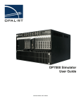
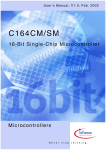
ML605 Board Components
1
2
4
3
8
5
6
9
10
11
7
31
12
30
13
14
29
15
28
27
16
26
17
18
25
23
21
24
19
22
20
Figure 3:ML605 Opal-RT interface board connectors
#
#
Name
Description
1
SFP connector and cage
17
J35
System monitor interface connector
2
DDR3 SODIMM
18
J3
PMBus controller
3
FMC-LPC connector
19
SW5-9
User pushbuttons
4
Name Description
J55-58 GPIO SMA connectors
5
16 character, 2 line LCD display
20
FMC-HPC connector
21
22
6
S2
Mode Switch 6-pole DIP switch
7
S1
System ACE CF image select 4-pole DIP switch 23
J27-29
GTX Rx/Tx ports
PCIe Gen1 (8-lane), Gen2 (4-lane)
Card edge connector, 8-lane
8
USB-A Host, USB Mini-B peripheral connectors 24
9
12V power input connector 6-pin Molex mini-
25
Linear BPI flash
128 Mb Platform flash XL
DVI
Video, DVI connector
fit connector
10
J25
12V power input connector 4-pin ATX disk type
Ethernet (10/100/1000) with SGMII
26
connector
J20
USB-A Host, USB Mini-B peripheral connectors 27
System ACE CF controller, CF connector
28
SW4
Power On/Off
29
14
SW3
FPGA_PROG_B
15
SW10
CPU RST
11
12
13
16
J22
JTAG cable connector (USB mini-B)
J21
USB Mini-B, USB-to-UART bridge
30
GPI0
User DIP switch (8 pole)
31
GPIO
User LEDs (8, green)
MGT REFCLK SMA connectors
PMBus controller
RTXSG User Guide
11
Virtex-6 Specifications
Hardware description and setup
4.2
Virtex-6 Specifications
Part Number XCV6VLX240T
TYPE
Logic
Memory
DATA
37,680
Logic cells
241,152
CLB Flip-flops
301,440
Maximum distributed RAM (Kbits)
3,650
Block RAM/FIFO w/ECC (36Kbits each)
416
Total block RAM (Kbits)
14,976
Clock
Mixed mode clock managers (MMCM)
12
I/O
Maximum single-ended I/O
720
Maximum differential I/O pairs
360
DSP48E1 slices
768
Embedded hard IP
4.3
DESCRIPTION
Slices
PCI Express interface blocks
2
10/100/1000 Ethernet MAC blocks
4
GTX low-power tranceivers
24
OP5600
The OP5600 is a complete simulation system capable of operating with Virtex-6 FPGA platforms. It is designed to
be used either as a desktop (or shelf top) or as a more traditional rack mount. It contains a powerful Target
Computer and a flexible, high-speed Front End Processor and a signal conditioning stage. The new design makes
it easier to use with standard connectors (DB37, RJ45 and mini-BNC) without the need for input/output adaptors
and allows quick connections for monitoring.
4.3.1 Opal-RT Interface Boards
The Opal-RT interface board is a level shifter device coupling the ML605 to the OP5600 carrier board. The ML605
I/O banks are based on a 2.5 V voltage level, while the Opal-RT OP5600 carrier and I/O modules are based on a
3.3 V voltage level. The Opal-RT interface board converts the voltage levels to ensure that the ML605 correctly
drives the Opal-RT I/O modules.
4.3.2 Opal-RT I/O Modules
Mezzanine boards are available in several types:
• OP5353, 32 digital inputs
• OP5354, 32 digital outputs
• OP5330, 16 analog inputs (0.5 MSPS)
• OP5341, 16 analog inputs (2 MSPS)
• OP5340, 16 analog outputs
Refer to the OP5600 HILbox User Manual for more detailed information.
12
RTXSG User Guide
Building models with the RT-XSG toolbox
5
RT-XSG is a Matlab/Simulink toolbox developed by Opal-RT Technologies that enables an convenient
way to create a programming file for the ML605 programmable device. It is used in conjunction with the
System Generator for DSP toolbox from Xilinx.
5.1
Access to the Opal-RT interface board
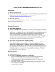
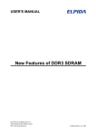
The I/O components available from the Opal-RT interface board can be accessed through a Simulink
User model. Opal-RT Technologies provides an easy to use block set destined to communicate with the
interface board (See Chapter 4 ), and thus with the external conditioning and conversion modules (see
Figure 4). See the help file of each block for more information on how to interface them in the design,
or refer to Appendix A.
Adding an interface to an analog or digital bank is as easy as dragging-and-dropping a block from the
library into the design and feeding it with a signal of appropriate numbering format. For ML605
platform, the user has access to 192 digital I/O lines. Six I/O groups are available, each allowing up to
32 digital I/O lines or 16 analog lines.
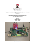
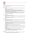
Analog-to-digital and digital-to-analog controllers must be associated into the user design with analog
banks. These controller modules are used to serialize/deserialize and encapsulate the control and data
signals for the 16 16-bit channels associated to each bank . An example of correct association between
the interface block and a DAC controller is presented on Figure 5.
Figure 4:Opal-RT RT-XSG block sets.
RTXSG User Guide
13
Building models with the RT-XSG toolbox
Data type and rate management
Figure 5:Example of an ML605 analog I/O interface block.
5.2
Data type and rate management
Opal-RT RT-XSG library blocks have predefined input/output port fixed-point formats. These formats
cannot be changed by the user as they must match the type expected from external modules ports,
such as the ADC and DAC control signals.
In addition, the clock frequency of the ML605 board is fixed to 100 or 200 MHz. Even if this frequency
can be changed through a programmable chip on the board, user should not attempt to change the
clock frequency. This clock is given by the “USR CLOCK” DIP crystal on the ML605 board. It is
recommended that the user leave the original component in place at all time, as it ensures appropriate
timing for the Opal-RT-supported devices.
Slower processing rates can be achieved by using downsampling and upsampling blocks from the
System Generator for DSP Blockset. Note that he clock distribution is absent from the Simulink RT-XSG
design as it is managed by the Xilinx and Opal-RT toolboxes. However, it is important to keep in mind
the importance of the clock in hardware computing.
Note: Passing through a majority of blocks from the System Generator library induces a delay on the signals, ranging from picoseconds to tens
of nanoseconds. It might be necessary to reduce the sampling rate of certain parts of the computation processes in order for that delay to become
negligible.
5.3
Inserting custom VHDL modules in design
The easiest way to include a VHDL user model into the system is to instantiate it as a “black box” into
the Simulink RT-XSG design. This method may facilitate the interface with Opal-RT conversion module
controllers (ADC and DAC interfaces). Refer to the ‘Black box’ block help from the System Generator for
DSP Blockset for more informations on how to configure a black box.
5.4
Generation of the programming file and target platform recompilation
The ‘Opal-RT FPGA Synthesis Manager’ block includes all the functionalities needed to compile the RTXSG user model and to translate it into a programming file suitable for the reprogrammable device of
14
RTXSG User Guide
Generation of the programming file and target platform recompilation
the ML605 board. It also enables direct configuration of the board using the PCIe connection or a JTAG
Platform cable.
In order to generate the programming file, the following steps must be performed:
• Verify the correctness of the design using the “Update Diagram”
button (Ctrl-D) from the Simulink toolbar and correct the errors, if
any;
• Insert a ‘Opal-RT FPGA Synthesis Manager’ block into your design.
In this block GUI (Figure 6), select the appropriate
reprogrammable platform from the list and click the “Generate
programming file” button. Programming file generation will take
several minutes to complete.
Note: For a programming file to be generated, the user must set the “Rebuild option” parameter to ‘Always’ or ‘Only if changes needed’. This
requirement is included to prevent unwanted compilations, as this operation can take from several minutes to several hours to complete,
depending on the system characteristics.
After the generation of a valid programming file, the user can easily program the target platform by
performing the following steps:
• Connect the ML605 via the ML605 adapter to the PCIe bus of the
target PC.
• Power up the target PC.
• Using RT-LAB, load the real-time Simulink model into the target
PC. RT-LAB will automatically program the ML605 board with the
programming file used by this model (as long as the programming
file is located in the model’s directory).
Note that is is also possible to program the target PC using a JTAG
cable connected from the host PC to the ML605 board (standard
Xilinx tolls must be used for this procedure).
Note: The programming file generation log information is written to the file $Current_Directory/xsg_fpga_model/netlist/xflow/xflow.result.
Generation errors, including resource shortage or routing errors, can be found by parsing this file.
Figure 6:Opal-RT FPGA Synthesis Manager graphical user interface.
RTXSG User Guide
15
Building models with the RT-XSG toolbox
16
Generation of the programming file and target platform recompilation
RTXSG User Guide
Appendices
RTXSG-UG-11-02
RT-XSG Simulink Library Reference Manual
A
1.0.1 Hardware Configuration Block
Library
RT-XSG/ML605
Block
Figure 7:Hardware Configuration Block.
Mask
Figure 8:Hardware Configuration mask.
RT-LAB Installation Guide
18
Hardware Configuration Block
Description
The Hardware Configuration Block is provided to help the user find the appropriate analog or digital, input or
output signal interface on the Wanda 3, Wanda 4 or OP5600 system. The user should specify in ths block the
exact configuration of the Target PC I/O module. Once this block is configured, the user may use an I/O Block to
access any I/O interface. The I/O Block provides the user with all the available signal interface board locations
according to the requested signal type (analog or digital) and direction (input or output). It is recommended that
the user create a library with a preconfigured Hardware Configuration block for every RT-XSG compatible system
available and include this library in the Matlab path and Simulink library Browser for easy configuration and
updates of each design.
Parameters
Active Control Card: Select the type of active board on which the FPGA model is run (e.g. Opal-RT OP5142
Spartan 3 Mezzanine, Xilinx ML605 Development Platform).
Chassis Form Factor: Select the chassis model name. This parameter modifies the Hardware Configuration
Pane and helps locate the available interfaces on the chassis picture. Three choices are available when you select
an Opal-RT OP5142 Spartan 3 Mezzanine as Active Control Card: Wanda 3U, Wanda 4U and OP5600; only
OP5600 chassis is available for Xilinx ML605 Development Platform.
For Wanda3U and Wanda4U, the Hardware Configuration pane suggest the following location:
Slot #1-4 Carrier Type: Select the type of 4U carrier located in the slot 1 to 4. It is recommended to indicate
the carrier type of all non-empty slots. An empty slot is indicated by the <empty> choice and will not be available
to OP5142 I/O blocks.
Slot #1-4 Section A I/O Module: For Type B carriers, a signal conditioning module can be placed on the carrier
board. This parameter is provided to specify the appropriate mezzanine module for such boards (Section A).
Slot #1-4 Section B I/O Module: For Type B carriers, a signal conditioning module can be placed on the carrier
board. This parameter is provided to specify the appropriate mezzanine module for such boards (Section B).
For the OP5600 chassis, the Hardware Configuration pane uses the following points to set the location:
Carrier Type: Select the type of FlatIO carrier type.
Section 1A I/O Module: This parameter is provided to specify the mezzanine module located on this subsection
of the OP5600 chassis.
Section 1B I/O Module: This parameter is provided to specify the mezzanine module located on this subsection
of the OP5600 chassis.
Section 2A I/O Module: This parameter is provided to specify the mezzanine module located on this subsection
of the OP5600 chassis.
Section 2B I/O Module: This parameter is provided to specify the mezzanine module located on this subsection
of the OP5600 chassis.
Section 3A I/O Module: This parameter is provided to specify the mezzanine module located on this subsection
of the OP5600 chassis.This location is unavailable when the Active Control Card selected is Xilinx ML605
Development Platform.
Section 3B I/O Module: This parameter is provided to specify the mezzanine module located on this subsection
of the OP5600 chassis. This location is unavailable when the Active Control Card selected is Xilinx ML605
Development Platform.
Section 4A I/O Module: This parameter is provided to specify the mezzanine module located on this subsection
of the OP5600 chassis.
Section 4B I/O Module: This parameter is provided to specify the mezzanine module located on this subsection
of the OP5600 chassis.
19
RTXSG User Guide
Hardware Configuration Block
Inputs
This block has no input.
Outputs
This block has no output.
Characteristics and Limitations
This block has no special characteristics.
Direct Feedthrough
RTXSG User Guide
NO
Discrete sample time
NO
XHP support
N/A
Work offline
YES
20
Communication Configuration Block
1.0.2 Communication Configuration Block
Library
RT-XSG/ML605
Block
Figure 9:Communication Configuration Block.
Mask
Figure 10:Communication Configuration mask.
21
RTXSG User Guide
Communication Configuration Block
Description
An RT-XSG model can be accessed with application-specific RT-LAB blocks from the Opal-RT I/O library. These
blocks perform all the required data scaling and packaging to control the different analog and digital interface
blocks in the RT-XSG model. The CONF file is a text-based file giving the I/O type, count and location related to
each DataIn and DataOut port accessed by the RT-LAB blocks. This block describes this interface and generates
automatically the CONF file associated with it.
Parameters
DataIn/Out port #: This non editable Column relates all available ports available to the designer for the DataIn
direction (for signals sent from RT-LAB, on the first tab in the interface) or the DataOut direction (for signals sent
to RT-LAB, on the second tab in the interface).
Signal Type: This parameter is used by the developer to set the signal type associated to this port. This
information is used by RT-LAB to determine what features are implemented on the FPGA. Location: These
parameters set the I/O hardware location in the chassis associated to the group of channels controlled by this
port
Inputs
This block has no input.
Outputs
This block has no output.
Characteristics and Limitations
See the RT-XSG User Guide for more information. When the block is opened, the associated .conf file is loaded,
whose location is the only parameter of the block stored in Simulink. When the block is opened, the following
priority is applied to find the correct associated .conf file:
1. The .CONF file with the same relative path to the model as the last time the .CONF file was updated;
2. The .CONF file with the same absolute path as the last time the .CONF file was updated;
3. The .CONF file with the same relative path to the RTXSG_ROOT environment variable as the last time the
.CONF file was updated; Beware when updating this file not to overwrite library .CONF files.
It is recommended to use a copy of the .CONF file located in the model folder.
RTXSG User Guide
Direct Feedthrough
N/A
Discrete sample time
N/A
XHP support
N/A
Work offline
YES
22
OP5142/ML605 I/O Block
1.0.3 OP5142/ML605 I/O Block
Library
RT-XSG/ML605
Block
Figure 11:OP5142/ML605 I/O block.
Mask
Figure 12:OP5142/ML605 I/O block mask.
Description
This block gives access to all I/O modules controlled by the following active cards: the OP5142 board and the
ML605 development board. It uses the OP5142/ML605 Hardware Configuration block to determine all the
interface modules available according to the requested signal type (analog or digital) and direction (input or
output). Implementation of the external connections is also available to enable offline simulation of the complete
system, including external hardware setup. Note that the block input and output ports depend upon the selected
interface board.
23
RTXSG User Guide
OP5142/ML605 I/O Block
Parameters
Type: Type of signal to be interfaced (either analog or digital).
Direction: Direction of signal to be interfaced (either input or output).
Interface: This parameter drop-down menu lists all available interfaces available according to the selected
“Type” and “Direction” parameters and the configuration of the ‘Hardware Config’ block. The user chooses the
appropriate interface to manage the specific signal.
Characteristics: This parameter is not editable. It shows the interface board characteristics for an easy
identification of the board that corresponds to the selected interface location.
Multiplex input/output signals: This checkbox can be used to concatenate multiple input or output signals on
the same Simulink net. This may help the user to build cleaner schematics. The behavior of this feature depends
upon the type of signal interfaced:
• For digital signals, if this option is selected, the interface signal must be a multiple-bit
fixed point format (e.g.: UFix16_0 may be used for a 16- bit multiplexed digital signal);
• For analog signals, if this option is selected, channels are multiplexed two by two, with
a “valid” bit added. For example, the UFix33_0 format may be used for two analog
output channels, the 16 LSBs being the first channel (in a format equivalent to the
UFix16_11 numeric format), the next 16 bits being the second channel (also in a
format equivalent to the UFix16_11 numeric format), and the MSB being the “Valid” bit.
This format is useful for an easy connection to a DataIN or DataOUT block.
Note that for inputs, multiplexed signals are always in an unsigned fixed-point format with the binary point at
position 0 (i.e. a positive integer format). Also, note that the external digital signals provided for offline
simulation correspond to the multiple-bit fixed-point number interfaced by this block, and that the external
analog signals for offline simulations are available in a channel-by-channel basis only.
Number of channels: This parameter is used to select the number of channels to appear on the block icon. This
option is not available when the “Multiplex input/output signal” option is selected. In this case, the channel
number is set to the maximal value allowed by the selected interface board
Show external signal port(s): This checkbox is used to add input or output ports to the block that represent
the external world, from the active control card point of view. These ports can be used to connect the signals to a
model of the external device connected to the signal conditioning modules. This feature can be very useful for
offline simulation of the FPGA model.
Inputs
The block inputs strongly depend upon the parameters chosen in the block mask, and particularly upon the
interface board used to condition the signals:
Analog input interface:
Convert: Convert input signal. Connect this input to the ModelSync “From” for synchronization with an external
master device or provide a asynchronous sync source. If an asynchronous source is used, it must generate a 10ns pulse. The maximum period between two pulses is 2µs (maximum conversion speed of a channel).
Ch{0-15}_external: These signals correspond to the external-world inputs of the analog-to-digital conversion
module. They are used only for offline simulation, and appear only if the “Show external signal port(s)” option is
selected in the block mask. They can be in a floating-point format.
Analog output interface: Convert: Convert input signal. Connect this input to the ModelSync “From” for
synchronization with an external master device or provide a asynchronous sync source. If an asynchronous
source is used, it must generate a 10-ns pulse. The maximum period between two pulses is 1µs (maximum
conversion speed of a channel). To have a synchronization of all the channels at the output of the adigital-toanalog conversion card, all data samples should be presented in sync with the Convert signal.
RTXSG User Guide
24
OP5142/ML605 I/O Block
Ch{0-15}: These ports are the output signals to be sent to the digital-to-analog conversion module (if the
“Multiplex input/output signals” option is not selected). These signals represent the voltage of the module
outputs. Note that these inputs are converted automatically to a Fix16_11 numerical format. Signals outside the
[-16, 15.9995] dynamic range will be wrapped in to a number in the range. Signals with a resolution higher than
0.0005V will lose precision.
Ch{1-15}_Ch{0-14}: These ports are the multiplexed output signals to be sent to the digital-to-analog
conversion module (if the “Multiplex input/output signals” option is selected). These signals represent the voltage
of the module outputs and must be in the UFix33_0 format. The 16 LSBs correspond to the first channel (in a
format equivalent to the Fix16_11 numerical format), the next 16 bits to the second channel (also in a format
equivalent to the Fix16_11 numerical format), and the MSB to a “Valid” bit (this bit is unused for analog output
interfaces).
Digital input conditioning interface:
Ch{0-15}_external: These signals correspond to the external-world inputs of the digital conditioning module (if
the “Multiplex input/output signals” option is not selected). They are used only for offline simulation, and appear
only if the “Show external signal port(s)” option is selected in the block mask. They can be in a floating-point
format.
DInput_external: This signal corresponds to the external-world inputs of the digital conditioning module (if the
“Multiplex input/output signals” option is selected). It is used only for offline simulation, and appears only if the
“Show external signal port(s)” option is selected in the block mask. It can be in a floating-point format.
Digital output conditioning interface: Ch{0-15}: These ports are the output signals to be sent to the digital
conditioning module (if the “Multiplex input/output signals” option is not selected). These signals must be 1-bit
wide.
DOutput: This port corresponds to the output signals to be sent to the digital conditioning module (if the
“Multiplex input/output signals” option is selected). It is a concatenation of the digital output channels. Missing
bits are padded by zeros, if the signal connected to this port have fewer bits than the interface module capacity.
Digital passthrough interface:
Direction: This signal corresponds to the direction of the digital passthough lines. Its width must be equal to the
passthrough interface module capacity (missing bits are padded with zeros). Zeros correspond to an outbound
direction while ones correspond to an inbound direction.
DOutput: This port corresponds to the output signals to be sent to the digital conditioning module. It is a
concatenation of the digital output channels. Missing bits are padded by zeros, if the signal connected to this port
have fewer bits than the interface module capacity, and lines that correspond to inbound signals (as indicated by
the signal connected to the “Direction” port) are unused.
DInput_external: This signal corresponds to the external-world inputs of the digital conditioning module (if the
“Multiplex input/output signals” option is selected). It is used only for offline simulation, and appears only if the
“Show external signal port(s)” option is selected in the block mask. It can be in a floating-point format.
25
RTXSG User Guide
OP5142/ML605 I/O Block
Outputs
The block outputs strongly depend upon the parameters chosen in the block mask, and particularly upon the
interface board used to conditionate the signals:
Analog input interface:
Ch{0-15}: These ports are the input signals received from the analog-to-digital conversion module (if the
“Multiplex input/output signals” option is not selected). These signals represent the voltage of the module inputs.
Note that these outputs are in the Fix16_11 numerical format, giving them a dynamic range of [-16, 15.9995]
and a resolution of 0.0005V.
Ch{1-15}_Ch{0-14}: These ports are the multiplexed input signals received from the analog-to-digital
conversion module (if the “Multiplex input/output signals” option is selected). These signals represent the voltage
of the module inputs and are in the UFix33_0 format. The 16 LSBs correspond to the first channel (in a format
equivalent to the Fix16_11 numeric format), the next 16 bits to the second channel (also in a format equivalent
to the Fix16_11 numeric format), and the MSB to a “Valid” bit (active when the 32 LSBs are updated).
Analog output interface:
Ch{0-15}_external: These signals correspond to the external-world outputs of the digital-to-analog conversion
module. They are used only for offline simulation, and appear only if the “Show external signal port(s)” option is
selected in the block mask. They are in the “double” floating-point format.
Digital input conditioning interface:
Ch{0-15}: These ports are the input signals received from the digital conditioning module (if the “Multiplex
input/output signals” option is not selected). They are 1-bit wide unsigned signals.
DInput: This port corresponds to the input signals received from the digital conditioning module (if the
“Multiplex input/output signals” option is selected). It is is a concatenation of the digital input channels. The
signal width is equal to the interface module capacity.
Digital output conditioning interface:
Ch{0-15}_external: These signals correspond to the external-world inputs of the digital conditioning module (if
the “Multiplex input/output signals” option is not selected). They are used only for offline simulation, and appear
only if the “Show external signal port(s)” option is selected in the block mask. They are in the “double” floatingpoint format.
DOutput_external: This signal corresponds to the external-world outputs of the digital conditioning module (if
the “Multiplex input/output signals” option is selected). It is used only for offline simulation, and appears only if
the “Show external signal port(s)” option is selected in the block mask. It is in the “double” floating-point format.
Digital passthrough interface:
DInput: This port corresponds to the input signals received from the digital conditioning module. It is a
concatenation of the digital input channels. Its width corresponds to the interface module capacity, and lines that
correspond to outbound bound signals (as indicated by the signal connected to the “Direction” port) are equal to
the correspoding line of the signal connected to the “DInput” port. DOutput_external: This signal corresponds
to the external-world outputs of the digital conditioning module. It is used only for offline simulation, and appears
only if the “Show external signal port(s)” option is selected in the block mask. It is in the “double” floating-point
format.
Characteristics and Limitations
This block has no special characteristics.
Direct Feedthrough
RTXSG User Guide
NO
Discrete sample time
NO
XHP support
N/A
Work offline
YES
26
DataIN
1.0.4 DataIN
Library
RT-XSG/ML605
Block
Figure 13::DataIN block.
Mask
Figure 14:DataIN mask.
Description
This block represents the input link to the FPGA through the PCIe bus. Data may be coming from the target PC
CPU model or from a previous FPGA in a multiple chip design. Up to thirty-two input ports are provided to the
user for data samples and control signal transfers.
One of the functions of this block is to perform data conversion from uint32 to the System Generator UFix33_0
data format. It is up to the user to extract the desired data out of the 32 least significant bits and to reinterpret
these bits to the desired format (signed or unsigned with or without binary point).
This block is linked to the inputs of the RT-LAB OpCtrl Reconfigurable IO block found in the RT-LAB CPU model:
port #1 of the OpCtrlReconfigurableIO corresponds to DataIN1, port #2 to DataIN2, etc.
Parameters
Transfer Mode: The buffering type allows a user to choose whether the incoming data is sent in the
synchronous mode, where only one data sample can be transfered per calculation step, or in the asynchronous
mode, where up to 254 samples can be transfered per calculation step. For example, a value of
010000000000101 in this field sets input ports 1 and 3 and 15 (MSB to LSB port representation) to the
asynchronous mode.
27
RTXSG User Guide
DataOUT
Number of ports: This parameter allows the user to use multiple data ports to communicate information to
parallel processors. When the number of ports is changed, the length of the “Transfer Mode” string is updated
accordingly.
Inputs
Data_IN: This is a vector of uint32 type signals (with a length equal to the number of ports). Each of these
signals represents an input port on the OpCtrlReconfigurableIO block of the RT-LAB CPU model. It is used for
offline simulation only.
Outputs
DataIN{1,...,32}: Each of these ports is in the UFix33_0 format where the first 32 bits represent the data and
bit 33 (the most significant bit) is the valid signal indicating when the information is updated. When in
synchronous mode (default) the valid bit is in sync with the ModelSync train pulses (active high for 10 ns). In
asynchronous or in burst mode, this bit is active on each arrival of the data.
Characteristics and Limitations
This block has no special characteristics.
Direct Feedthrough
NO
Discrete sample time
NO
XHP support
N/A
Work offline
YES
1.0.5 DataOUT
Library
RT-XSG/ML605
Block
Figure 15:DataOUT block
Mask
Figure 16:DataOUT mask.
RTXSG User Guide
28
DataOUT
Description
This block represents the output data link from the FPGA through the PCIe bus. Data may be going to the target
PC (RT-LAB CPU model) or to another FPGA board in a multiple chip design (only RT-LAB CPU models are
supported in this version). A maximum of thirty-two output ports are provided to the user for data samples and
control signal transfers. One of the functions of this block is to do data conversion from the Xilinx System
Generator UFix or Fix format to the uint32 data format.
This block is linked to the output ports of the OpCtrl ReconfigurableIO block found in the RT-LAB CPU model: port
#1 of the OpCtrlReconfigurableIO block corresponds to DataOUT1, port #2 to DataOUT2, etc. Two modes are
available. When in FIFO mode, all data sent to the DataOUT block between two data acquisition synchronization
signal pulses is transmitted. When in Register mode, the last data befor the synchronization signal pulse is
transmitted. Note: Data arriving synchronouly with the synchronization signal belongs to the ending timestep.
Parameters
Number of ports: This parameter allows the user to use multiple data ports to communicate information with
parallel processors. When the number of ports is changed, the length of the “Transfer Mode” string is updated
accordingly.
Buffering type: The buffering type allows a user to choose whether to buffer the information in a single register
where only one data sample can be transfered per calculation step or in a FIFO buffer-based mode where up to
254 samples can be transfered per calculation step. For example, a value of 010000000000101 in this field sets a
FIFO on DataOUT ports 1 and 3 and 15 (MSB to LSB port representation). In FIFO mode, the number of samples
stored is determined by the number of 10 ns pulses (one FPGA clock cycle) on bit 32 (MSB) of the port in FIFO
mode per calculation step.
Provide external data synchronization signal: This parameter may be used to postpone the data acquisition
by the DataOUT communication module. When in normal mode, the data acquisiti on occurs synchronously with
the synchronization signal. By using the postponed mode, it is possible to delay the acquisition of the data from 0
to 15 clock cycles. This feature may be used to complete pipelined computation on data that belongs to the
ending timestep, or to transfer serially multi-channel data acquired synchronously with the synchronization
signal. A ‘1’ for a channel adds an input port for the developer to provide the external synchronization signal. A ‘0’
forces the use of the ModelSync signal to be used as the data acquisition synchronization signal (default).
Inputs
Data_OUT{1,...,32}: Each of these ports is in the UFix33_0 format where the first 32 bits represent the data
and bit 33 (the most significant bit) is the valid signal indicating when the data is ready. Bit 33 can be seen as a
write signal to the buffer, whether it be a register or a FIFO, in the DataOUT block. Each of those buffers is
emptied and transfered to the CPU model at the beginning of each calculation step.
DataSync{1,...,32}: If requested from the block parameter panel, each of these ports enables the developer to
provide an external, delayed data acquisition synchronization signal for each output data channel. It is
recommended to connect this input to a delayed version of the ModelSync signal (accessed through a “From”
built-in Simulink block). The external synchronization pulse must occur within a delay of 0 to 15 clock cycles after
the master ModelSync pulse. Pulses observed outside this time range will be taken into account for data
transmission in the next computation step.
Outputs
DataOUT: This is a vector of signals in the uint32 format (with a length equal to the number of ports). Each one
of these signals represents an output port on the OpCtrlReconfigurableIO block in the RT-LAB CPU model. This
port is used for offline simulation only.
Characteristics and Limitations
29
RTXSG User Guide
DataOUT
This block has no special characteristics.
Direct Feedthrough
NO
Discrete sample time
NO
XHP support
N/A
Work offline
RTXSG User Guide
YES (No for ports set in
FIFO mode)
30
LoadIn
1.0.6 LoadIn
1.0.6.0.1
Library
RT-XSG/ML605
1.0.6.0.2
Block
Figure 17:ML605 Cfg_IN (LoadIn) block
1.0.6.0.3
Mask
Figure 18:ML605 Analog I/Os mask.
1.0.6.0.4
Description
This block represents the input link of the FPGA through the SignalWire bus. Data may be
coming from the PC target of from a previous FPGA in a multiple chip design. Sixteen input
ports are provided to the user for data samples and control signal transfers. One of the
functions of this block is to perform data conversion from uint32 to the System Generator
UFix33_0 data format. It is up to the user to extract the desired data out of the 32 least
significant bits and to reinterpret these bits to the desired format (signed or unsigned with
or without binary point).
This block is linked to the inputs of the OpCtrl Reconfigurable IO block found in the RT-LAB
CPU model: port #1 of the OpCtrlReconfigurableIO corresponds to Cfg_IN1, port #2 to
Cfg_IN2, etc.
31
RTXSG User Guide
Parameters
1.0.6.0.5
Parameters
The buffering type allows a user to choose whether to synchronize incoming data, where
only one data sample can be transfered per calculation step, or to admit asynchronous mode
where up to 254 samples can be transfered per calculation step.
For example, a value of 010000000000101 in this field sets input ports 1 and 3 and 15 (MSB
to LSB port representation) to asynchronous mode
1.0.6.0.6
Inputs
Cfg_IN: This is a vector of 16 uint32 type signals. Each of these signals represents an input
port on the OpCtrlReconfigurableIO block of the RT-LAB CPU model.
1.0.6.0.7
Outputs
Cfg_IN{1,...,16}: Each of those ports is of UFix33_0 format where the first 32 bits
represent the data and bit 33 (most significant bit) is the valid signal indicating when the
information is updated. When in synchronous mode (default) the valid bit is in sync with the
MSync or model calculation step (active high for 10 ns). In asynchronous or in burst mode,
this bit is active on arrival of the data
1.0.6.0.8
Characteristics and Limitations
This block has no special characteristics.
RTXSG User Guide
Direct Feedthrough
NO
Discrete sample time
NO
XHP support
N/A
Work offline
YES
32
LoadOut
1.0.7 LoadOut
1.0.7.0.1
Library
RT-XSG/ML605
1.0.7.0.2
Block
Figure 19:ML605 Digital I/Os block
1.0.7.0.3
Mask
Figure 20:ML605 Digital I/Os mask.
1.0.7.0.4
Description
This block represents the output data link from the FPGA through the PCIe bus. Data may be
going to the target PC (RT-LAB CPU model) or to another FPGA board in a multiple chip
design (only RT-LAB CPU models are supported in this version). A maximum of thirty-two
output ports are provided to the user for data samples and control signal transfers. One of
the functions of this block is to do data conversion from the Xilinx System Generator UFix or
Fix format to the uint32 data format.
This block is linked to the output ports of the OpCtrl ReconfigurableIO block found in the RTLAB CPU model: port #1 of the OpCtrlReconfigurableIO block corresponds to Cfg_OUT1, port
#2 to Cfg_OUT2, etc.
Two modes are available. When in FIFO mode, all data sent to the DataOUT block between
two data acquisition synchronization signal pulses is transmitted. When in Register mode,
the last data befor the synchronization signal pulse is transmitted. Note: Data arriving
synchronouly with the synchronization signal belongs to the ending timestep.
33
RTXSG User Guide
Parameters
1.0.7.0.5
Parameters
Number of ports: This parameter allows the user to use multiple data ports to
communicate information with parallel processors. When the number of ports is changed,
the length of the “Transfer Mode” string is updated accordingly.
Buffering type: The buffering type allows a user to choose whether to buffer the
information in a single register where only one data sample can be transfered per calculation
step or in a FIFO buffer-based mode where up to 254 samples can be transfered per
calculation step. For example, a value of 010000000000101 in this field sets a FIFO on
DataOUT ports 1 and 3 and 15 (MSB to LSB port representation). In FIFO mode, the number
of samples stored is determined by the number of 10 ns pulses (one FPGA clock cycle) on bit
32 (MSB) of the port in FIFO mode per calculation step.
1.0.7.0.6
Inputs
Cfg_OUT{1,...,32}: Each of these ports is in the UFix33_0 format where the first 32 bits
represent the data and bit 33 (the most significant bit) is the valid signal indicating when the
data is ready. Bit 33 can be seen as a write signal to the buffer, whether it be a register or a
FIFO, in the DataOUT block. Each of those buffers is emptied and transfered to the CPU
model at the beginning of each calculation step.
1.0.7.0.7
Outputs
Cfg_OUT: This is a vector of signals in the uint32 format (with a length equal to the number
of ports). Each one of these signals represents an output port on the OpCtrlReconfigurableIO
block in the RT-LAB CPU model. This port is used for offline simulation only.
1.0.7.0.8
Characteristics and Limitations
This block has no special characteristics.
Direct Feedthrough
N/A
Discrete sample time
N/A
XHP support
Work offline
RTXSG User Guide
N/A
YES (No for ports set in FIFO
mode)
34
DD3R_SRAM_IF
1.0.8 DD3R_SRAM_IF
1.0.8.0.1
Library
RT-XSG/ML605
1.0.8.0.2
Block
Figure 21:ML605 Digital I/Os block
1.0.8.0.3
Mask
Figure 22:ML605 Digital I/Os mask.
35
RTXSG User Guide
Description
1.0.8.0.4
Description
This block is used to control and access the DDR3 SDRAM SODIMM memory module located
one the ML605 board.
The current implementation only supports a single 512 MB DDR3 SDRAM SODIMM with the
following data trasnfer rate: PC3-8500 (DDR3-1066). Because of limitations imposed by the
speed grade of the FPGA, the maximum clock frequency of this memory is set to 400 MHz.
The clock frequency of the User Interface (UI) data and control signals is set to half of the
frequency of the memory clock. Therefore, the clock frequency of the UI is set to 200 MHz
The latency between a READ command and the corresponding data valid signal at the UI is
40 clock cycles (38 for a bank already opened).
This block is based on the User Interface (UI) of the DDR3 memory controller as generated
for a Virtex-6 devices by the Xilinx tool Memory Interface Generator (MIG, v3.5). The
associated DDR3 memory controler was also generated using the MIG tool. Please refer to
the Xilinx document UG406 for more details regarding the the DDR3 SDRAM controler and
its UI.
Reference: Xilinx UG406 - Virtex-6 FPGA Memory Interface Solutions User Guide. The
design of the DDR3_SDRAM_IF block was originally based on version 1.5 of this document.
IMPORTANT INFORMATION regarding the Write Path: As stated in the Xilinx document
UG406 in Chapter 1: DDR2 and DDR3 SDRAM Memory Interface Solution, Section
Interfacing to the Core, sub-section Write Path: "The maximum delay for a single write
between the write data and the associated write command is two clock cycles. When issuing
back-to-back write commands, there is no maximum delay between the write data and the
associated back-to-back write command.". It is important to note that when the "BL8 - 512bit data ports" Implementation Type is selected, the maximum delay for a single write
between the write data and the associated write command is one clock cycles and not two
because the second clock cycle delay is already used inside the
DDR3_SDRAM_IF_BL8_Adaptor subsystem. Also note that this limitation does not apply to
the OTF Implementation Type, regardless of the value of the app_sz input port.
1.0.8.0.5
Parameters
Implementation Type: This parameter sets the withh of the data ports of the User
Interface.
OTF - 256-bit data ports: with this implementation, data can be written of the wdf data
port as late as 2 cycle following the WRITE command.
BL8 - 512-bit data ports: with this implementation, data can be written of the wdf data
port as late as 1 cycle following the WRITE command.
Provide RAM controller reset port: Selecting the Provide RAM controller reset port option
activates an optional reset (rst) pin on the block. When the reset signal is asserted the block
goes back to its initial state.
RTXSG User Guide
36
Inputs
1.0.8.0.6
Inputs
app_addr[ADDR_WIDTH-1:0]: This input indicates the address for the current request.
Implementation Type
Address Bus Width
Data Bus Width
OTF (256-bit data ports)
ADDR_WIDTH = 24
APP_DATA_WIDTH = 256
BL8 (512-bit data ports)
ADDR_WIDTH = 23
APP_DATA_WIDTH = 512
The address space is flat so each individual address is associated with a specific data. The
size of that specific data is equal to the data bus width for to the selected Implementation
Types.
app_rdwr_b: This input selects the command for the current request. In the original design
generated by MIG, this input was a 3-bit wide input port named app_cmd but since there are
only two implemented commands (read & write), the port was changed to a 1-bit port
named app_rdwr_b (1: read command, 0: write command).
app_en: This is the active-High strobe for the app_addr[], app_rdwr_b, app_sz, and
app_hi_pri inputs.
app_hi_pri: This active-High input elevates the priority of the current request.
app_sz (OTF Implementation Type only): For DDR3 SDRAM, app_sz can be changed
dynamically if Implementation Type is set to OTF. For BC4, this bit should be set to 0. For
BL8, this bit should be set to 1.
app_wdf_data[APP_DATA_WIDTH-1:0]: This provides the data for write commands.
Please note that the width of the interface to the controller is always 256 bit. When the BL8
Implementation Type is selected the 512 bits of data are split into two consecutives accesses
of 256 bit each.
app_wdf_end: This active-High input indicates that the current clock cycle is the last cycle
of input data on app_wdf_data[].
app_wdf_mask: This provides the mask for app_wdf_data[].
app_wdf_wren: This is the active-High strobe for app_wdf_data[].
rst (optional): This is the active-High UI reset. When asserted, the entire DDR3 controller
is reset.
37
RTXSG User Guide
Outputs
1.0.8.0.7
Outputs
app_rd_data[APP_DATA_WIDTH-1:0]: This provides the output data from read
commands. Please note that the width of the interface to the controller is always 256 bit.
When the BL8 Implementation Type is selected the 512 bits of data are split into two
consecutives accesses of 256 bits each.
app_rd_data_end: This active-High output indicates that the current clock cycle is the last
cycle of output data on app_rd_data[]. This output is not available for the BL8
Implementation Type. The signal generated by this port is a Boolean.
app_rd_data_valid: This active-High output indicates that app_rd_data[] is valid. The
signal generated by this port is a Boolean.
app_wdf_rdy: This output indicates that the write data FIFO is ready to receive data. Write
data is accepted when app_wdf_rdy = 1’b1 and app_wdf_wren = 1’b1. The signal generated
by this port is a Boolean.
app_rdy: This output indicates that the UI is ready to accept commands. If the signal is
deasserted when app_en is enabled, the current app_cmd and app_addr must be retried
until app_rdy is asserted. The signal generated by this port is a Boolean
1.0.8.0.8
Characteristics and Limitations
This block has no special characteristics.
Limitation: This block can only be used in models using the 200 MHz Clock Frequency
Selection. Please see the OPAL_RT FPGA SynthesisManager block (Library: RT-XSG -> Tools)
for more details
RTXSG User Guide
Direct Feedthrough
NO
Discrete sample time
NO
XHP support
N/A
Work offline
NO
38
Characteristics and Limitations
39
RTXSG User Guide